information for model year 1982
WIS 00-980
Extract from introductory brochure
Engine 616
Positive crankcase ventilation
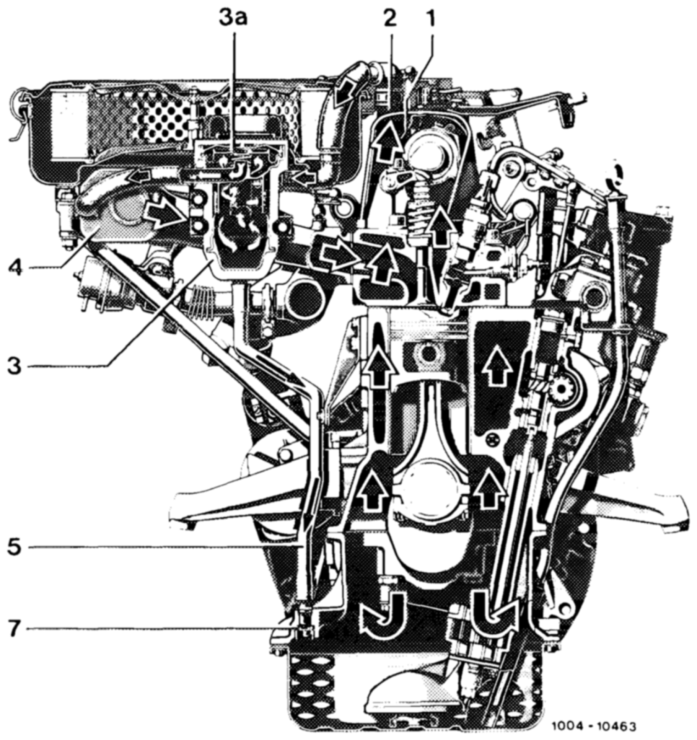
the throttle valve) the diaphragm in the differential The positive crankcase ventilation system is mainpressure valve (3a) is pulled down, restricting the flow tenance free. cross section to the intake manifold. The engine blow-by gases and crankcase vapors flow During this period, only a limited amount of blow-by across the vent insert (1) and connection fitting (2) to the cyclone oil separator (3) which is attached to gases will flow to the intake manifold. the intake manifold. The oil separated in the cyclone oil separator (3) flows through the return line (6) and the check valve (7), From here, they flow through the air intake duct (4) to the intake manifold and with the intake air into installed in the oil pan upper half, back into the oi! pan. The check valve insures that no oil vapors from the combustion chambers. the oil pan are drawn into the intake system due to At avery high intake manifold vacuum (caused by the existing vacuum.
Fig 12
1 Vent insert 4 Intake manifold
2 Connection fitting 6 Return line
3 Cyclone oil separator 7 Check valve 3a Differential pressure valve
Cylinder head cover
Air cleaner
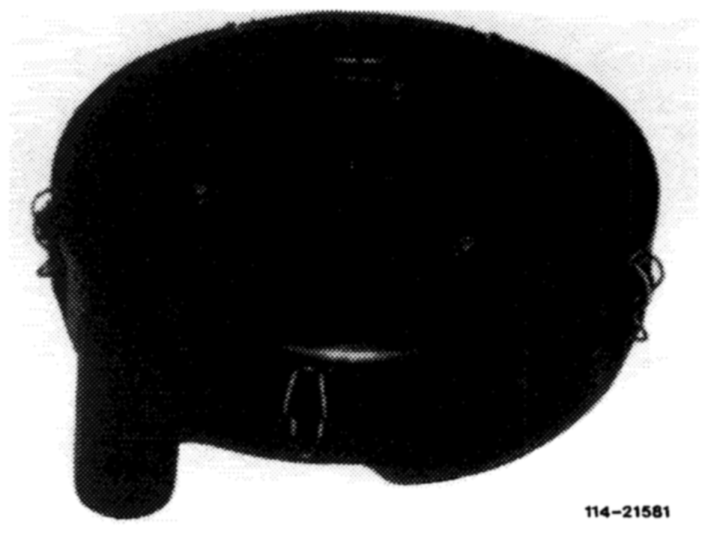
Similar to engine 617.95 (turbodiesel) with EGR, the Air cleaner housings are made of both, aluminium or breather pipe screwed to the inside of the cylinder plastic, and either one may be installed. head cover has been replaced by a vent insert which is riveted into the cylinder head cover and sealed with silicone rubber.
As a result, the oil separating chamber (calm region) included in the engine ventilation system has been increased in volume.
Fig. 13
Exhaust gas recirculation (EGR)
Engine 616 is provided with EGR, which is different In addition, the engine speed and the driving speed in function and operation from that on engines are monitored by an electronic control unit, which 617.912 and 617.95. in turn activates a switchover valve. As a result, EGR is switched off when necessary. EGR is controlled by way of a throttle valve housing attached to the intake manifold, as well as by an EGR valve.
Functional diagram with automatic transmission
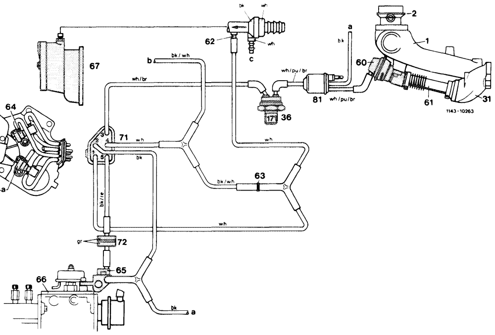
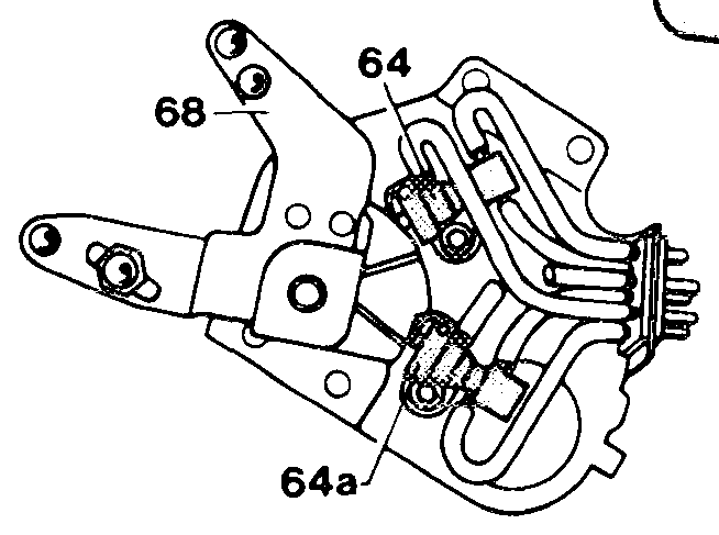
Fig. 14
1 Intake manifold 65 Vacuum control valve Color code
2 Throttle valve housing 66 Injection pump bk = black
31 Exhaust manifold 67 Vacuum pump br = brown
36 Thermo-vacuum valve 17 °C 68 Lever with cam gr = green
60 EGR valve 71 Central plug pu = purple
61 Corrugated tube 72 Surge damper, vacuum re = red
62 Orifice 81 Switchover valve, electric wh = white
63 Orifice
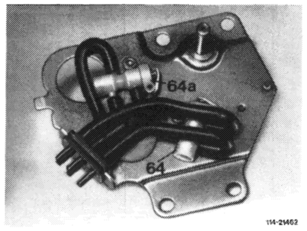
64 Switchover valve, mechanical, EGR Vent to passenger compartment a 64a Switchover valve, mechanical, To automatic transmission b automatic transmission To additional vacuum consumers c
Functional diagram with manual transmission
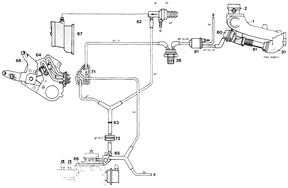
Fig. 15
1 Intake manifold 66 Injection pump Color code
2 Throttle valve housing 67 Vacuum pump bk = black 31. Exhaust manifold 68 Lever with cam br = brown
36 Thermo-vacuum valve 17 °C 71 Central plug gr = green
60 EGR valve 72 Surge damper, vacuum pu = purple
61 Corrugated tube 81 Switchover valve, electric re = red
62 Orifice wh = white
63 Orifice a Vent to passenger compartment
64 Switchover valve, mechanical, EGR c To additional vacuum consumers
65 Vacuum control valve
EGR components Exhaust manifold
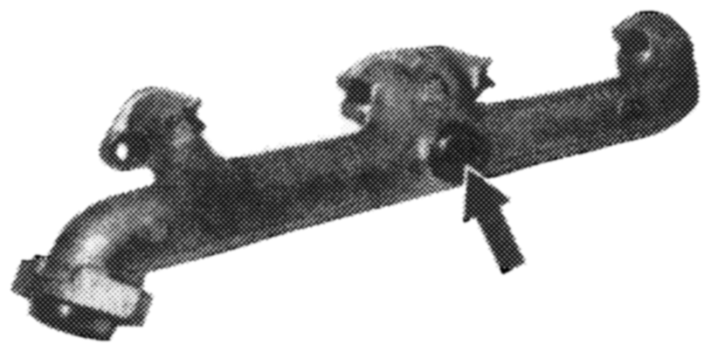
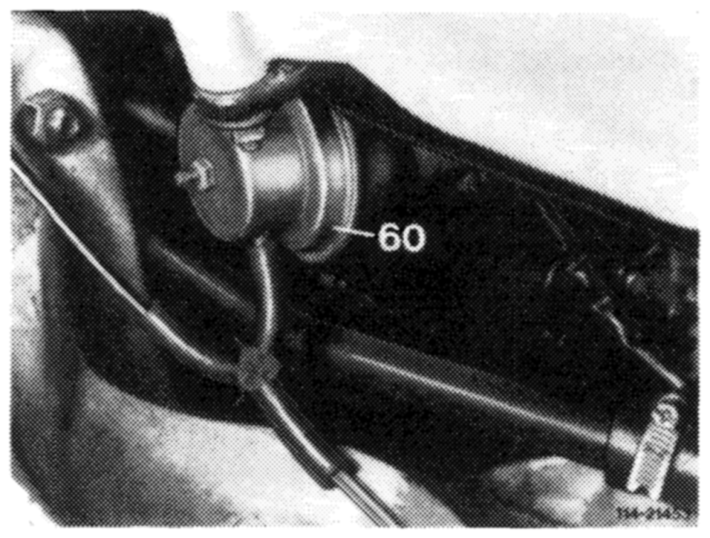
An outlet connection (arrow) is attached to the exhaust The EGR valve, vacuum control valve, thermo-vacuum manifold to provide the exhaust gases for recirculation valve 17 °C and switchover valve, mechanical are identical with those of engine 617 of model year 1981.
Intake manifold
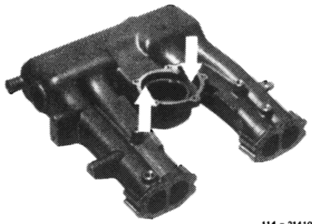
A spiral-shaped channel (arrows) is located around the intake opening of the intake manifold, through which the recirculated exhaust gas is routed and mixed with the intake air. The EGR valve is attached to the intake manifold as on engine 617 in model year 1981 (arrow, Fig. 17).
Fig. 18
Throttle valve housing
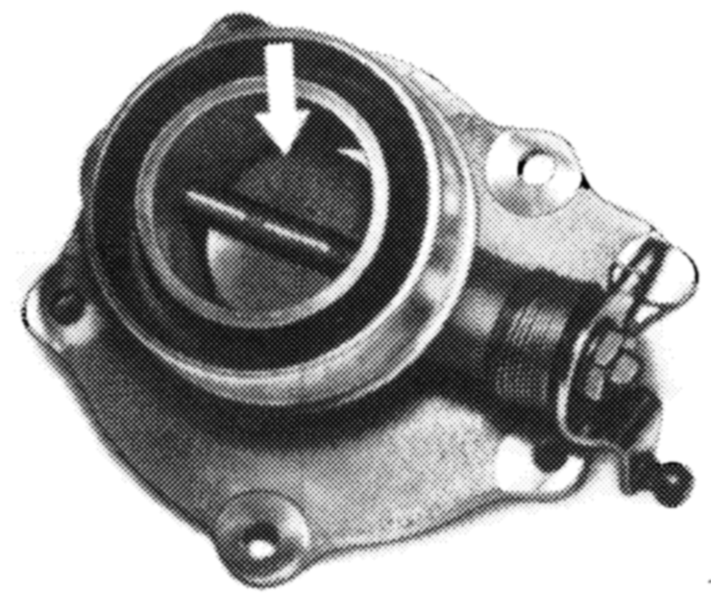
The throttle valve housing is required to increase the amount of EGR in the partial load range.
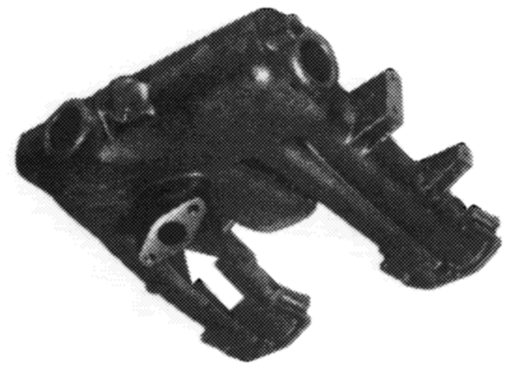
Fig. 16
WABISTE
Fig. 19
Depending on the position of the regulating linkage (load condition of engine) the position of the throttle valve (arrow) and thereby the pressure difference between exhaust manifold and intake manifold are changed.
Fig. 17
High pressure differential = high EGR
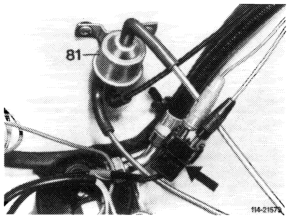
Electric switchover valve
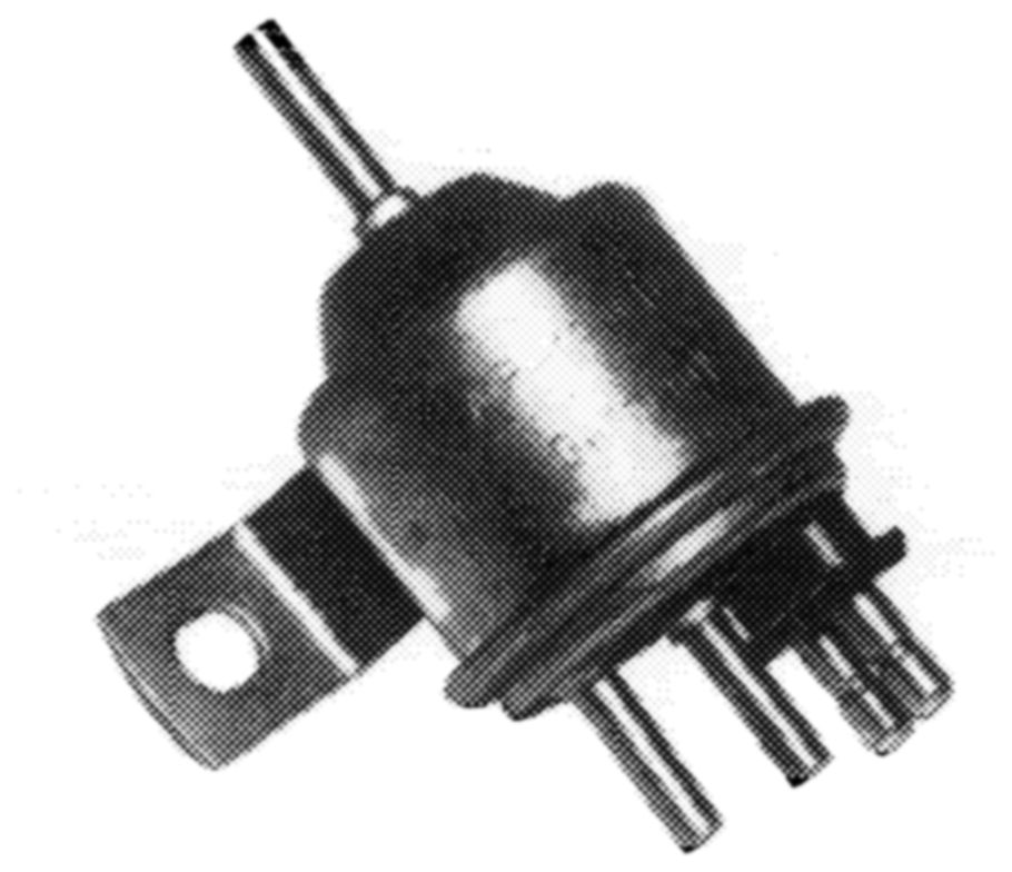
The OD of the throttle valve is designed so that in its The switchover valve controls the vacuum to the EGR closed position an annular cross section remains valve. It opens or closes by way of an electronic open. As a result, the engine will idle smoothly at control unit depending on engine rpm and vehicle high altitudes with the driving position engaged, the speed. air conditioning system switched on and the power steering activated.
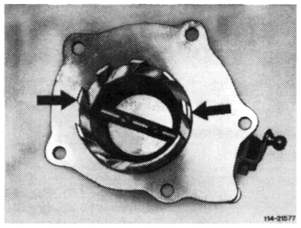
The lower half of the throttle valve housing is provided with guide vanes (arrows). These vanes insure complete mixing of intake air and recirculated exhaust gas, so that each cylinder is provided with the same quantity of exhaust gas.
114 ~ 21401
Fig. 22
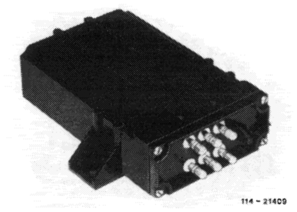
Control unit
The control unit processes input data such as engine rpm from the TDC transmitter and driving speed from the impulse transmitter of the speedometer Fig. 20 (refer to electric wiring diagram).
Corrugated tube
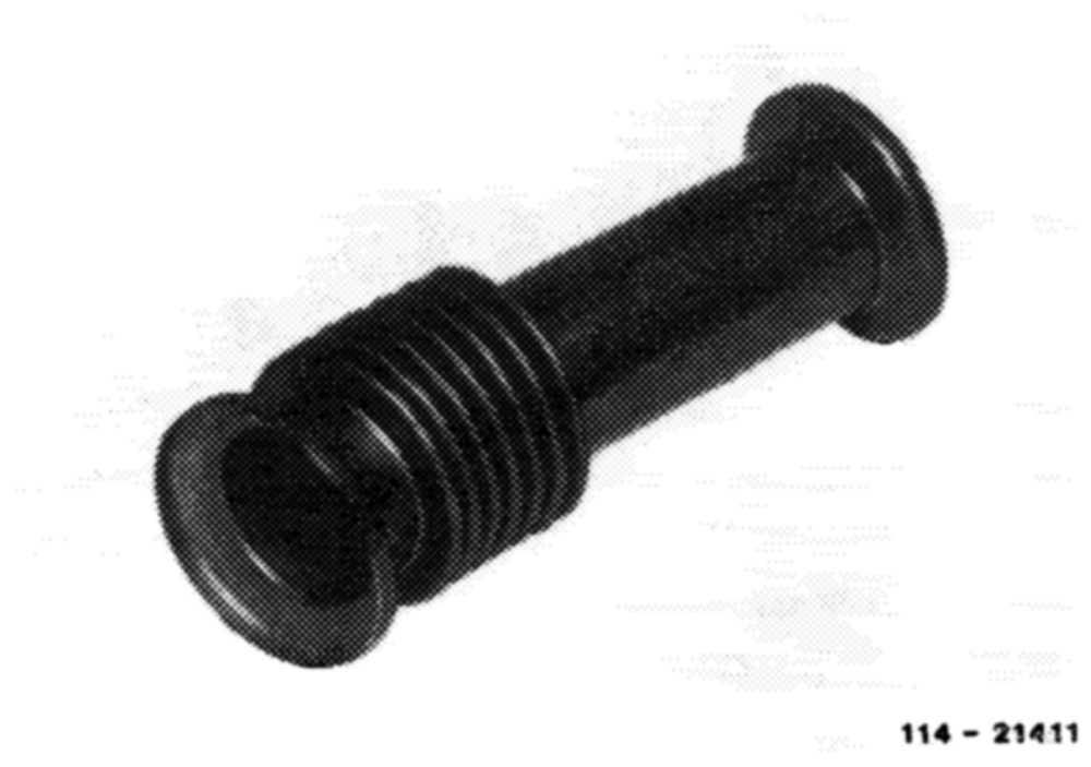
Exhaust gases are returned through a corrugated tube installed between exhaust manifold and EGR valve.
Fig. 23
Fig. 21
Description of Operation
Orifice
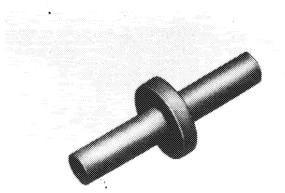
EGR operates under the following conditions To the existing orifices Coolant temperature above 17 °c green 0.7 mm Engine speed above * 198 rpm white 0.8mm (+100 with increasing rom, —130 with decreasing rpm) blue 1.0mm Speed below 73 + 8 km/h red 1.4mm Under partial load yellow 2.0mm, the orifice brown 0.9mm _ has been added. Thermo-vacuum valve {36} opens at a coolant temperature above approx. 17 °C. The vacuum can now reach the electric switchover vaive (81).
Idle speed
The electric switchover valve (81) is not energized and the EGR vaive is externally vented. There is no EGR.
Engine speed above 1300 rpm
Starting at an engine speed of 1300 rpm the impulses from the TDC transmitter are converted into a control signal. The switchover valve (81) is energized and W717058 opens. The vacuum arrives at the EGR valve and opens the valve against its spring force. The EGR valve Fig. 24 Opens a certain amount, depending on engine load
Depressing the accelerator pedal will overcome the
TDC transmitter
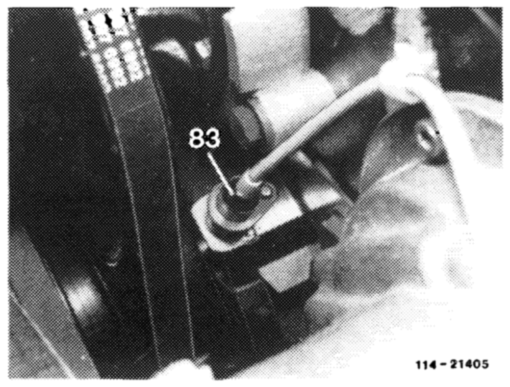
free travel on the drag lever and wil! start to open the throttle valve via a connecting rod. The pressure A TDC transmitter is attached to the front of the differential between the intake and exhaust manifolds cylinder block and transmits the engine rpm to the is progressively reduced. As a result, less exhaust gases control unit for EGR. are drawn into the intake manifold.
The vacuum control valve (65) determines the amount of vacuum at the EGR valve depending on engine load. This amount of vacuum serves as controlling factor for EGR (position of EGR valve) and the shifting of the automatic transmission.
Shortly before full throttle, the lever with cam (68)
switches the mechanical switchover valve (64) to external venting. The vacuum on the EGR valve is completely vented and there is no more EGR.
Speed above approx. 73 + 8 km/h
At a speed above approx. 73 + 8 km/h the impulses transmitted from impulse transmitter on the speedometer are converted into a contro! signal. The current to the electric switchover valve (81) is interrupted. The EGR valve is switched to external venting, there is no more EGR.
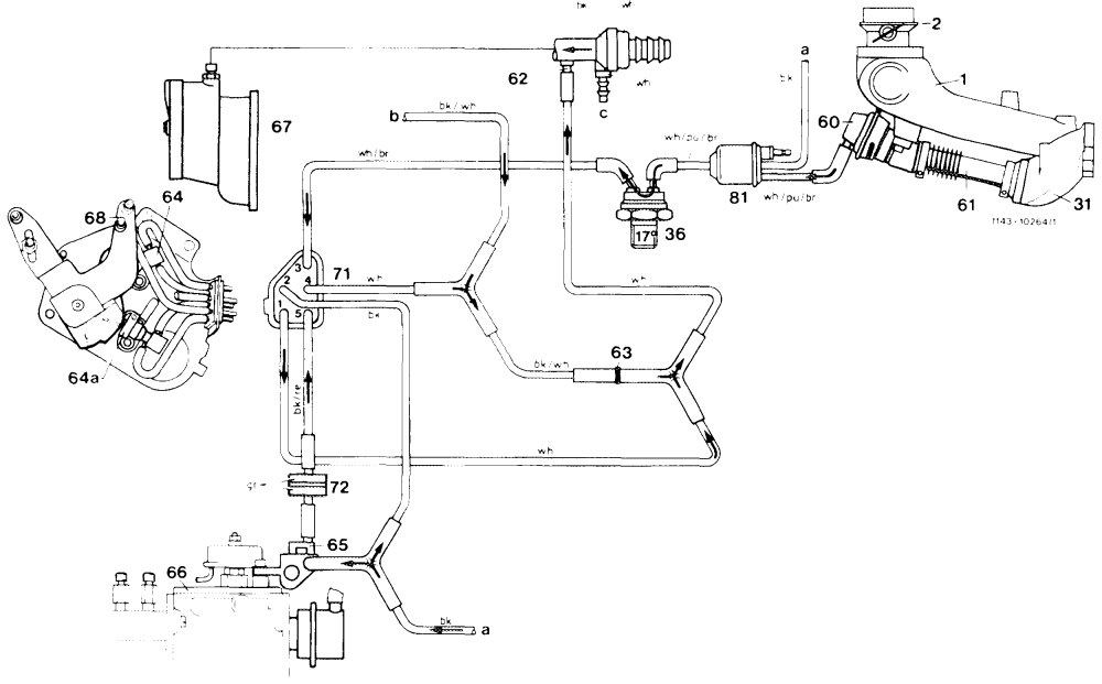
Fig. 26
1 Intake manifold 65 Vacuum control valve Color code
2 Throttle valve housing 66 Injection pump bk = black
31 Exhaust manifold 67 Vacuum pump br = brown
36 Thermo-vacuum valve 17 °C 68 Lever with cam gr = green
60 EGR valve 71 Central plug pu = purple
61 Corrugated tube 72 Surge damper, vacuum re = red
62 Orifice 81 Switchover valve, electric wh = white
63 Orifice
64 Switchover valve, mechanical, EGR a Vent to passenger compartment 64a Switchover valve, mechanical, b To automatic transmission automatic transmission c To additional vacuum consumers
Vacuum flow at an engine speed above 1300 rpm (manual transmission)
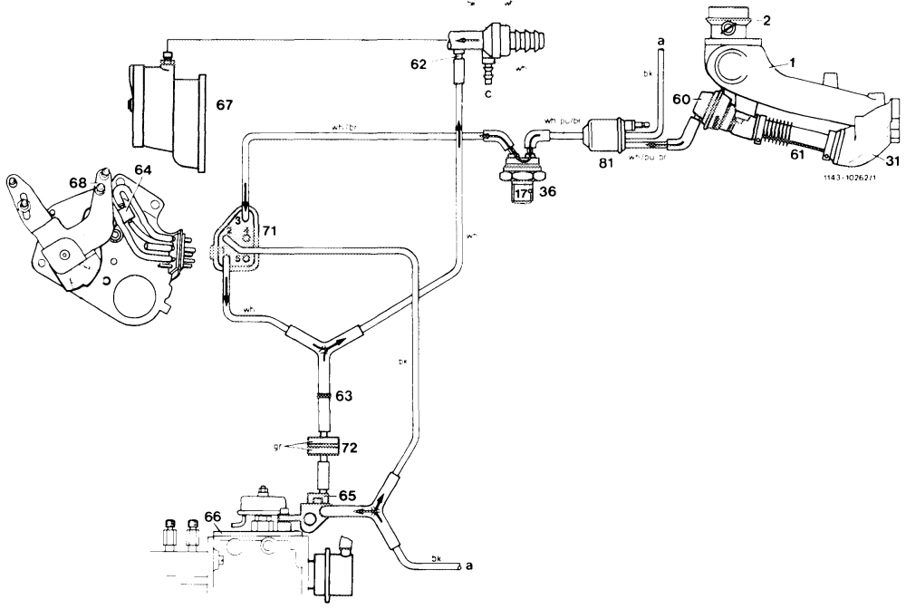
Fig. 27
1 Intake manifold 66 Injection pump Color code
2 Throttle valve housing 67 Vacuum pump bk = black
31 Exhaust manifold 68 Lever with cam br = brown
36 Thermo-vacuum valve 17 °C 71 Central plug gr = green
60 EGR valve 72 Surge damper, vacuum pu = purple
61 Corrugated tube 81 Switchover valve, electric re = red
62 Orifice wh = white
63 Orifice a Vent to passenger compartment
64 Switchover valve, mechanical, EGR c To additional vacuum consumers
65 Vacuum contro! valve
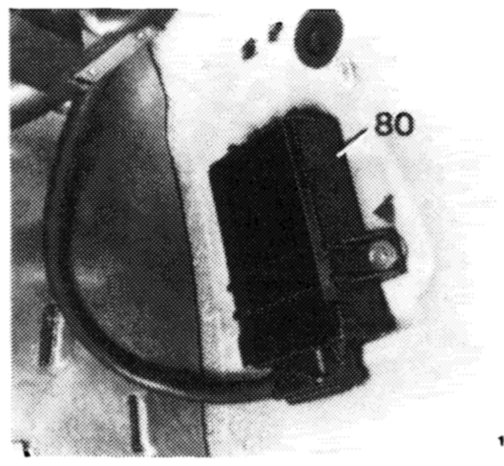
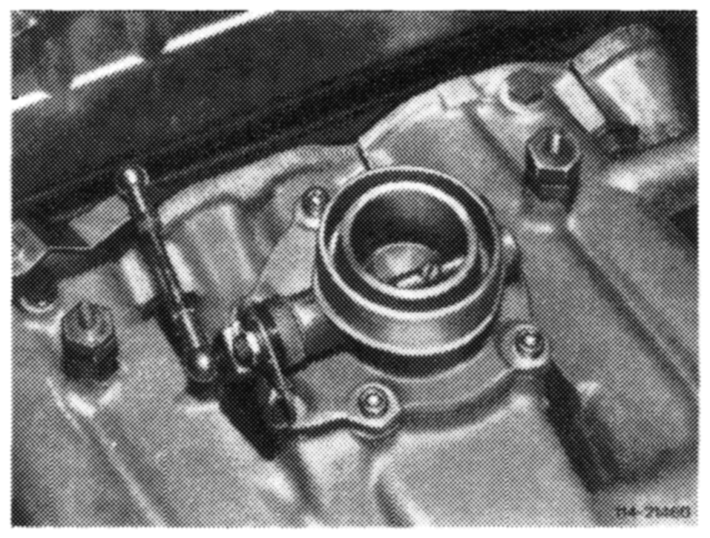
Fig. 28 Fig. 31. Throttle valve housing
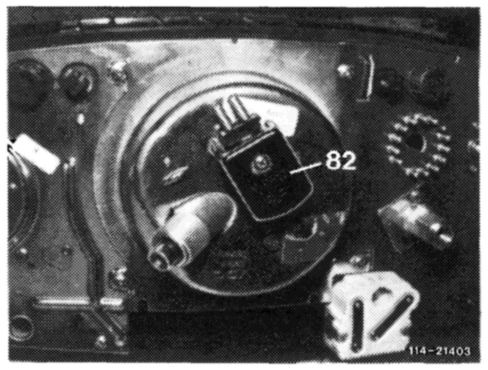
80 Electronic control unit
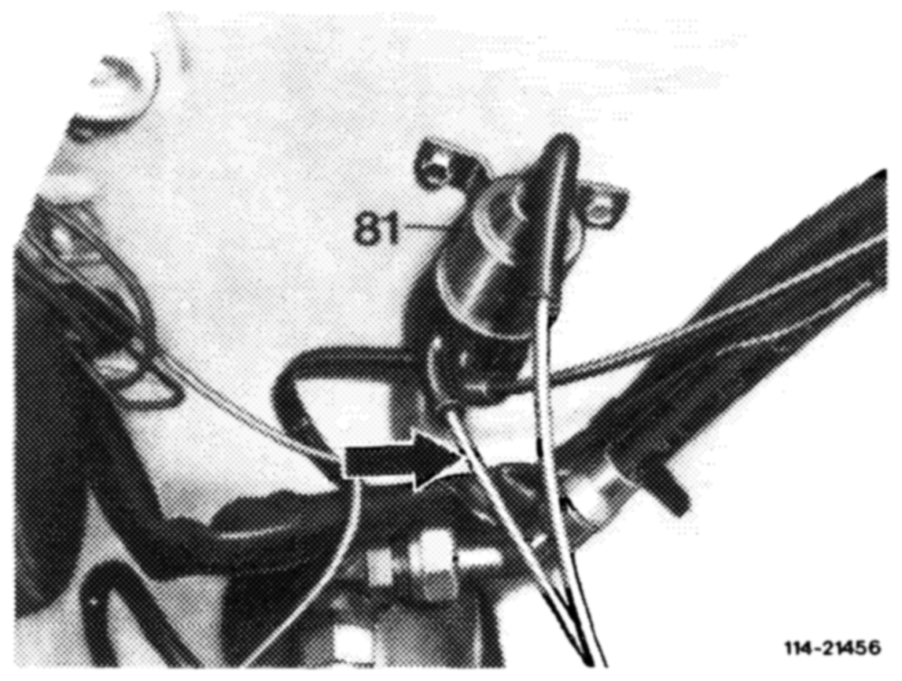
Fig. 29 Fig. 32
81 Switchover valve, electric 82 \mpulse transmitter, speedometer
Information concerning trouble diagnosis
For complaints such as:
High fuel consumption, poor performance excessive smoke and knocking at full load, check the throttle valve for proper function and free movement.
If in order, perform the test program for the emission control system.
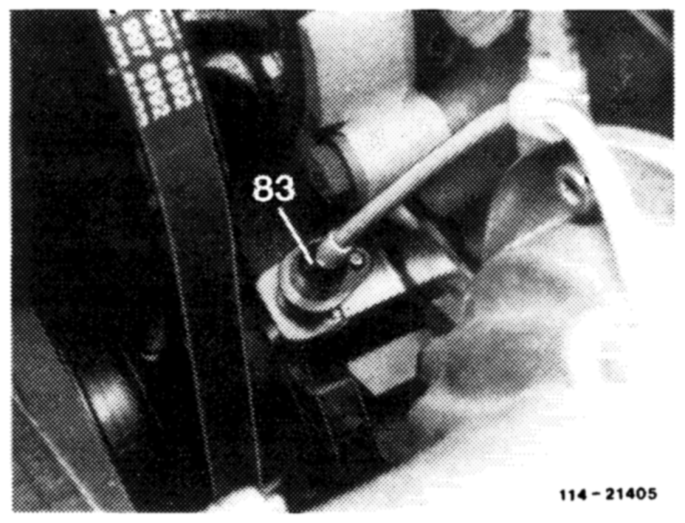
Fig. 30
83 TDC transmitter
14-100 Test program, emission control system
For complaints such as: Very poor engine performance, black or blue smoke, combustion knocking at full load, poor cold starting with smoking and rough idie.
Test conditions: Throttle linkage correctly adjusted, connect tachometer, engine at operating temperature, run engine at idle (750 + 50 rpm){idle speed control turned down), steering in straightahead position, climate contro] turned off, selector lever of automatic transmission in position ,,P’’
Tested: Exhaust gas recirculation (EGR).
Special tool
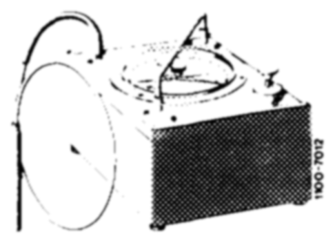
Vacuum tester 01000 mbar – 116 589 25 21 00
Commercially available tools
Tachometer, multimeter (volt-ohmmeter)
Test connection — self-made
Distributor fitting 11707801 45 a Vacuum line 4 x 1 x 40 mm
@ a
Test line 4 x 1 x 400 mm
Adjusting roller for vacuum test on vacuum contro! valve – 916 589 00 21 00
Functional diagram vacuum line layout
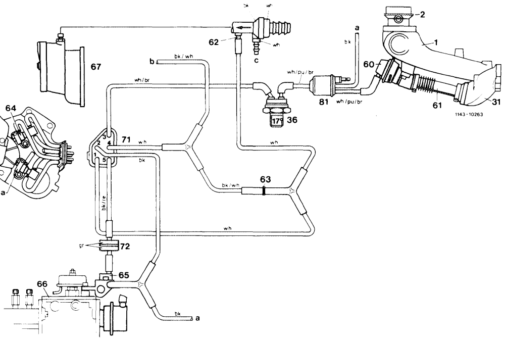
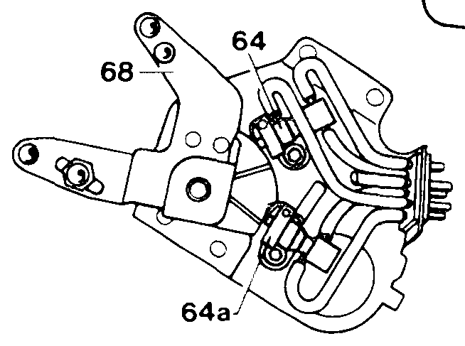
Fig. 33. Automatic transmission
1 Intake manifold 65 Vacuum control vaive Color code
2 Throttle valve housing 66 Injection pump bk = black
31 Exhaust manifold 67 Vacuum pump br = brown
36 Thermo-vacuum valve 17 °C 68 Lever with cam gr = green
60 EGR valve 71 Central plug Pu = purple
61 Corrugate tube 72 Surge damper, vacuum re = red
62 Orifice 81 Switchover valve, electric wh = white
63 Orifice
64 Switchover valve, mechanical, EGR a Vent to passenger compartment 64a Switchover valve, mechanical, b To automatic transmission automatic transmission ¢ To additional vacuum consumers
Functional diagram with manual transmission
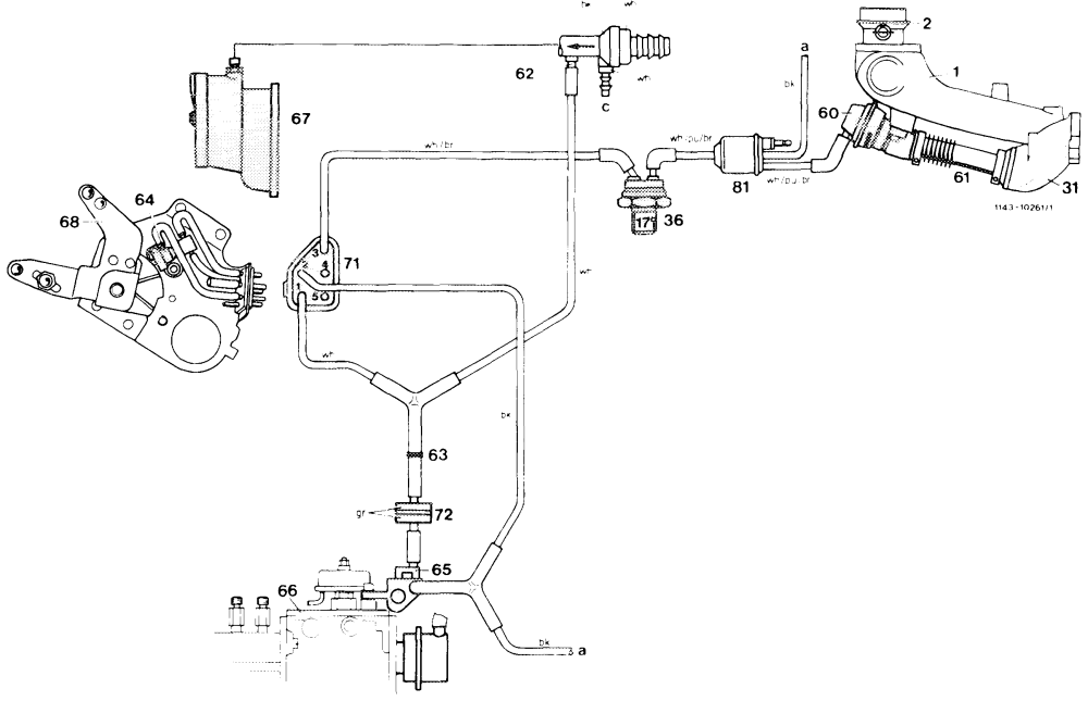
Fig. 34 Manual transmission
1 Intake manifold 66 Injection pump Color code
2 Throttle vaive housing 67 Vacuum pump bk = black
31 Exhaust manifold 68 Lever with cam br = brown
36 Thermo-vacuum valve 17 °C 71 Central plug gr = green
60 EGR valve 72 Surge damper, vacuum pu = purple
61 Corrugated tube 81 Switchover valve, electric re = red
62 Orifice wh = white
63 Orifice a Vent to passenger compart
64 Switchover valve, mechanical, EGR b To additional vacuum consumers
65 Vacuum control valve
Test
Note: The yellow orifice (63) should be installed at beginning of test.
Testing EGR
Connect vacuum gage between EGR valve (60) and electric switchover valve (81). Run engine at idle, read vacuum
No vacuum Vacuum present
Check vacuum lines
Check ali vacuum lines controlling the EGR system according to functional diagram for proper connection and correct, if required.
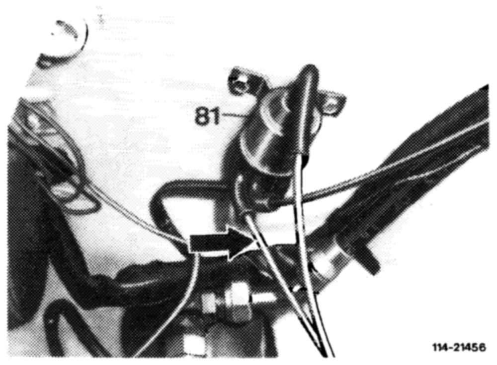
Check electric switchover valve (81)
Connect multimeter to plug of switchover valve (arrow) and measure voitage. If voltage is present, check electric wiring and components according to electric wiring diagram. !f there is no voltage, Fig. 36 replace switchover valve.
Testing EGR
Connection of vacuum tester as above. Increase engine speed to approx. 1300 rpm. Read vacuum.
Vacuum reading No vacuum or 350-500 mbar or vacuum too low
a
Check vacuum lines
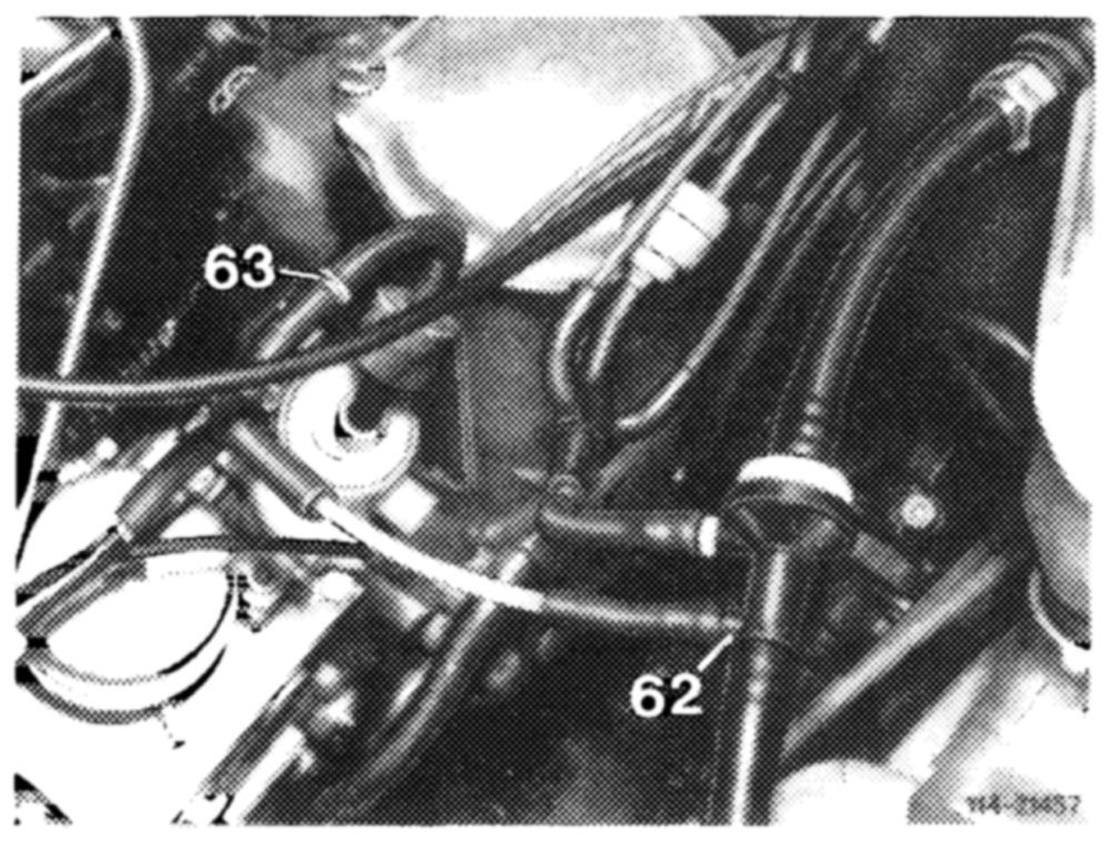
Check all vacuum lines for controlling EGR and automatic transmission according to the vacuum line diagram for correct connection and leaks. Clean orifice (62) at vacuum supply point, if required.
Check if black vent lines from vacuum control valve (65) and from electric switchover valve (81) to passenger compartment are obstructed
Check thermo-vacuum valve 17 °C
(36, color code blue)
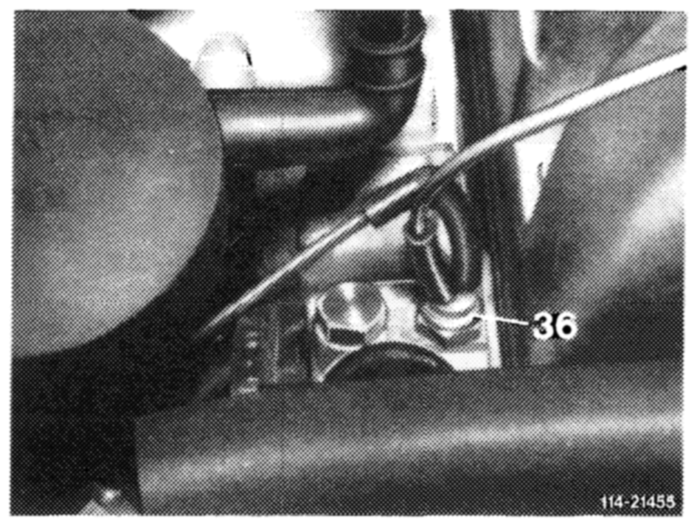
Pull white/brown vacuum line from angled connection of thermo-vacuum valve (36).
Pull white/purple/brown vacuum line from EGR valve and blow through the line.
|f you can not blow through the line, replace the thermo-vacuum valve.
Check electric switchover valve (81)
Place hand on switchover valve and run engine speed up to approx. 1300 rpm. The switchover valve should then notice- Fig. 38 ably switch
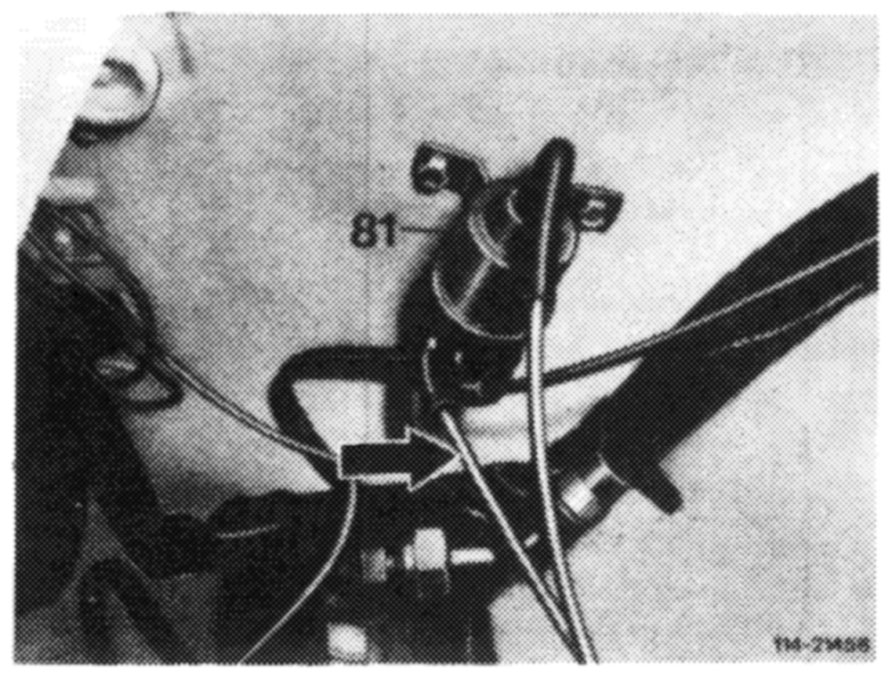
it does not switch, check electric wiring and components according to wiring diagram. Replace defective parts, if required
If it does switch, pull off vacuum line (arrow) and check for vacuum. If there is no vacuum, replace switchover valve.
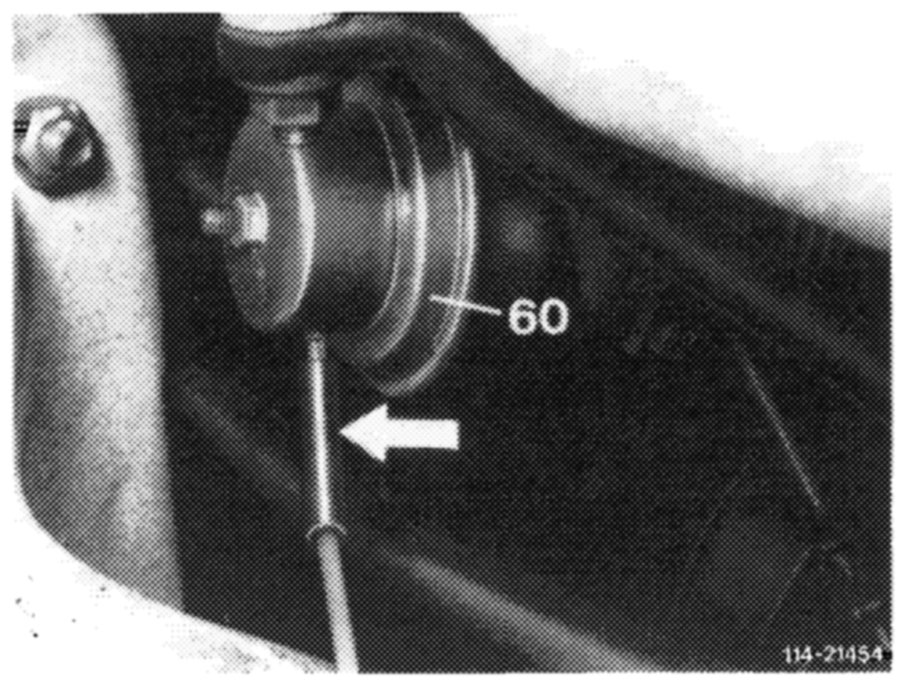
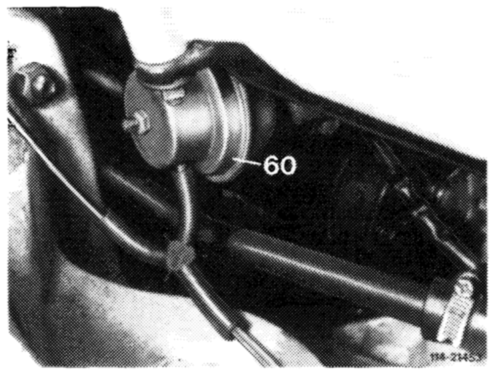
Checking EGR valve (60)
Stop engine. Connect the vacuum hand pump to the EGR valve and apply approx. 400 mbar vacuum
Pull off vacuum line.
EGR valve should EGR valve does not close audibly close audibly
Fig. 40 Replace EGR valve (60)
ae ce
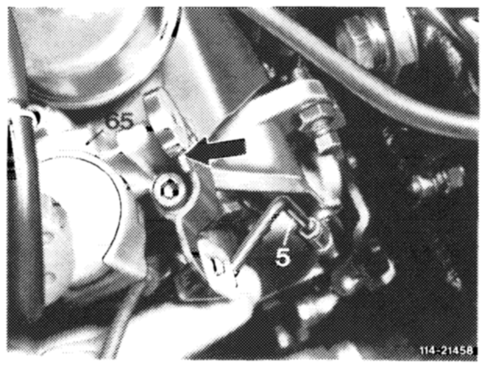
Cecking vacuum control
Connect vacuum tester between EGR valve (60) and switchover valve (81). Disconnect connecting rod (5) on ball head. Start engine and run at approx. 1300 rpm. Place adjusting roller on vacuum control valve (65) and move lever against stop (arrow). Note: Attach connecting rod at completion of test
| Vacuum reading | Vacuum above or |
| 200-240 mbar | below specified value |
| ar |
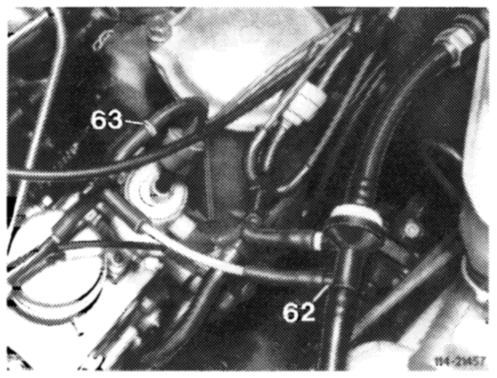
Check orifice (63)
Check orifice for unobstructed passage and blow out, if required.
If vacuum reading Is too low, install next smaller orifice. |f vacuum reading is too high and the yellow orifice is installed as prescribed for the test, replace the vacuum control valve (65). The same applies if the indicated vacuum cannot be reached using a smaller orifice.
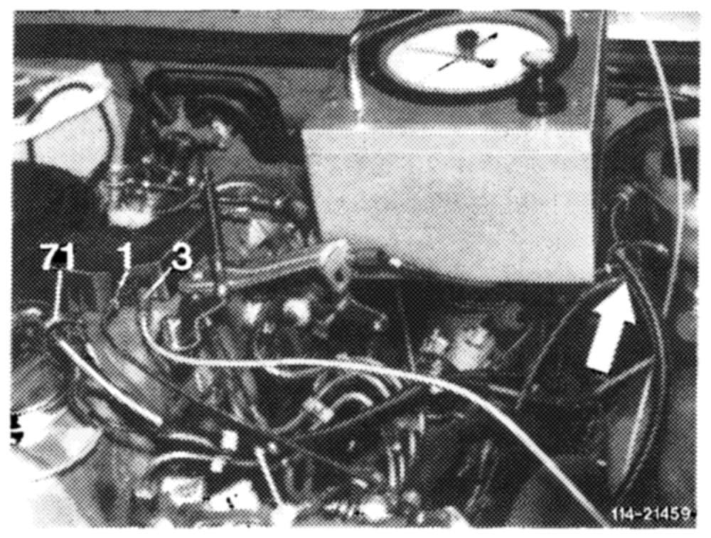
Checking full throttle shutoff
Pull off central plug (71). Connect test line between tapping point (black orifice, arrow) and valve plate connection (1). Connect vacuum tester to connection (3). Start engine and read vacuum
Readout
At idle approx. 700-800 mbar O mbar at idle
Move regulating Vacuum does not Fig. 43 linkage to full throttle drop stop O mbar
Leak test switchover valve (64)
Vacuum connection as above. Stop engine.
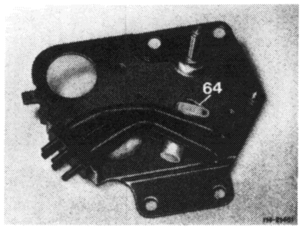
Vacuum should Vacuum drops remain constant for approx. 2 min Fig. 44 Automatic transmission
Fig. 45 Manual transmission
= =P
Checking vehicle speed shutoff
Connect vacuum tester between EGR valve (60) and switchover valve (81). Operate vehicle on dynamometer or road (not at full throttle). Read vacuum
Readout
Speed Below approx. 7348 km/h Vacuum present
Above approx Vacuum does not 73 48km/h drop O mbar
Check electric operation of switchover vaive (81). For this purpose, connect multimeter to plug (arrow) of switchover valve and drive vehicle
If voltage (approx. 12 V) is present at a speed above approx. 73 + 8 km/h, check electric wiring and components according to wiring diagram. Replace defective parts, if required.
If there is no voltage, replace switchover valve
End of test
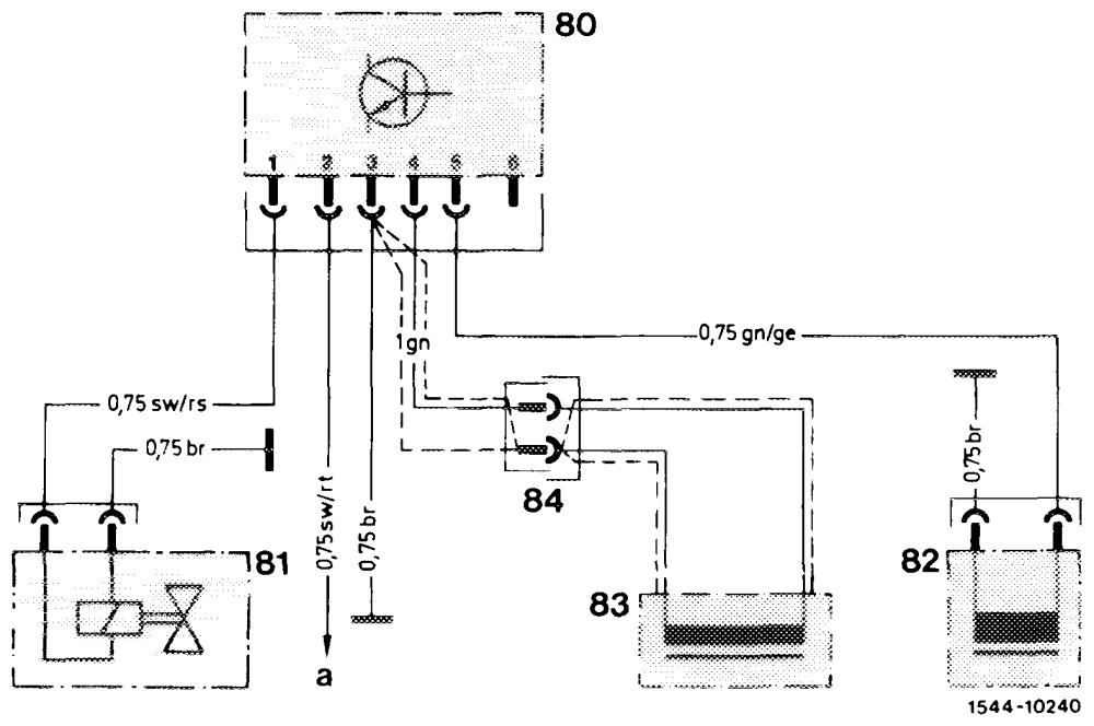
Electric wiring diagram, EGR
Fig. 48
80 Control unit 81. Switchover valve, electric
82 Impulse transmitter, speedometer
83 TDC transmitter
84 Coupling TDC transmitter a = termina! 15, fuse 14
Throttle control linkage on engine Throttle control linkage on chassis
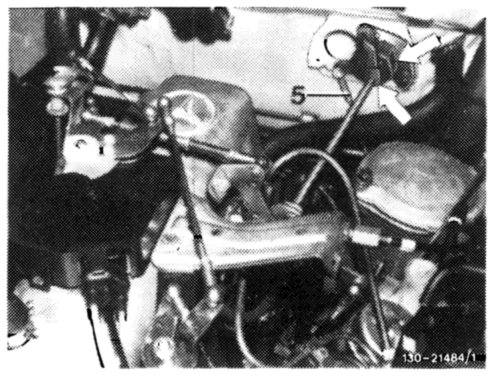
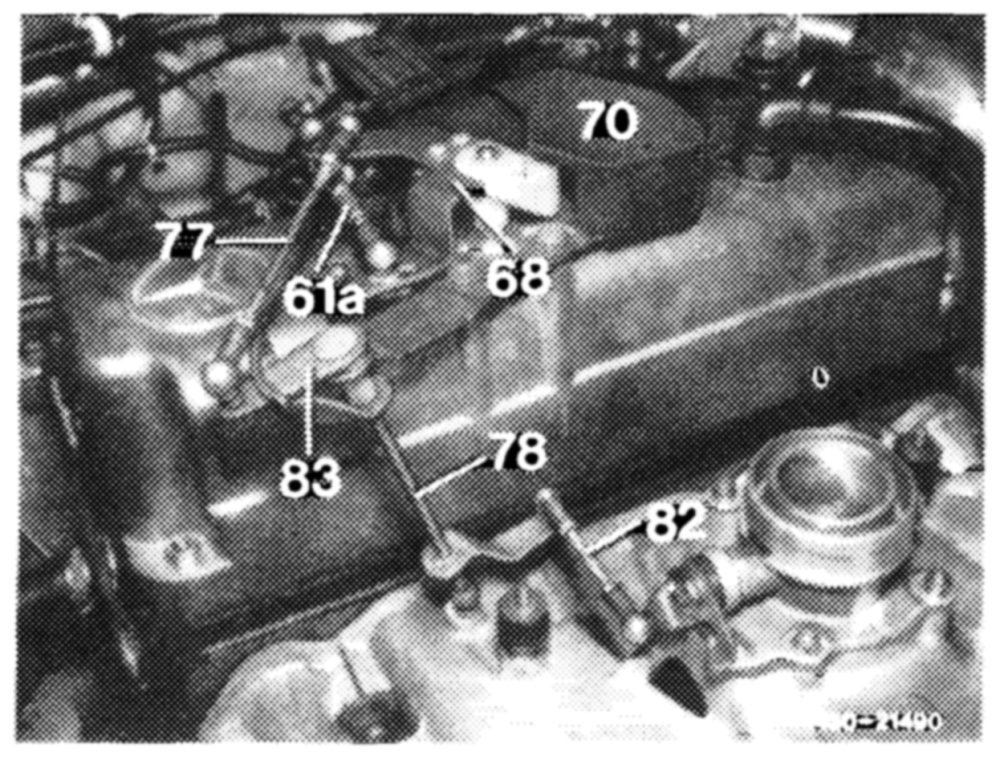
Additional throttle linkage components are required A spring washer and a graphite washer with copper for controlling EGR. mesh are installed instead of the plastic ring (arrows).
Fig. 50
Throttle control linkage adjustment
Length of control rods
Connecting rod (82), throttle valve 94 mm Telescoping rod (60) in extended condition 154 mm Pull rod (61) 137 mm Spring loaded telescoping rod (61a), manual transmission 154 mm Push rod (5) 186 mm Pull rod (77)* 186 mm Push rod (41)* 184 mm
*) Basic adjustment
Special tool (spare part)
Adjusting sleeve 180 072 03 93
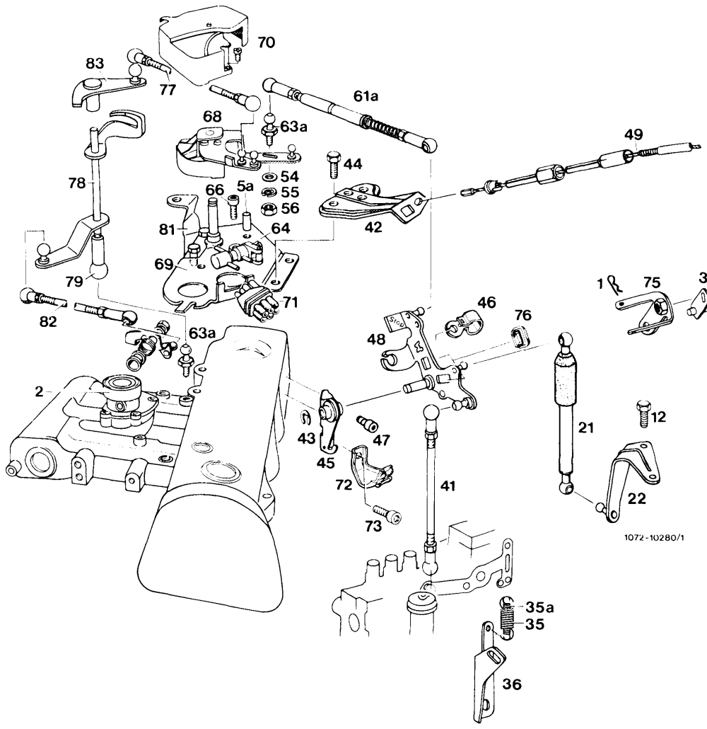
Fig. 51. Vehicle with manual transmission Safety ciip 43 Retaining ring 71 Central plug NOOBWNThrottie vaive housing (EGR) 44 Hex. head screw Holder Longitudinal control shaft 45 Bearing 73 Hex. socket head screw Adjusting screw 46 Special form spring 75 Drive lever Stop bolt 47 Hex. socket head screw 76 Plastic bushing Washer 48 Angle lever 77 Pull rod Shaft Hex. head screw 49 Idle speed adjustment cable 78 Damper 6la 21 a Spring-loaded telescoping rod 79 Ball socket Hotder 63a Shaft holder 22 Ball head 81 Compression spring, external Switchover valve, mechanical 82 Connecting rod, 35 35a Compression spring, internal Lever with cam throttle valve housing Push rod 83 Drag lever Valve mounting plate 42 Holder Cap
Throttle control linkage on engine
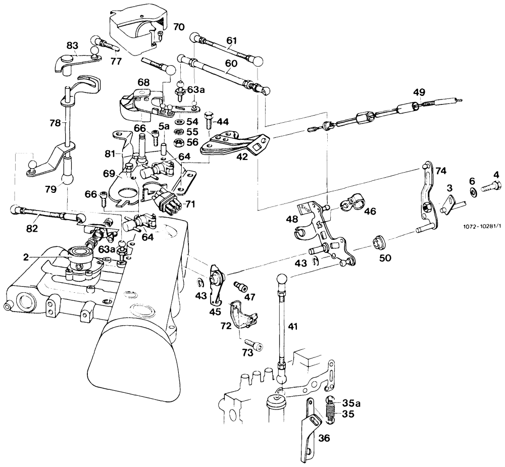
Fig. 52 Vehicles with automatic transmission
2 Throttle vaive housing (EGR) 48 Angie iever 71 Central plug
3 Longitudinal control shaft 49 idie speed adjustment cable 72 Hoider
4 Adjusting screw 50 Plastic bushing 73 Hex. socket head screw 5a Stop bolt 60 Telescoping rod 74 Guide lever
6 Washer 61 Pull rod 77°) “Pull rod
41 Push rod 62 Hex. head screw 78 Shaft
42 Holder 63a Ball head 79 Ball socket
43 Retaining ring 64 Switchover vaive, mechanical 81. Shaft holder
44 Hex. head screw 66 Hex. socket head screw 82 Connecting rod,
45 Bearing 68 Lever with cam throttle valve housing
46 Special form spring 69 Valve mounting plate 83 Drag lever
47 Hex. socket head screw 70 Cap
Chassis regulation
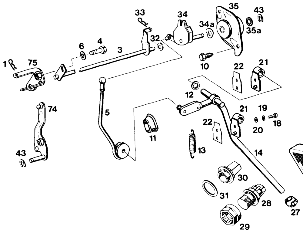
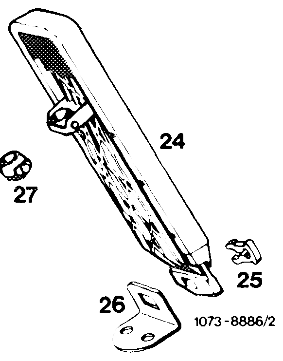
Fig. 53
1 Safety clip, manual transmission 20 Washer 34 Control tever with damper
3 Longitudinal control shaft 21 Bearing 34a Wave washer
4 Adjusting screw 22 Gasket 35 Bearing holder
5 Push rod 24 Accelerator peda! 35a Graphite washer with
6 Washer 25 Clip copper mesh
10 Screw 26 Mounting bracket 43 Safety clip
11 Rubber grommet 27 Swivel joint 74 Guide iever,
12 Plastic spacing ring 28 Kickdown switch, autom. transmission automatic transmission
13 Return spring 29 Adjusting nut, autom. transmission 75 Drive lever,
14 Accelerator lever 30 Full throttle stop manual transmission
18 Hex. head screw 31 Washer
19 Wave washer 33 Safety clip
Adjustment
1 Check contro! linkage for binding and distortion. Replace damaged parts, if any
2 Disconnect spring-loaded telescoping rod (23) (cruise control) or connecting rod (22) and idle speed control cable
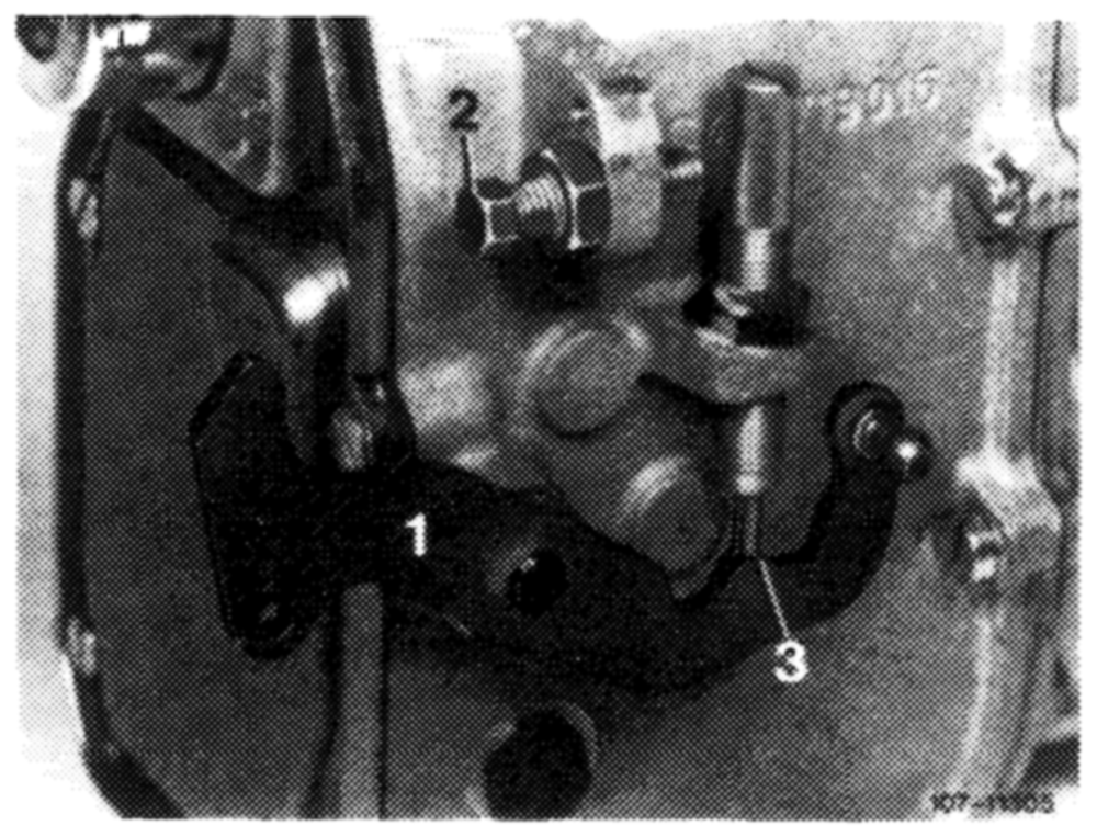
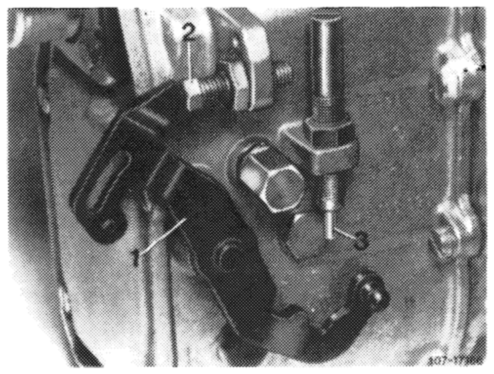
3 Check whether control lever (1) of injection pump rests against idle speed stop (3).
Fig. 54 1 Control lever 2 Full throttle stop 3 Idle speed stop
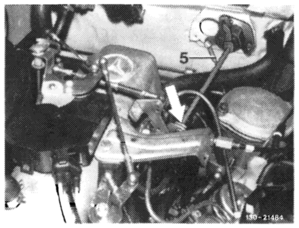
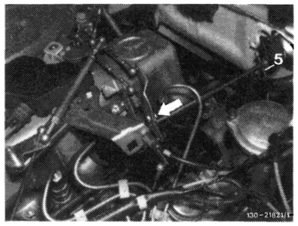
4 Check adjustment of connecting rod (5). For this
Vehicles with manual transmission
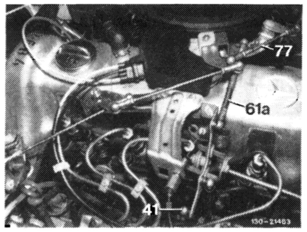
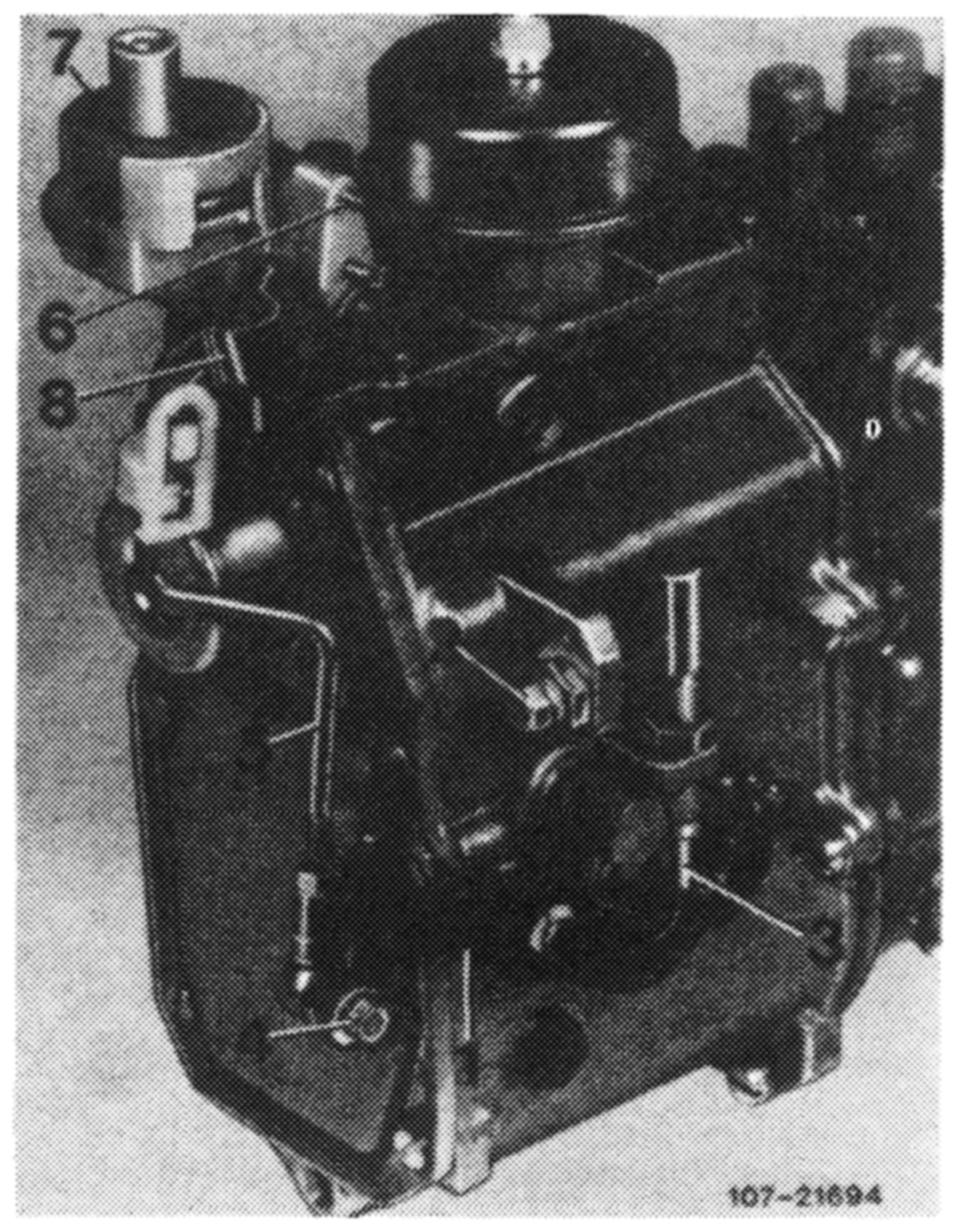
purpose, move control lever (1) to full throttle stop (2), making sure that a clearance of less than 0.5 mm 5 Check spring-loaded telescoping rod (61a) for is available between lever (8) and stop (6). If required, 154 mm length and adjust, if required. adjust connecting rod (5) with adjustable ball head (4).
Fig. 56 41° Push rod 61a Spring loaded telescoping rod
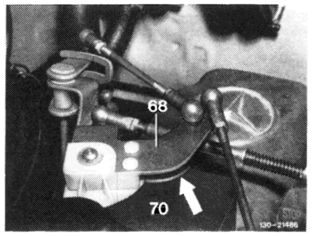
6 Check whether sever with carr (68) is in alignment with mark (arrow! of cap iseen from above}. Adjust push rod (41! if required
Fig. 55
1 Contro: lever 6 Full throttle stop on
2 Full throttle stop on vacuum contro! valve injection pump 7 Vacuum contro! vaive 3. Idle speed stop 8 Actuating lever for
4 Adjusting bai! head vacuum control valve
5 Connecting rod
Fig. 57 68 Guide lever 70 Cap
9 Connect idle speed adjustment cable free of
7 Install adjusting sleeve (05) to stop bolt of valve mounting plate (69). tension
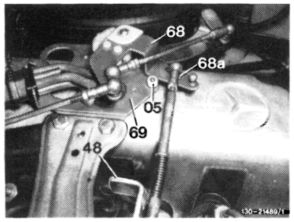
Pull angie lever (48) to full foad, with contro! lever ( 7} 10 Check full throttle stop. With engine stopped on injection pump resting against full load stop (2) depress accelerator peda! from inside vehicle against In this position, lever with cam (68) should rest against stop. Control lever {1} should rest against full throttle adjusting sleeve (05). If required, adjust adjustable ball stop (2) of injection pump. Adjust control linkage head (68a) in slot with adjusting screw (arrow) if required
Fig. 58 Fig. 60
05 Adjusting sieeve 68 Lever with cam 1 Controi tever 3 Idie speed stop
48 Angie lever 68a Adjustable bali head 2 Full throttle stop
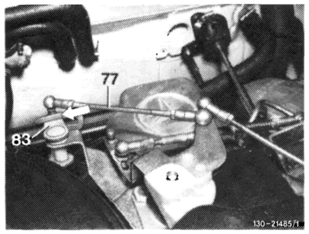
8 Set drag iever (83) to mark (arrow). Set pull rod 7 11. If the full throttle or idle speed stop (2 or 3) is (77) to mark and connect. not attained with this adjusting screw, adjust push rod 5) from longitudinal control shatt to lerator IOC pedal to specified length measured from center of damping ring and connect.
Fig. 59
83 Drag lever 77° Pull rod
Fig. 61 Note: Throttle valve position. at idle = horizonta full load = vertical
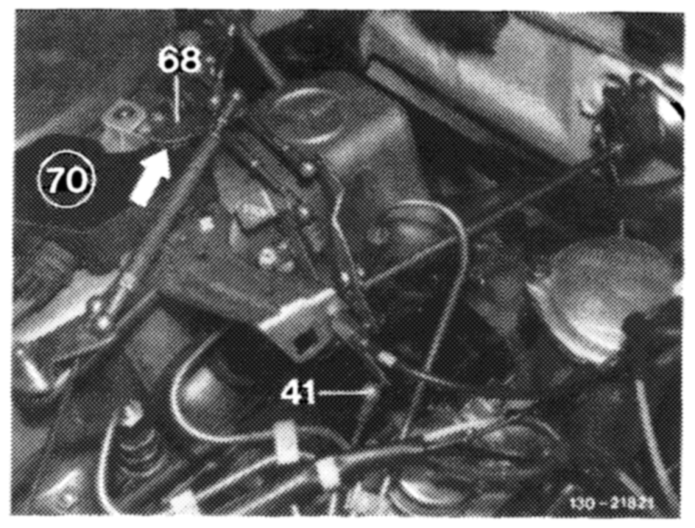
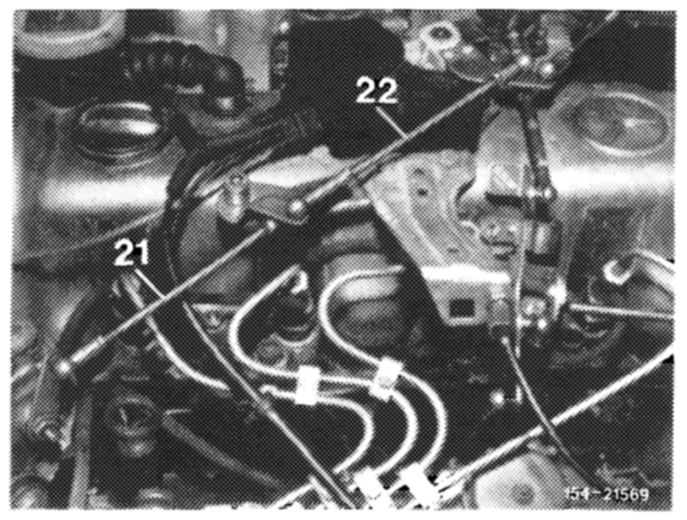
12. Check connecting rod (22) to cruise control for 14 Check whether lever with cam (68) is in alignment specified length of 178 mm and adjust, if required with mark (arrow) of cap (70) and adjust push rod Disconnect connecting rod (21) on actuator. Check (41), if required, if throttle control linkage is in idle speed position. Push lever of cruise control actuator clockwise to idle speed position. Check whether connecting rod (21) is 1 mm longer than the actual distance and adjust, if required. Attach connecting rod (21)
Fig. 64 41 Push rod 70 Cap 68 Lever with cam
Fig. 62 15 Plug adjusting sleeve (05) on stop bolt of valve mounting plate (69). Pull guide lever (74) to full ioad, 21) Connecting rod 22 Connecting rod = 178 mm the control ‘ever (1) of injection pump must rest against full load stop (2). In this position, lever with
Vehicle with automatic transmission
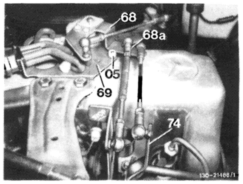
cam (68) should rest against adjusting sieeve (05), adjust adjustable ball head (68a) in slot, if required 13) Check telescoping rod (60) and pull rod (61) for specified length and adjust, if required.
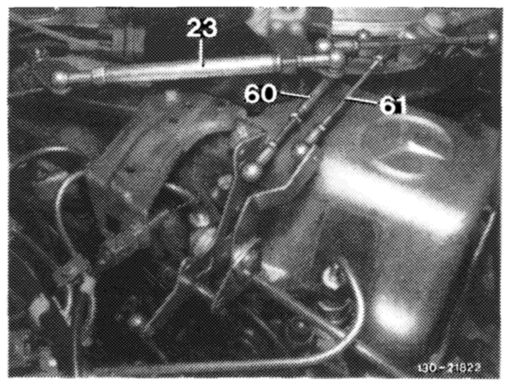
Note: Telescoping rod (60) 6 mm extended
Fig. 65 05 Adjusting sieeve 68a Adjustable bal! head 68 Lever with cam
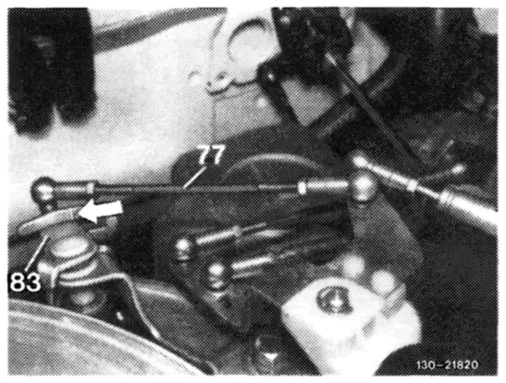
16 Set drag lever (83) to mark (arrow). Set pull rod (77) to mark and connect
Fig. 68
Fig. 66 20 Check spring-loaded telescoping rod (23) to 77° Pull rod 83 Drag lever cruise control for specified length (178 mm)
Disconnect connecting rod (21) on actuator 17. Connect idle speed adjustment cable free of tension Check if throttle control linkage is in idie speed posi tion. Push lever of cruise control actuator clockwise
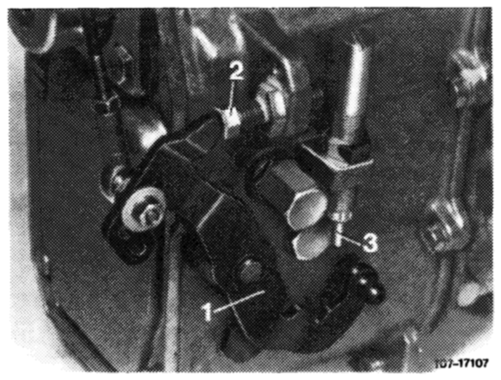
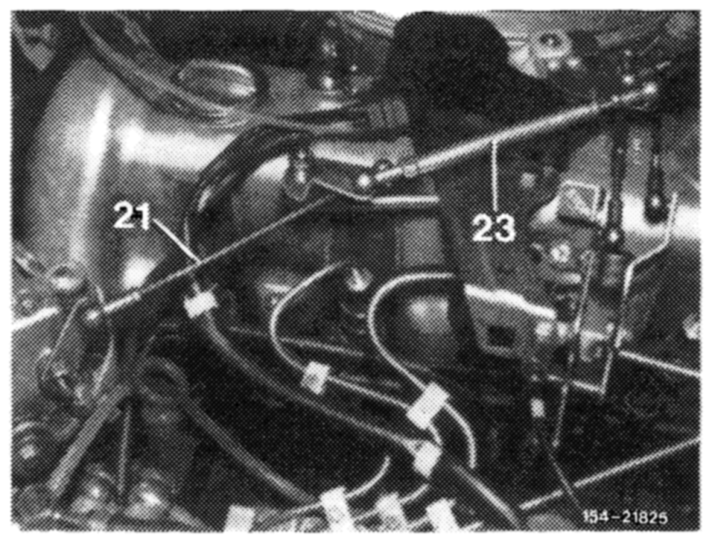
18 Check full throttie stop. With engine stopped, to idle speed position depress accelerator pedal from inside vehicle to kickdown switch. Control lever (1) should rest against Check whether connecting rod (21! 1s 1 mm longer full throttle stop (2) of injection pump. Adjust than the actual distance and adjust, if required control rod with adjusting screw (arrow), if required. Attach connecting rod (21).
Fig. 67 Fig. 69
1 Control lever 3. Idle speed stop 21 Connecting rod
2 Full throttle stop 23 Spring loaded telescoping rod = 178 mm
19 Jf full throttle or idle speed stop is not attained with this adjusting screw (arrow), adjust push rod (5) from longitudinal control shaft to accelerator pedal to specified length, measured from center of ball socket to center of damping ring and connect