Retrofitting engine shock absorber (engine model 617 in type 123.1)
WIS 00-242
Tightening torques
Nm (kpm)
| Bolts for engine bearer at engine mount front | 70 40 | (7) (4) |
| Bracket to oil pan | 25–35 | (2.5–3.5) |
| Bolts for rear engine mount at engine bearer | 25 | (2.5) |
| Nut (transmission to engine mount — reference value) | 70 | (7) |
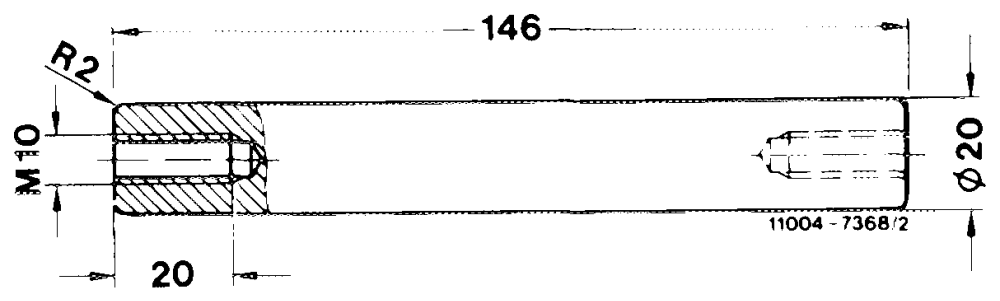
Special tools
Torque wrench handle 20-100 Nm (2–10 kpm) – 001 589 35 21 00
Attachable ratchet, 1/2’ drive for torque wrench handle – 001 589 42 09 00
Note Vehicles with end chassis Nos. upward of those listed below feature two engine shock absorbers:
Type End chassis No.
123.105 108 728 123.130 108 309 123.132 108 728 123.150 002 875 123.190 000 087 et on the oil pan and the crossmember.
If a vehicle with a lower end chassis No. is brought in on account of stuttering, idling vibration or drumming at low revs in neutral, it can be retrofitted with the engine shock absorbers.
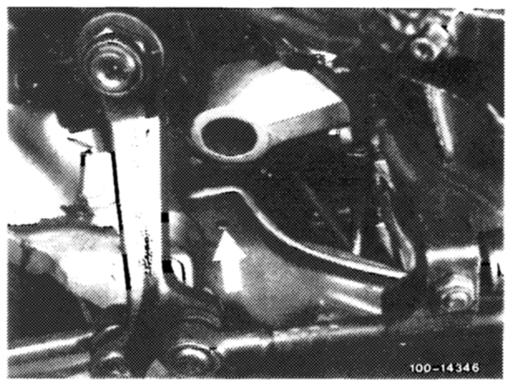
In cases where just one engine shock absorber is fitted, this has to be removed first.
Spare parts
Qty. Part Part No.
1 Repair set Engine shock absorber 123 586 02 24 consisting of:
1 Bracket (oil pan) 123 240 02 40
1 Bracket, left (crossmember) ’) 123 620 13 14
1 Bracket, right
(crossmember)’? 123 620 1414
2 Engine shock absorber 123 240 09 48
8 Rubber buffer 123 241 00 65
2 Washer 123 241 06 76
4 Disk washer 123 241 0312
4 Nut 913002 006005
2 Screw assembly M8 x 30 914019 008003
2 Washer 8.4 000433 008406 Engine mount, rear 115 240 22 187) Supporting plate 108 242 00 317)
Where available: Works 10 (ET Esslingen-Mettingen) 1) Works 50 (ET Sindelfingen). 2) Only for models with manual transmissions.
Installation
1 Turn steering to full left or right lock.
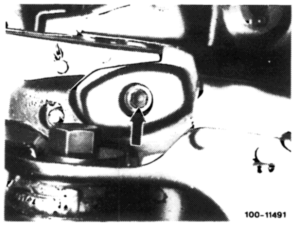
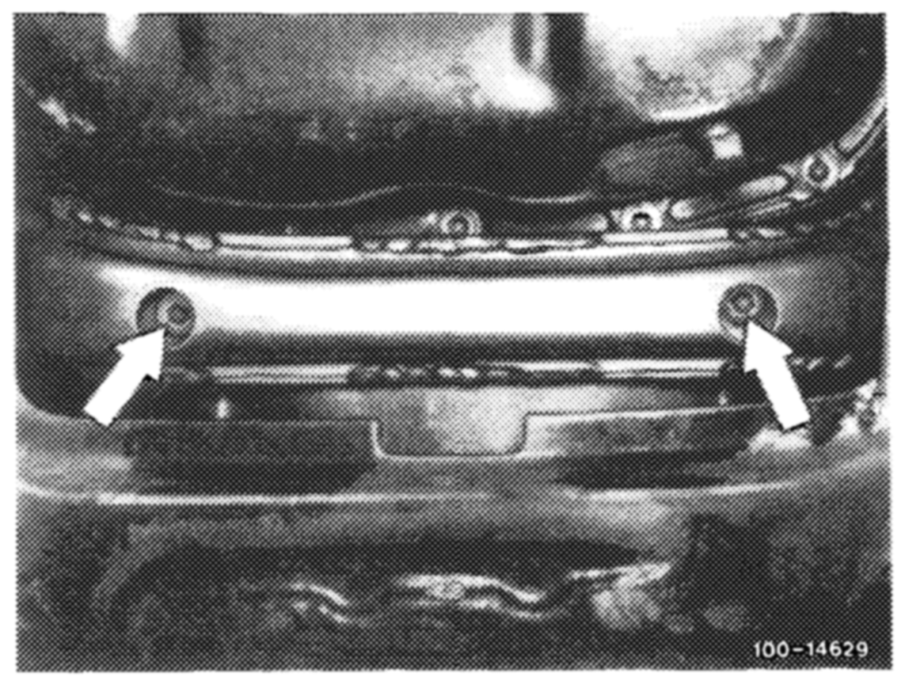
2 Remove engine bearer bolts at engine mount, working from below (arrow).
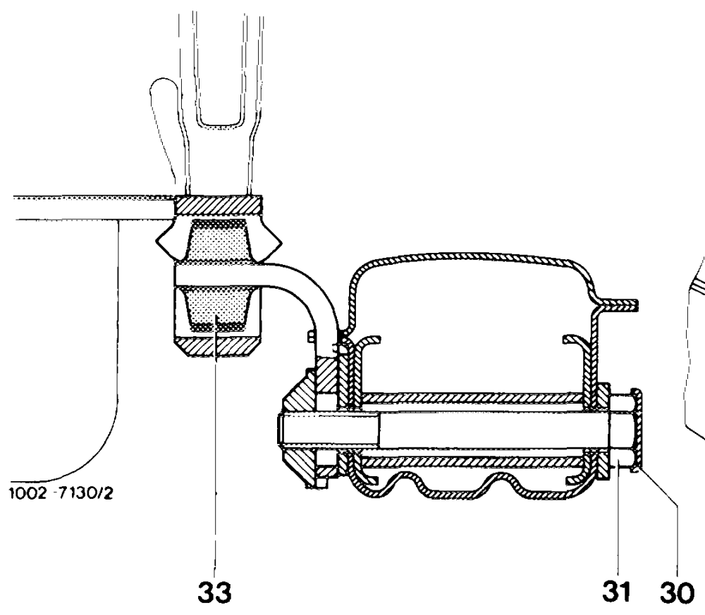
3 Lift up retainer (30) at front engine stop, swing away to one side and remove adjusting screw (31).
4 If only one engine shock absorber is fitted, first remove this absorber.
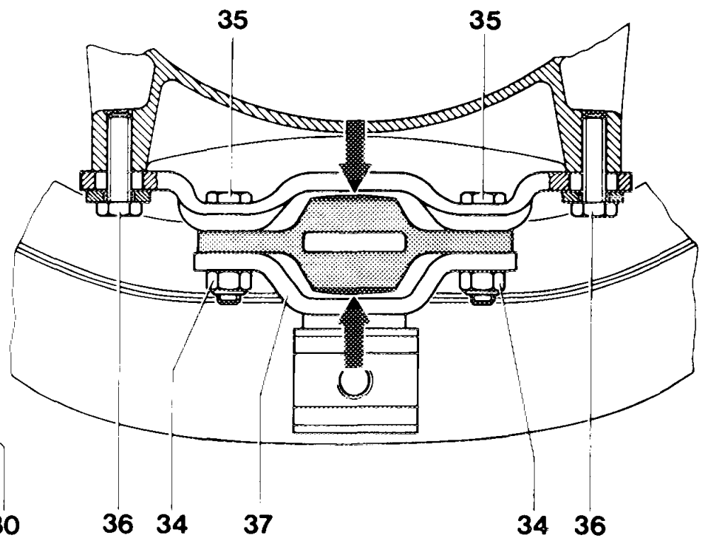
5 Unscrew bolts (36) in oil pan and fully withdraw engine stop.
41 +
6 Raise engine, applying inspection pit lift to oil pan or attaching a crane to front suspension lug on cylinder head. Lift up by such an amount that front engine -10- ! mounts can be removed. NN
7 Remove front engine mounts.
fe 115 – _
8 Install shop-made, rigid engine mounts. ~_ —94+05 a
30
Rigid engine mount
gine mount. Do not tighten.
10 Bolt bracket (43) to oil pan (60).
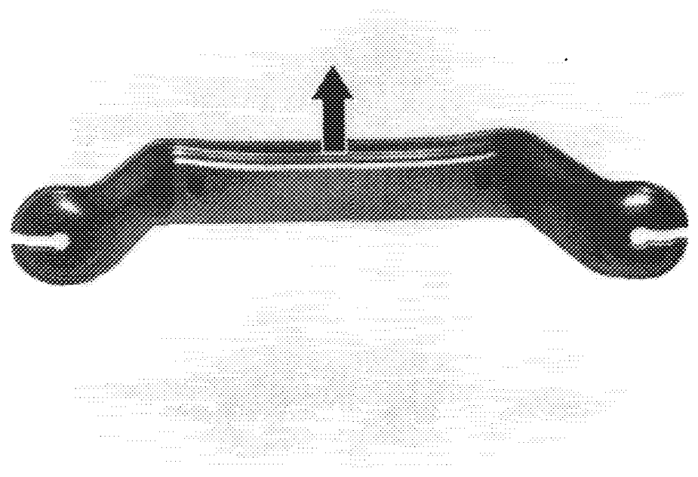
Note correct mounting location. The concave side of the bracket must point toward lower part of oil pan (straight-ahead) (arrow).
Wr SIT
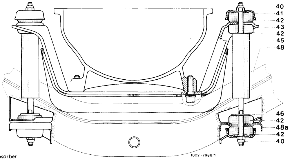
36 Bolts M8 x 30 40 Nut M6 41 Disk washer 42 Rubber buffer 43 Bracket 45 Engine shock 46 Washer 48 Crossmember 48a Bracket 60 Oil pan
left-hand side in straight-ahead direction.
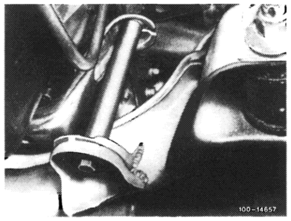
Welding gauge EE 2D snsoxz0 cH
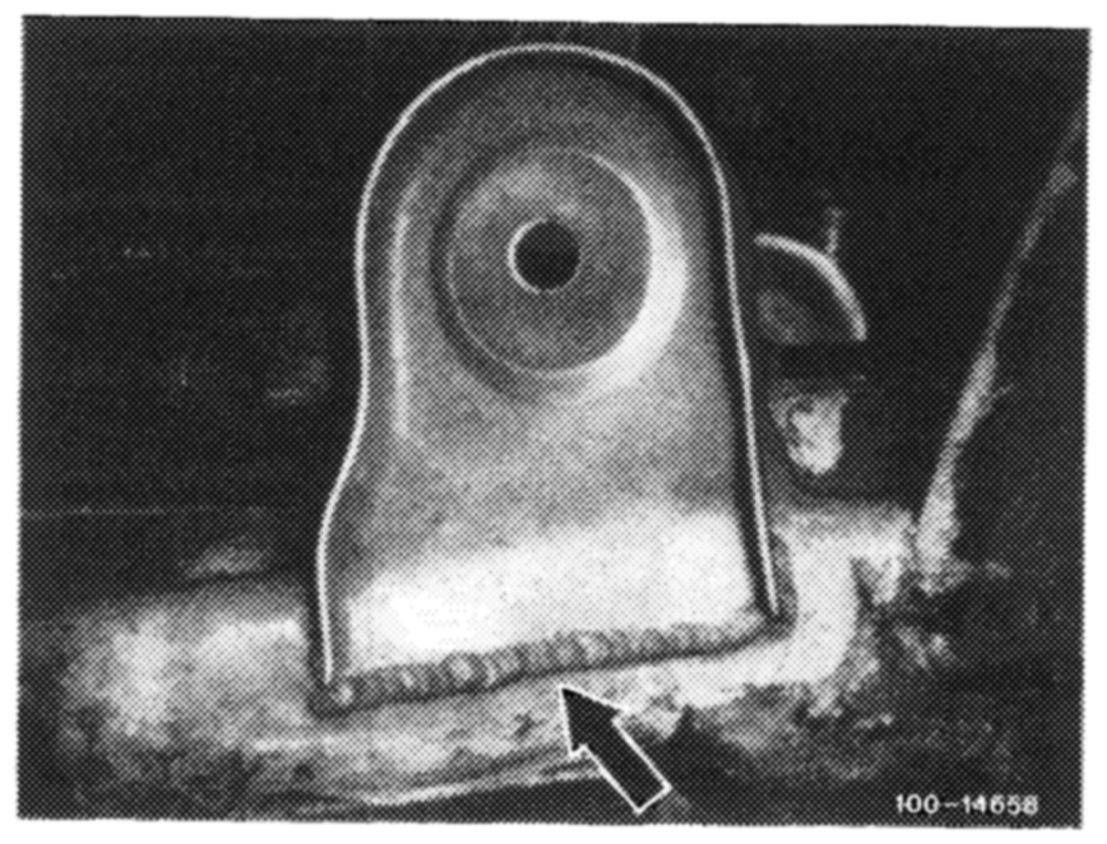
12 Remove paint from crossmember (48) in region of bracket (48a) that is to be welded in position.
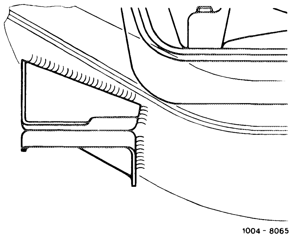
13 Bolt bracket (48a) to welding gauge and weld to crossmember. See illustrations for welding locations.
Be sure to use nothing but inert-gas welders.
14 Remove welding gauge.
15 Bolt welding gauge to bracket at right-hand side in straight-ahead direction.
16 Repeat jobs 12-14.
17 Remove rigid engine mounts.
correctly located.
19 Insert and tighten engine bearer bolts at engine mount.
20 Apply primary and finishing coats of paint to welded brackets.
21 Install engine shock absorber with reference to illustration.
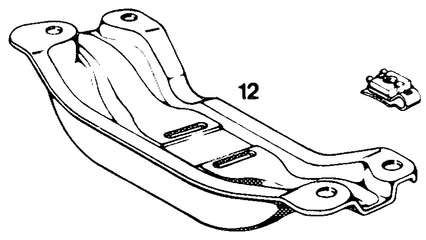
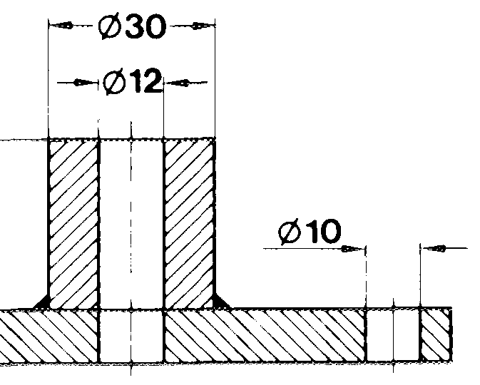
22 The crossmember hole where the engine stop was bolted on is now to be filled and covered with an M 12 x 95 bolt, two washers and a nut to stop corrosion. Position retainer on bolt head.
23 |f model has manual transmission and has not yet featured an engine shock absorber, first remove rear engine mount (4) with bracket.
<7 {hw 4 Engine mount 8 Bracket
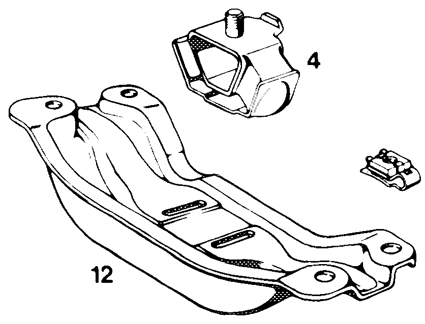
24 Install new engine mount as per part No. 115 240 22 18, referring to illustration. Prior to depositing transmission on engine mount, place supporting plate (3) on engine mount (4).
© 6 713 3 Supporting plate 1004-7321 & 4 4 Engine mount