Removal and installation of piston
WIS 03-316
Piston/cylinder allocation
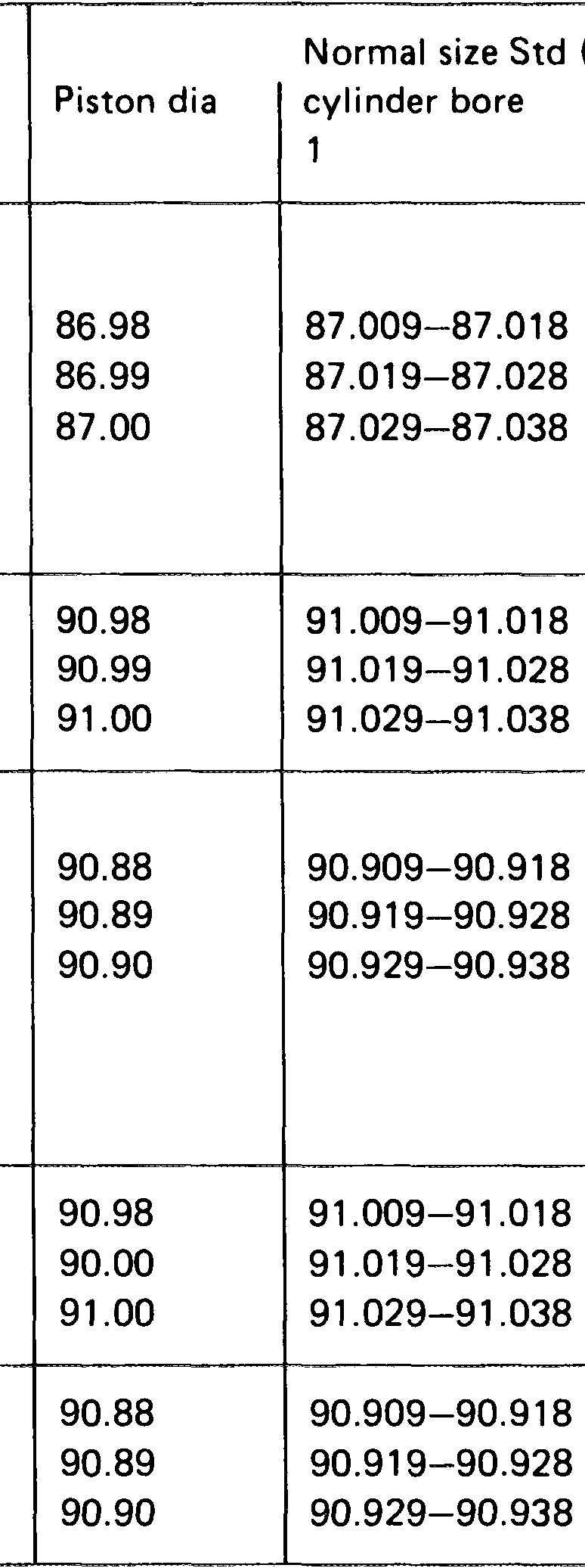
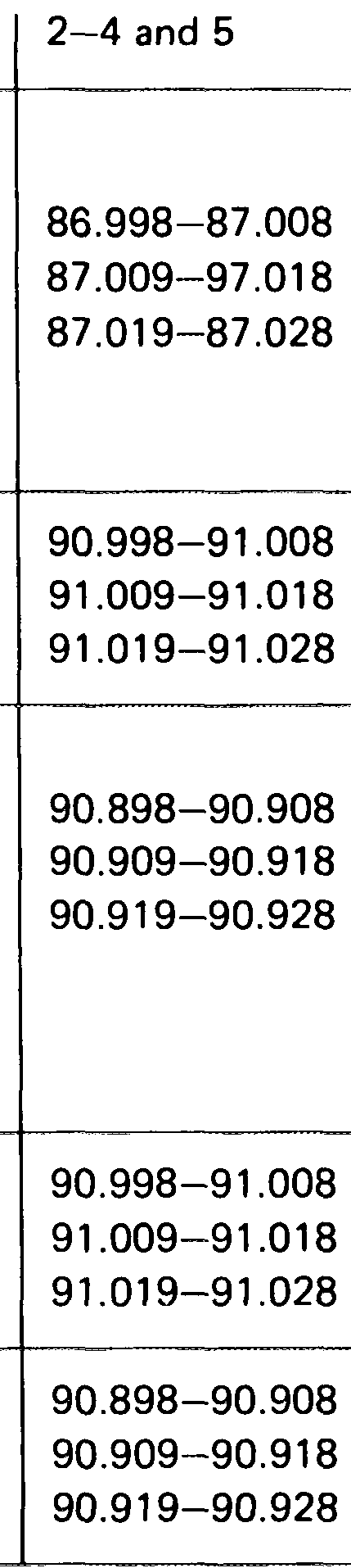
(standard) Group
1
26), 27!)
1
1
1 2
1) Only for cylinder liners of low carbon content (see note)
Piston projection
Distance between piston crown Engine and crankcase parting surface Projection min. Projection max.
615.912/940 0.50 0.90 615.913/941 0.65 1.05 616, 617 0.50 0.90
Piston play 0.12
5g Difference in weight between any two pistons in one engine 109
25.995–26.000 Piston pin diameter
in small-end bushing 0.012–0.023 Piston pin play in piston 0.00–0.01
0.20–0.40 1.5 Groove 1 End clearance of piston rings Groove 2 0.20–0.40 1.0 Groove 3 0.25–0.40 1.0
0.2
Groove 1
0.100–0.132 0.15 Side clearance of piston rings Groove 2 0.070–0.102 0.030–0.062 0.1 Groove 3
1) Cylinder No. 1 = 0.029–0.048.
Tightening torque
40–50 Nm (4–5 kpm) Initial torque Clamp nuts 90–100° Final torquing angle
Special tools
Piston ring expander – 000 589 51 37 00
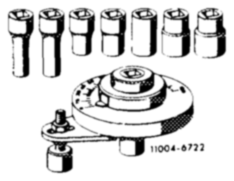
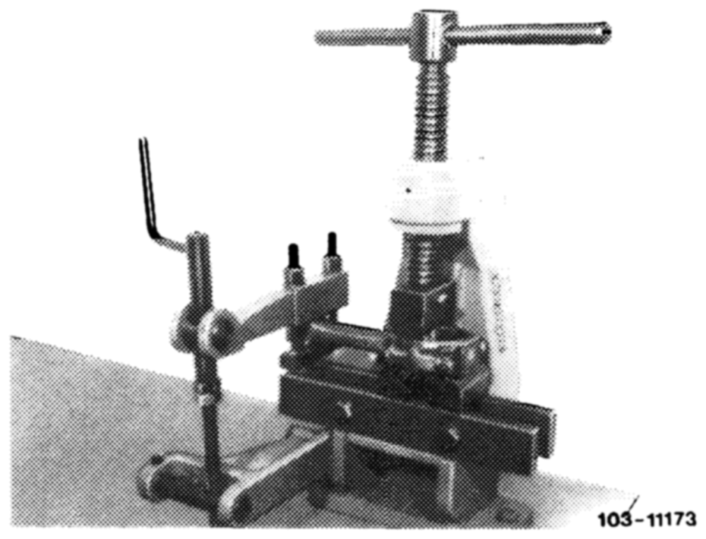
Piston ring compressor 000 589 04 1400
Torquing angle set – 116 589 01 13 00
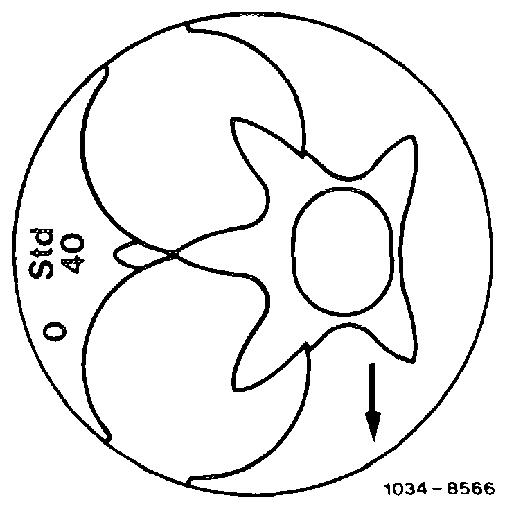
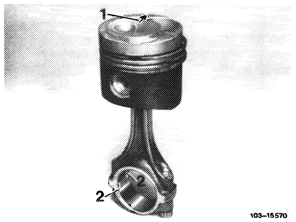
Note Group Nos. 0, 1 or 2, the piston code (e. g. 40), and the straight-ahead arrow are stamped in the piston crown.
The group No. is additionally stamped in the crankcase parting surface.
Both group Nos. (cylinder bore and piston) must agree.
This rule does not apply to cylinder No. 1 where the piston play is 0.01 mm greater. A bore bearing code No. ‘1°’ will accept a piston with code No. “’0’’ — or a bore bearing code No. ”2” a piston with code No. aye.
The piston play specification is thus met.
In the event of repair the cylinder bores are to be honed to the dimensions of the existing pistons, plus the allowance for the piston play.
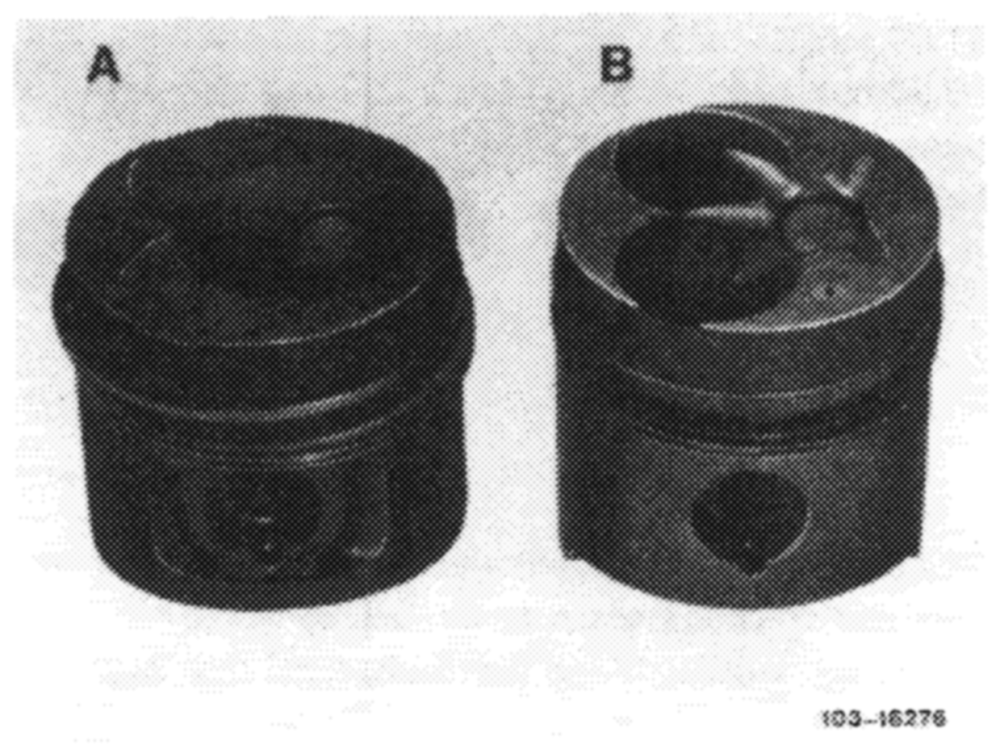
In order to confine the compression tolerance for engine model 615.940, the pistons with round combustion chamber cavities have been replaced by types with star-shaped cavities and flat precombustion chamber recesses (B).
Introduced starting end chassis No. 097 064.
In the event of repair these pistons may be installed in engines with older Nos.
A Piston with round combustion chamber cavity B_ Piston with star-shaped combustion chamber cavity
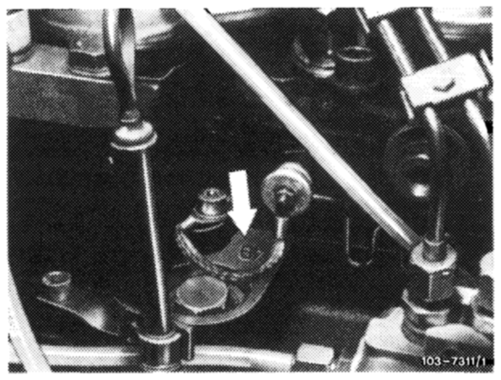
In engine model 615.912, the piston bearing code No. 26” must not be used in cylinder liners of low carbon content.
These engines are identified as follows:
The code No. ‘4 B” is stamped in the metal adjacent to the thrust piece for the rev counter connection.
The cylinder bore of engine models 616 and 617 has been reduced from 91.00 mm to 90.9 mm, starting August 1978. This modification has been made to account in a variety of countries for road taxation by engine capacity.
The corresponding pistons have a diameter of 90.9 mm.
These pistons are to be identified by the code Nos. stamped in the piston crown (see table).
may be installed in older engines, provided the cylinder bore allows.
Introduction of 90.90 mm cylinder bore
Type End chassis No. 123.102/103/123/125 084808 (@s4 085 150) 123.183 000766 123.105/130/132 105701 123.150 002839 123.190 000680
91.00 mm diameter pistons must not be used in 90.90 mm cylinder bores, and 90.90 mm diameter pistons must not be fitted in 91.00 mm cylinder bores.
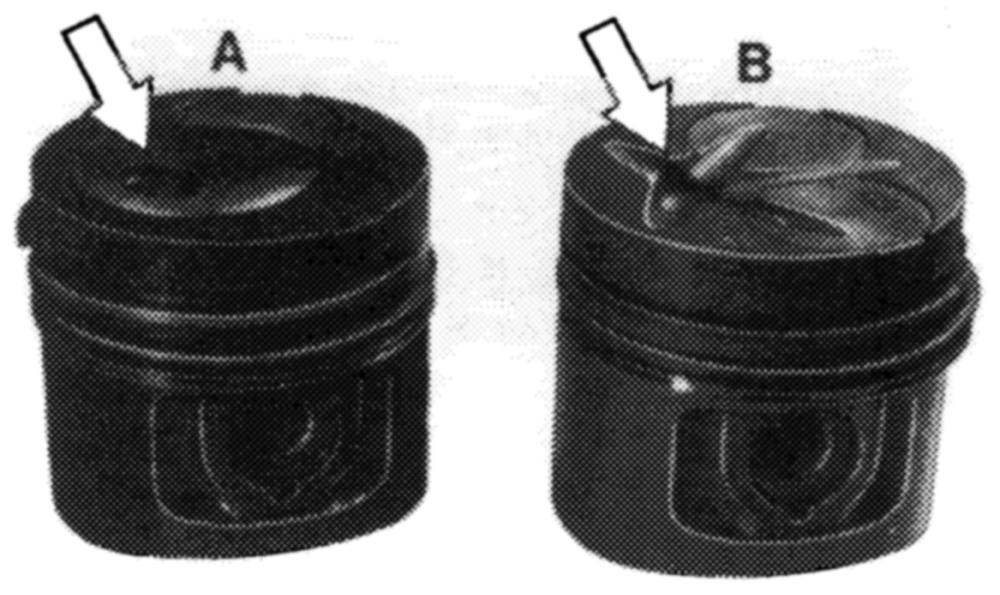
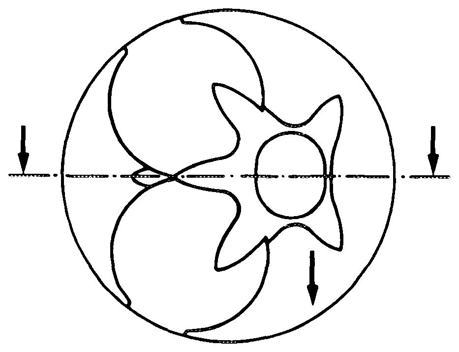
The pistons of the uprated engines have a star-shaped combustion chamber cavity (arrow, B) in the piston crown and a deep, round precombustion chamber recess (D).
A Piston with round combustion chamber cavity B Piston with star-shaped combustion chamber cavity 103~-15528/1
The standard power engines feature pistons with round combustion chamber cavities (arrow, A) and engine model 615.940 incorporates pistons with star-shaped combustion chamber cavities and flat precombustion chamber recesses (C).
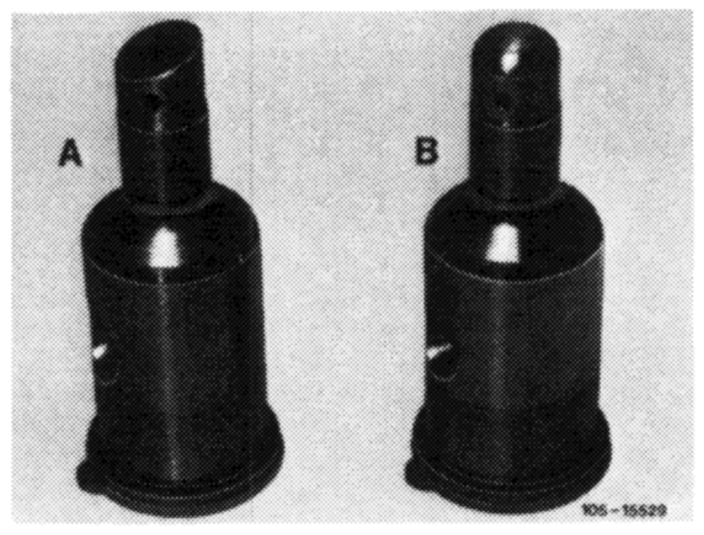
Precombustion chambers with slanting tips (A) must not be used in uprated engines because they would strike the precombustion chamber recess.
For the same reason, the precombustion chambers of uprated engines (round tip, B) must not be fitted in engines with pistons featuring round combustion chamber cavities.
Removal
1 Remove connecting rod and piston in upward direction.
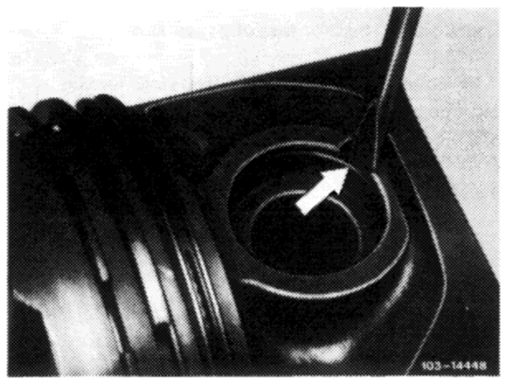
2 Remove piston pin retainer and force piston pin out.
Installation
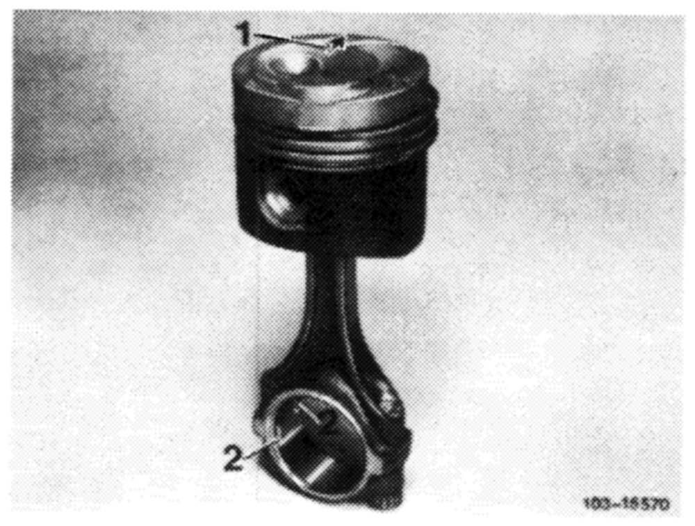
4 Position piston on connecting rod so that arrow (1) points straight-ahead and retainer grooves (2) in connecting rod are at left-hand side of engine.
Caution:
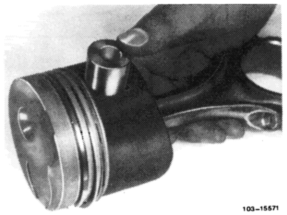
Do not warm up piston.
5 Smear piston pin with engine oil and force into position by hand.
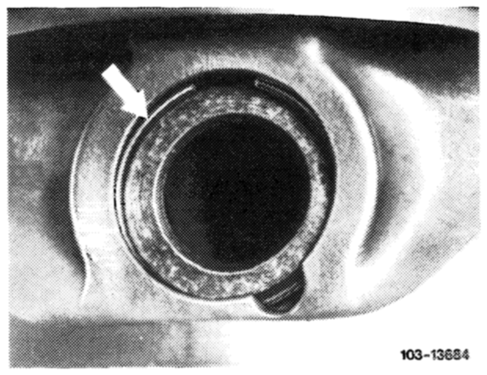
6 Fit piston pin retainer in groove.
Check piston rings for ease of movement.
If fitting used pistons, check piston rings for end and side clearance.
7 Oil cleaned cylinder bores, crankpins, big-end shell bearings and pistons.
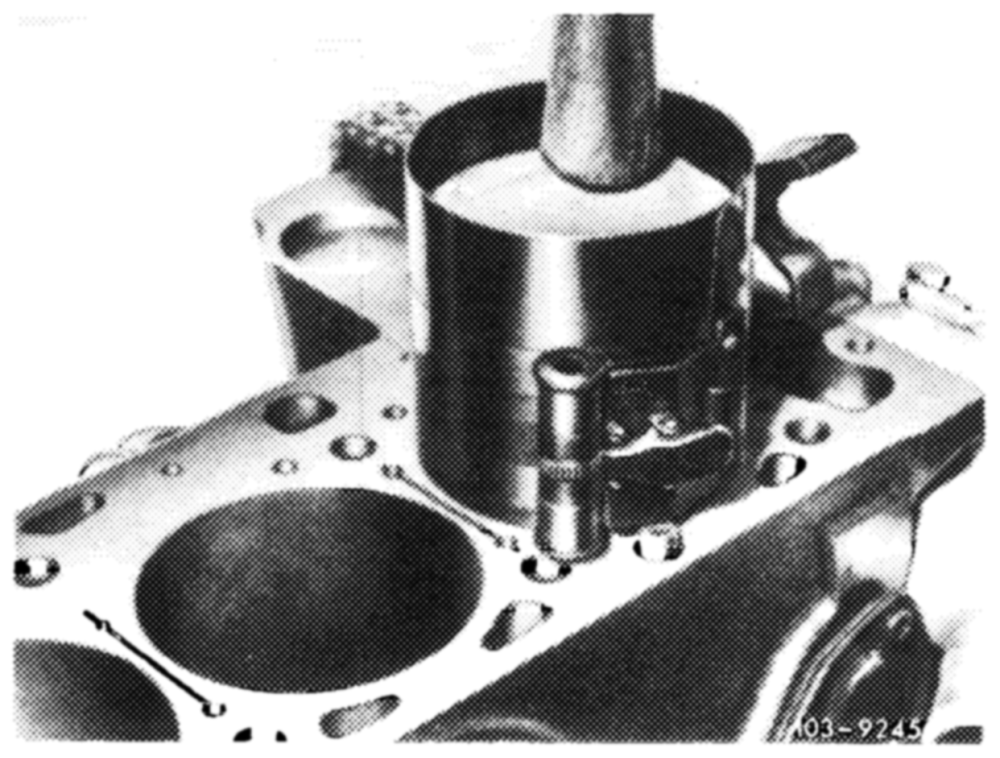
8 Distribute piston ring gaps evenly around piston.
9 Apply piston ring compressor and insert piston.
Arrow in piston crown must point straight-ahead.
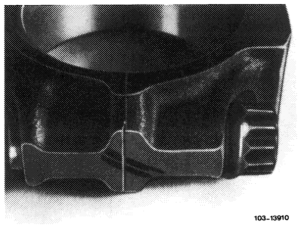
10 Position bearing cap on connecting rod (with code Nos. pointing toward one another), tighten clamp nuts to 40—50 Nm (4—5 kpm) initial torque and then secure by 90—100°.
11. Turn crankshaft and check clearance between piston pin boss and connecting rod.
12 With piston at TDC, measure gap between piston crown and crankcase parting surface (see table).
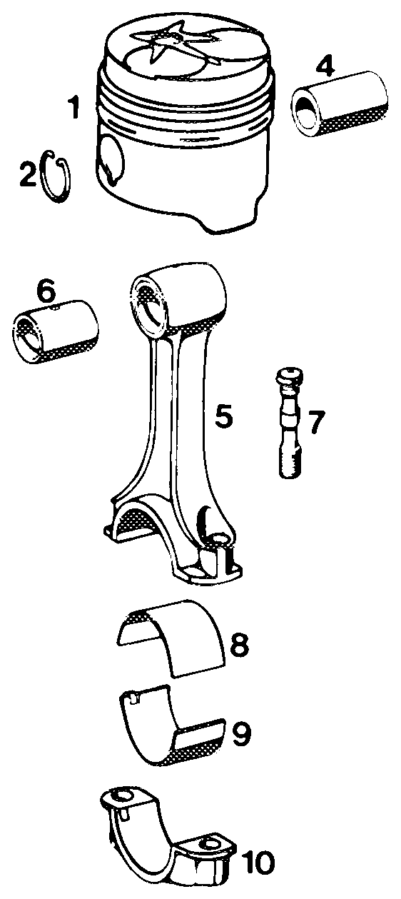
Piston and connecting rod Cs 3a)
1 Piston
2 2 Piston pin snap rings 3a Straight-face ring 3 mm 3b Straight-face ring 2 mm 3c Slotted oi!-contro! ring with spring expander
4 Piston pin
5 Connecting rod
6 Small-end bushing 7 2 clamp bolts 8 _ Big-end bearing, top and bottom halves
10 Bearing cap 11 2 clamp nuts 1 10337786/2