Removing and installing expansion reservoir
WIS 20-4500
Operation no. of operation texts and work units or standard texts and flat rates
A. 24
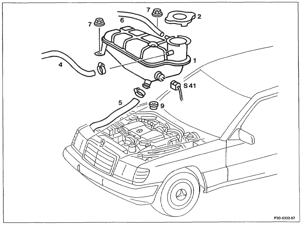
Cap (2) on expansion reservoir (1) ……….. open (release pressure).
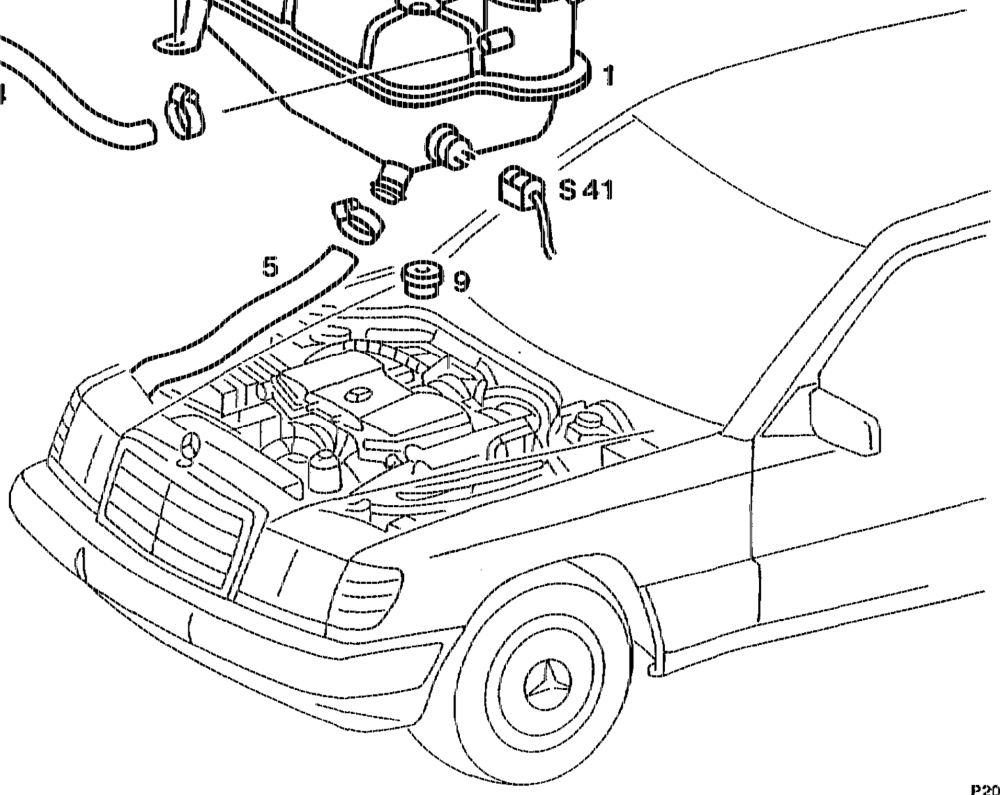
A Do not open cap (2) unless coolant temperature s below 90 °C. Risk of scalding! Coolant 2.2… 2 ee eee teeeeoeees.s drain (until expansion reservoir is empty), pour in (20-0100). Connector of plug connection (S41) of coolant level indicator 2.0.2… .68 208 unplug, plug in.
athe RA 20.1322-4500/1
Coolant hoses (4), (5) 2… eee ee ee detach, attach. Line (6) to overflow reservoir ……….0 0006 detach, attach. Nuts (7) 22. ec ee eee ee ee ee unscrew, Screw on. Expansion reservoir (1) 2.0… 2.2.20. eee remove, install.
Ls Pay attention to rubber pad (9) of expansion reservoir (1).
Note As of vehicle ident end no. 124.034 1B 786 454 and 124.036 1B 783 119, respectively, an expansion reservoir 124 500 15 49 with integrated vent valve has been installed. This prevents air getting into the cooling circuit when the coolant level drops.
Detach coolant hose (4) for filling.
othe § RA 20.1322-4500/2
B. Model 129
Operation no. of operation texts and work units or standard texts and flat rates
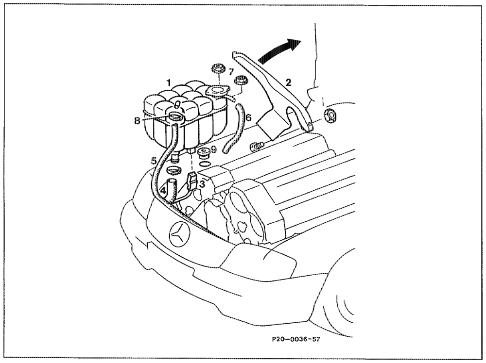
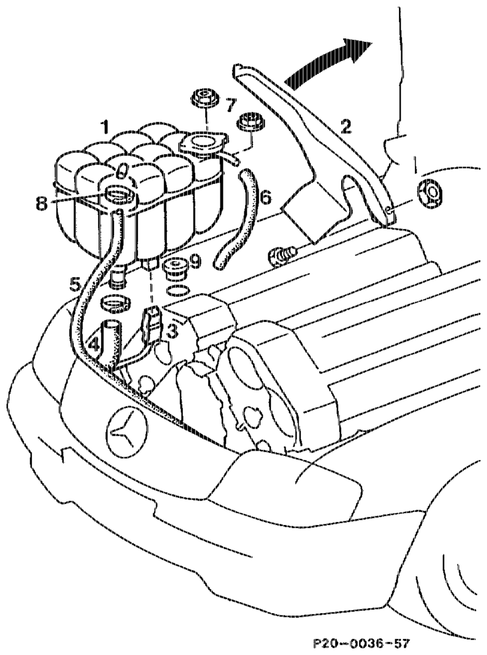
Cap of expansion tank (1) ……….666 see open (release pressure), Goolant . 2… eee ee eee drain (until expansion reservoir is ernpty), pour in (20-0100). Over (2)… eee sete eee twee nae unbolt, lift off, install. Connector (3) of coolant level indicator switch … unplug, plug in. Coolant hoses (4), (5), (6)… 2… ee eee ee eee detach, attach. Nuts (7) …… see eee cee teen eee . unscrew, screw on. Expansion reservoir (1)… ….0…000 0000 remove, install.
A Pay attention to rubber pad (9) of expansion reservoir (1).
nite RA 20,1322-4500/3
Note As of vehicle ident end no. 001 950 an expansion tank with the identification 129 500 03 49 (was 129 500 01 49) has been installed. Identification on top side of reservoir. This reservoir has a modified vent connection to ensure improved ventilation of the systern. When performing repairs, install this reservoir.
As of vehicle ident end no. 022 927 an expansion reservoir with a ventilation line to the heating systern has been installed.
whbia RA 20.1322-4500/4
C. Model 140
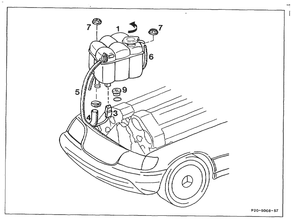
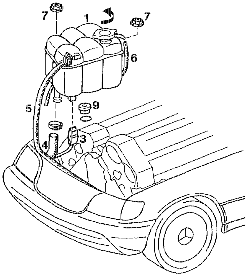
Operation no. of operation texts and work units or standard texts and flat rates
Cap of expansion reservoir (1) oe open (release pressure). Coolant 2.0… eee eee drain (until expansion reservoir is ernpty), pour in (20-0100). Connector (3) of coolant level indicator switch unplug, plug in. Coolant hoses (4), (5), (6) sees detach, attach. Nuts (7) vee eee vee ee eee unscrew, screw on. Expansion reservoir (1) remove, install.
AN Pay attention to rubber pad (9) of expansion reservoir (1).
whhie RA 20.1322-4500/5