Test program (model year 1975)
WIS 14-100
Federal and California version model year 1975/76
For complaints such as: Poor warming-up characteristics of engine, poor idle speed, engine not accelerating or splashing during acceleration, check emission control system for function.
Test conditions: All fuses in order, engine at operating temperature, run engine at idle speed.
Test the following: EGR, air injection, starter cover-stepped heater and fuel evaporation system.
Function diagram
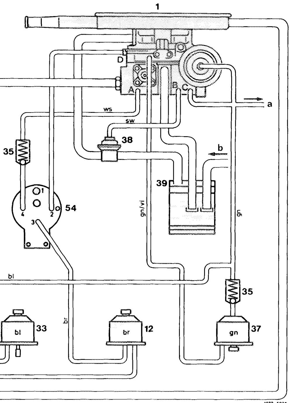
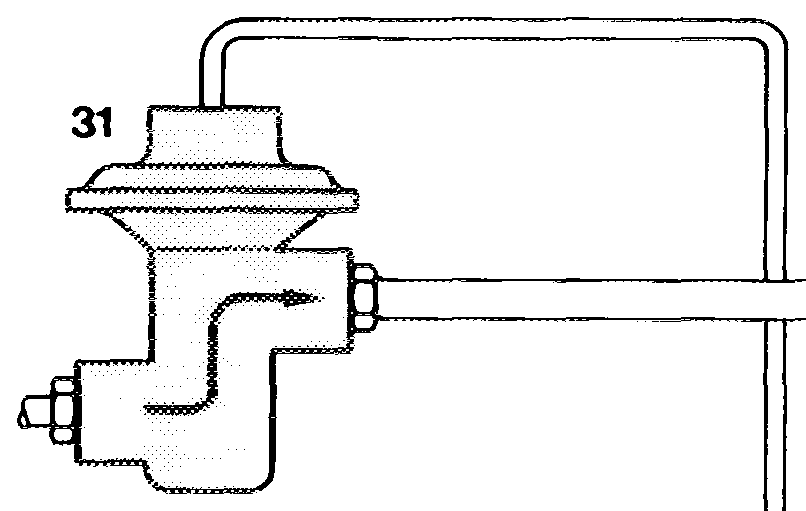
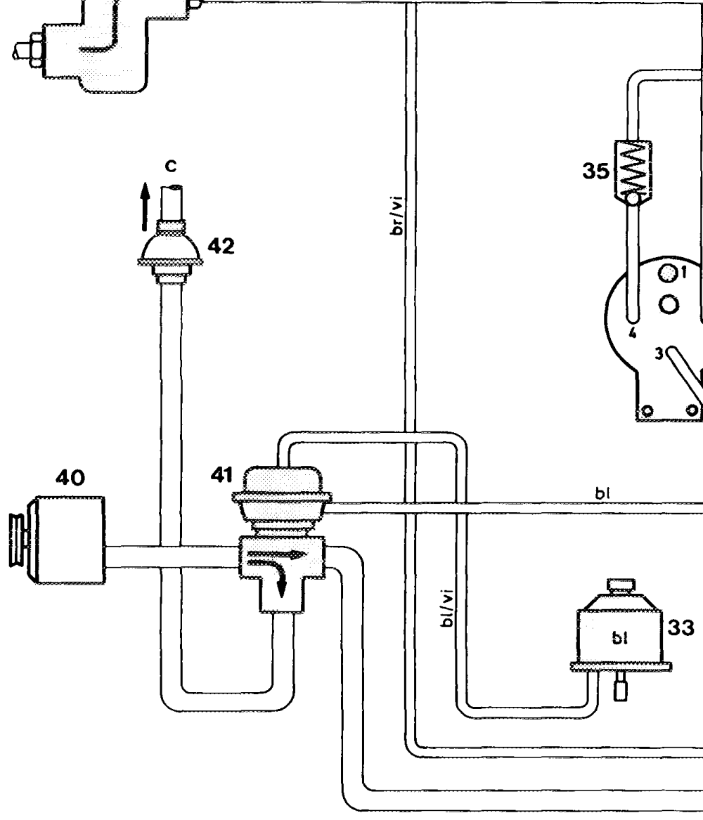
1 Carburetor 40 Air pump bl = blue
12 Switch-over valve EGR 41 Anti-backfire valve br = brown
31 EGR valve 42 Check valve air injection gn = green
33 Switch-over valve air injection 54 Vacuum booster sw = black
35 Check valve vi = purple
37 Switch-over valve float chamber vent Connection fuel check valve ws = white a
38 Purge valve b = Connection tank vent
39 Charcoal canister c_ Air injection
14.2-100/1 USA 1975/76 F2
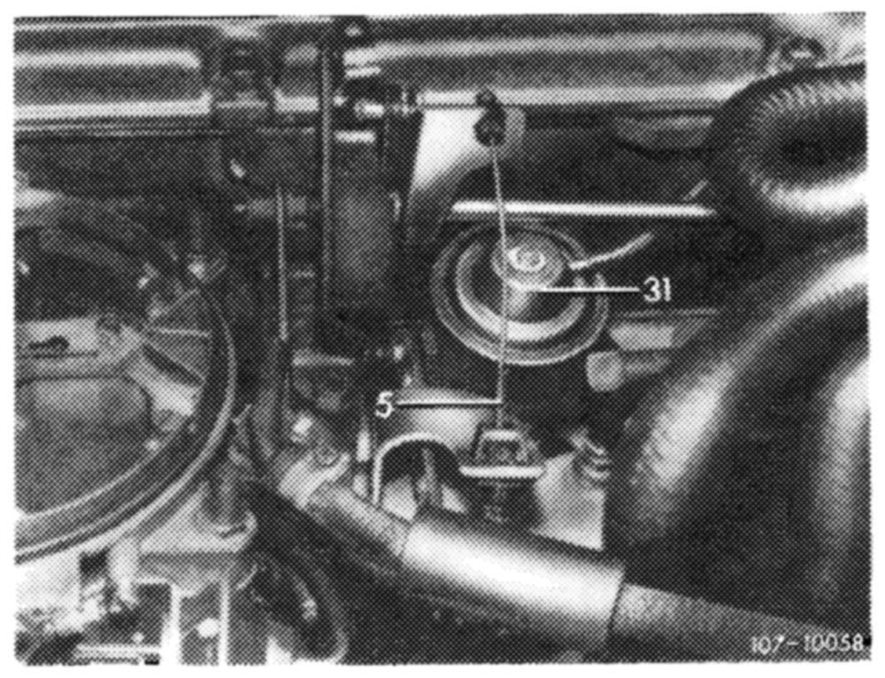
Testing EGR
Selector lever in position ‘‘N’’ or ““P’’.
Pull-off brown/purple vacuum line on EGR valve (31), blow out line.
Passage in No passage. order.
ne
Test vacuum lines
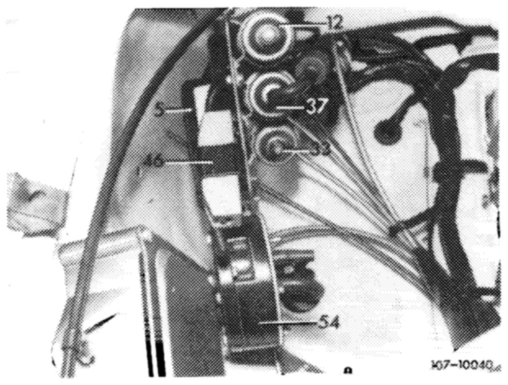
The brown vacuum line of vacuum booster (connection 3) should be plugged on center connection of brown switch-over valve (12), the brown/purple vacuum line to EGR valve should be plugged to outer connection of switch-over valve.
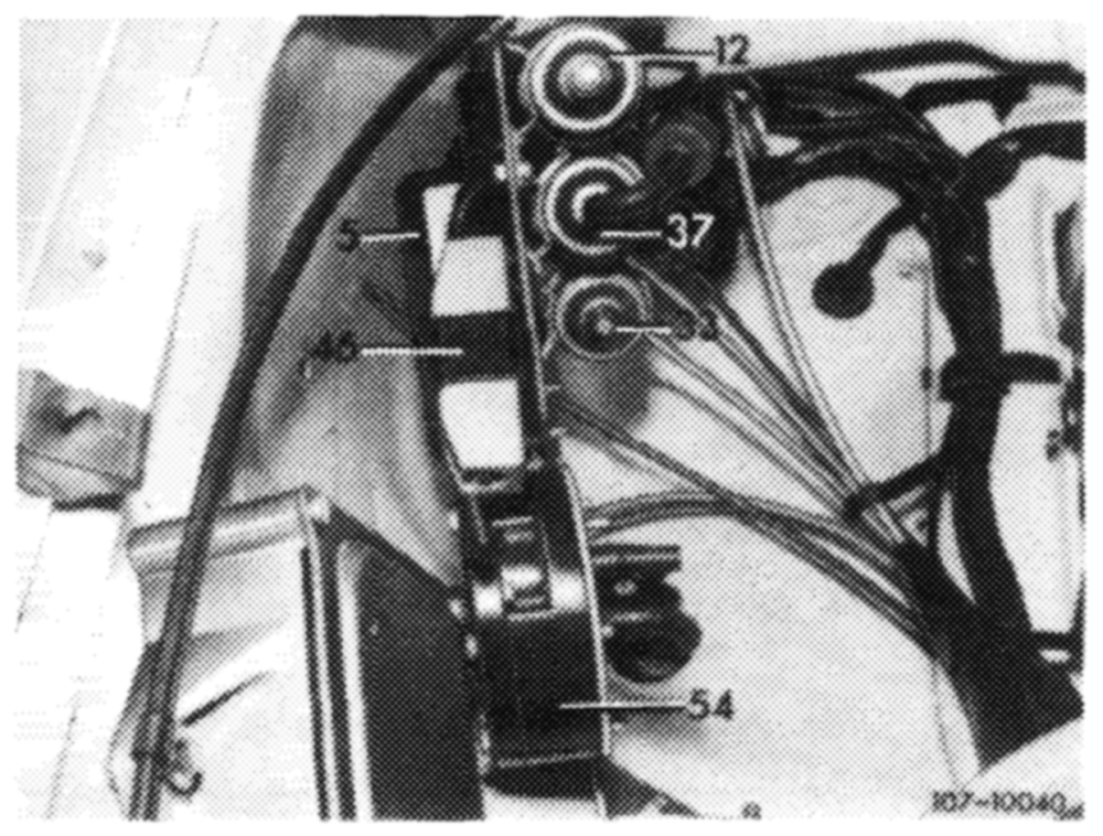
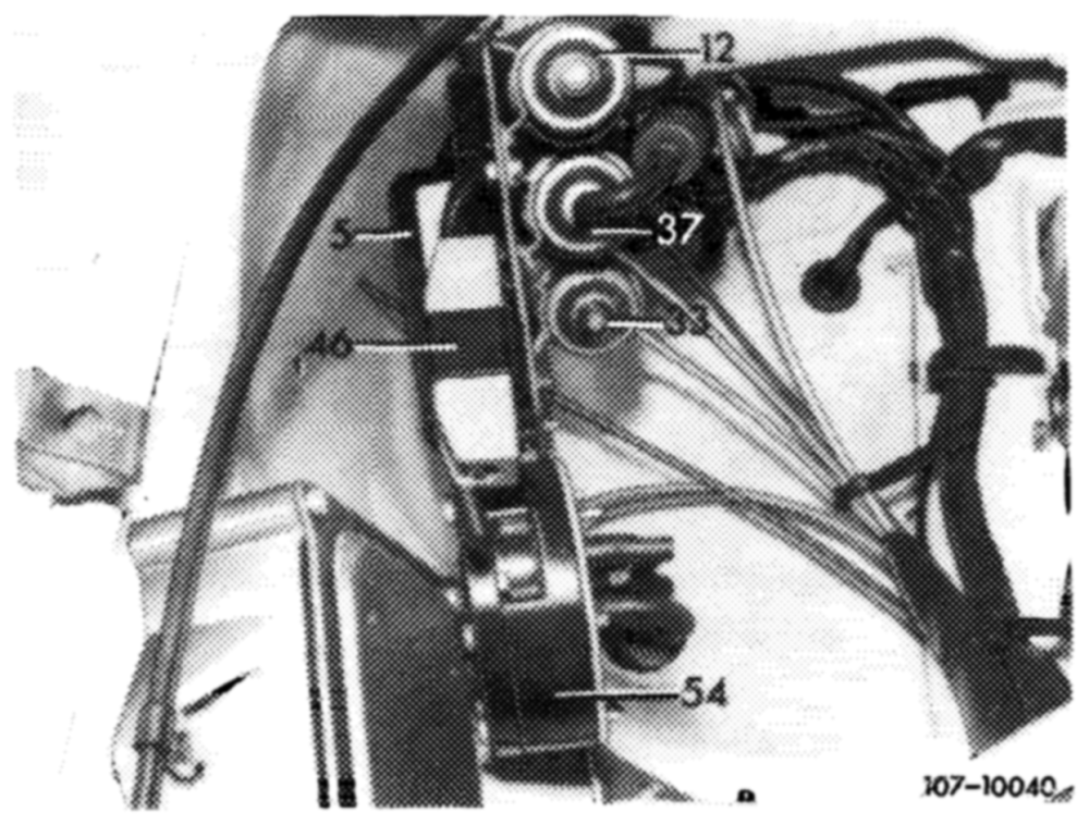
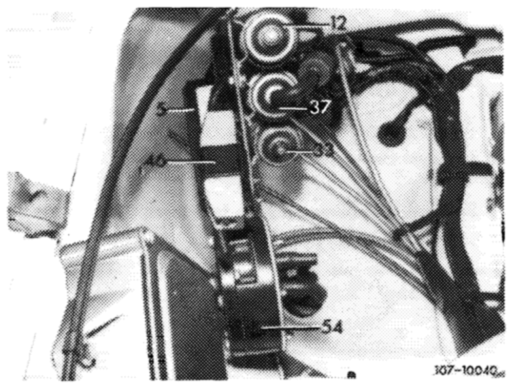
Test relay box (5)
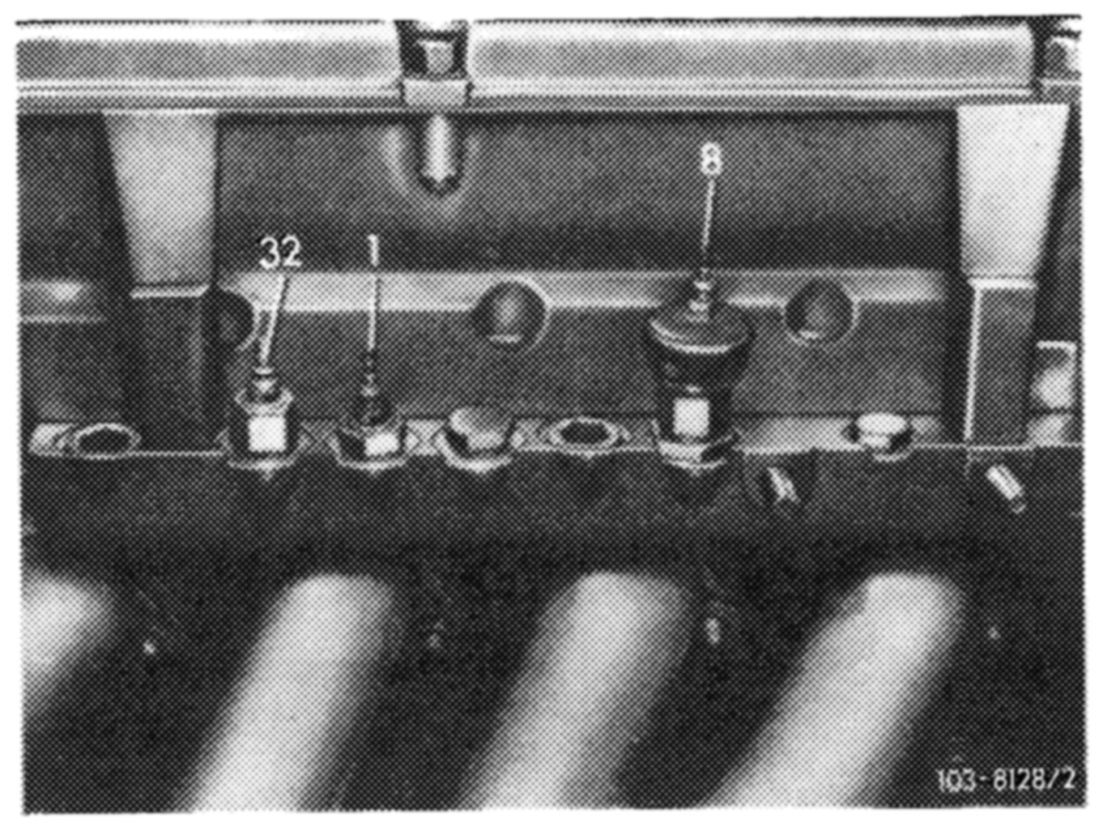
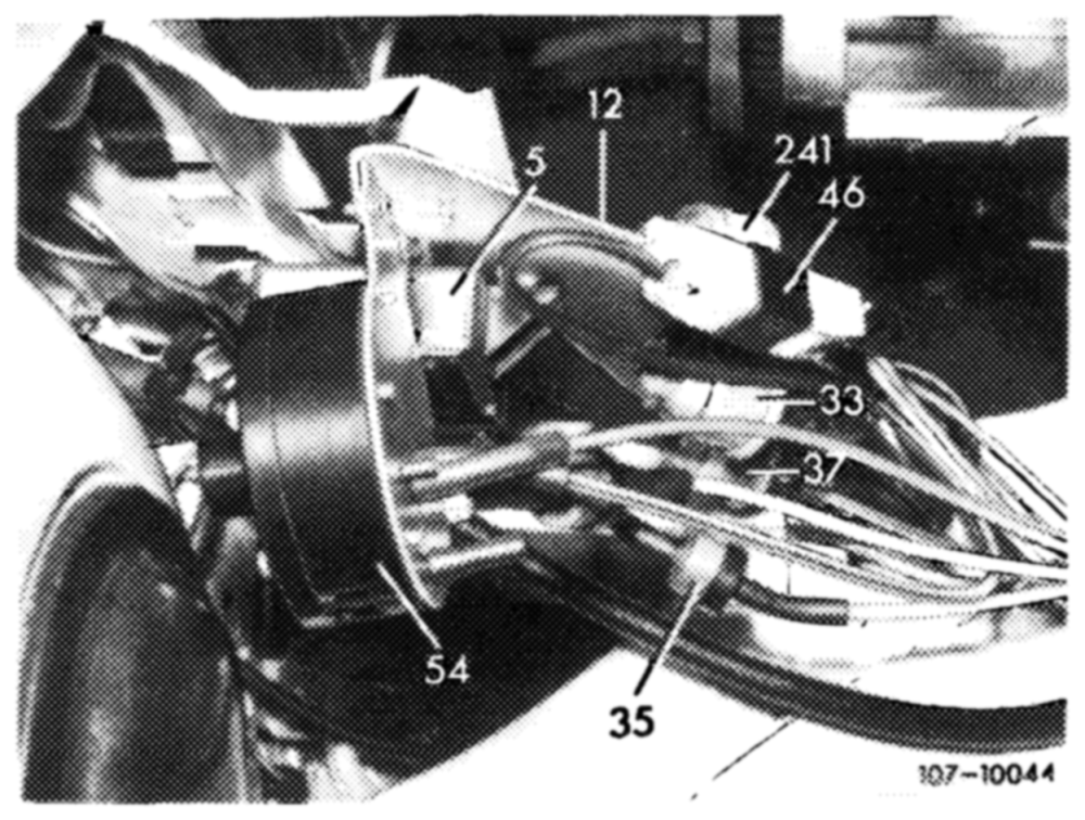
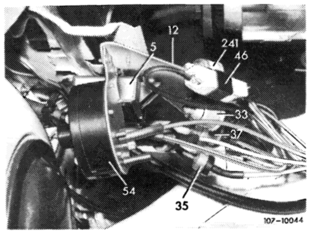
Pull coupler from switch-over valve (12), connect voltmeter to coupler. Pull plug from temperature switch (32) and connect to ground. With the ignition switched on, voltmeter should indicate approx. 13 Volts. If no voltage is indicated, renew relay box (5).
Testing switch-over valve (12)
Pull coupler from relay box (5). Connect terminal 3 and 4 with test cable.
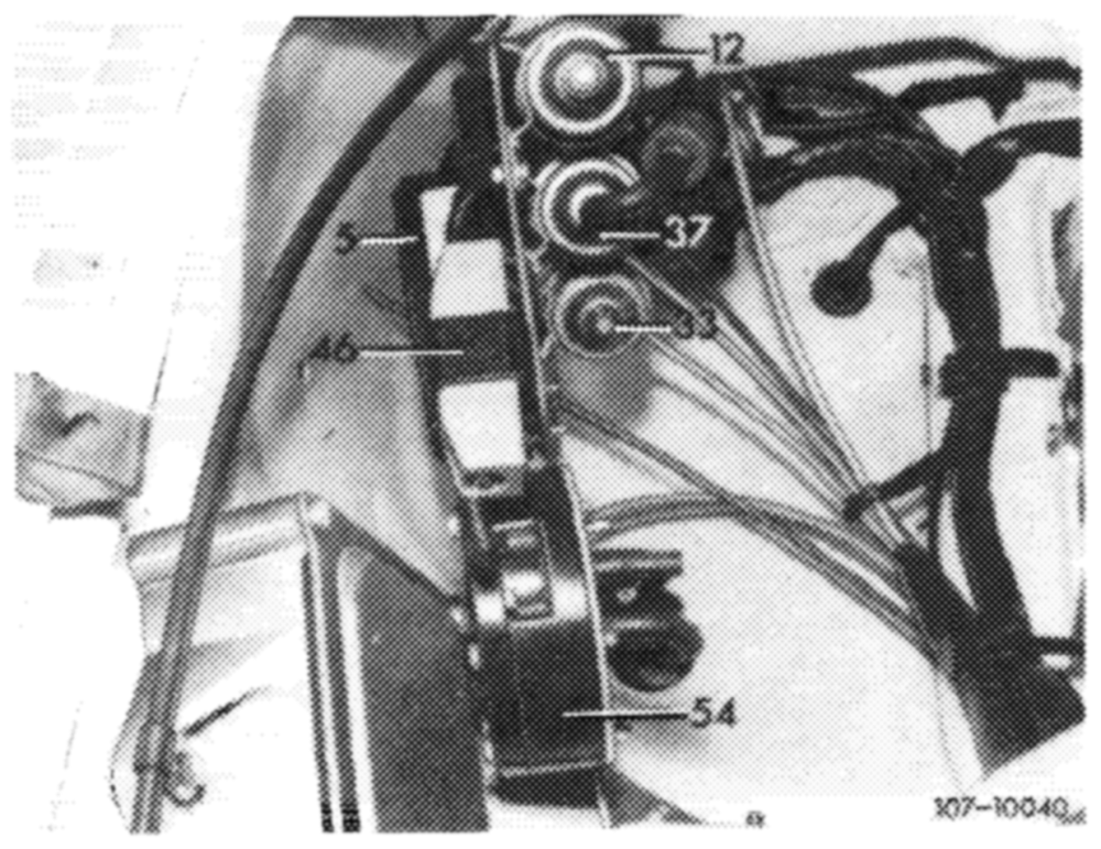
Switch on ignition. Switch-over valve (12) should audibly or noticeably switch.
=P
14.2-100/2 USA 1975/76 F2
Test starter lockout and back-up lamp switch
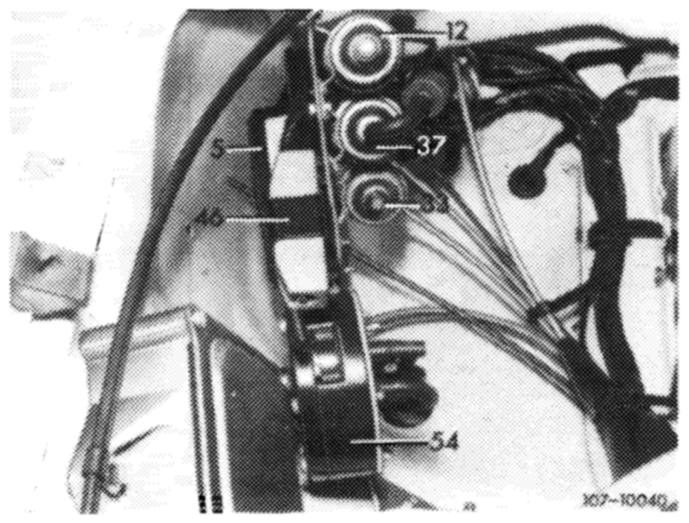
Pull coupler from relay box (5) and connect voltmeter to terminal 2 and 5. Switch on ignition. In selector lever position ‘‘N” or “P” the voltmeter should indicate approx. 12 Volts.
If voltmeter indicates voltage, replace relay box (5).
If voltmeter indicates no voltage, renew starter lockout and back-up lamp switch.
PO
Testing EGR
Selector lever in driving position (step down on pedal of parking brake).
Pull brown/purple vacuum line from EGR valve (31), blow through line.
No passage. Passage in order.
Test starter lockout and back-up lamp switch
Pull coupler from relay box (5) and connect voltmeter to terminal 2 and 5. Switch on ignition. In a driving position, voltmeter should indicate 0 Volt.
=e
14,2–100/3_ USA 1975/76 F2
If voltmeter indicates 0 Volt, renew relay box (5).
If voltmeter indicates voltage, renew starter lockout and back-up lamp switch.
| “FF __ | “F | |
| Testing EGR Selector lever in position ‘‘N” or ‘“’P’’. Pull-off brown line on carburetor, connection “‘D” and green line on carburetor. Plug-on brown tine instead of green line. | ee | |
| Engine speed remains the same. | Engine speed drops, engine stops. | |
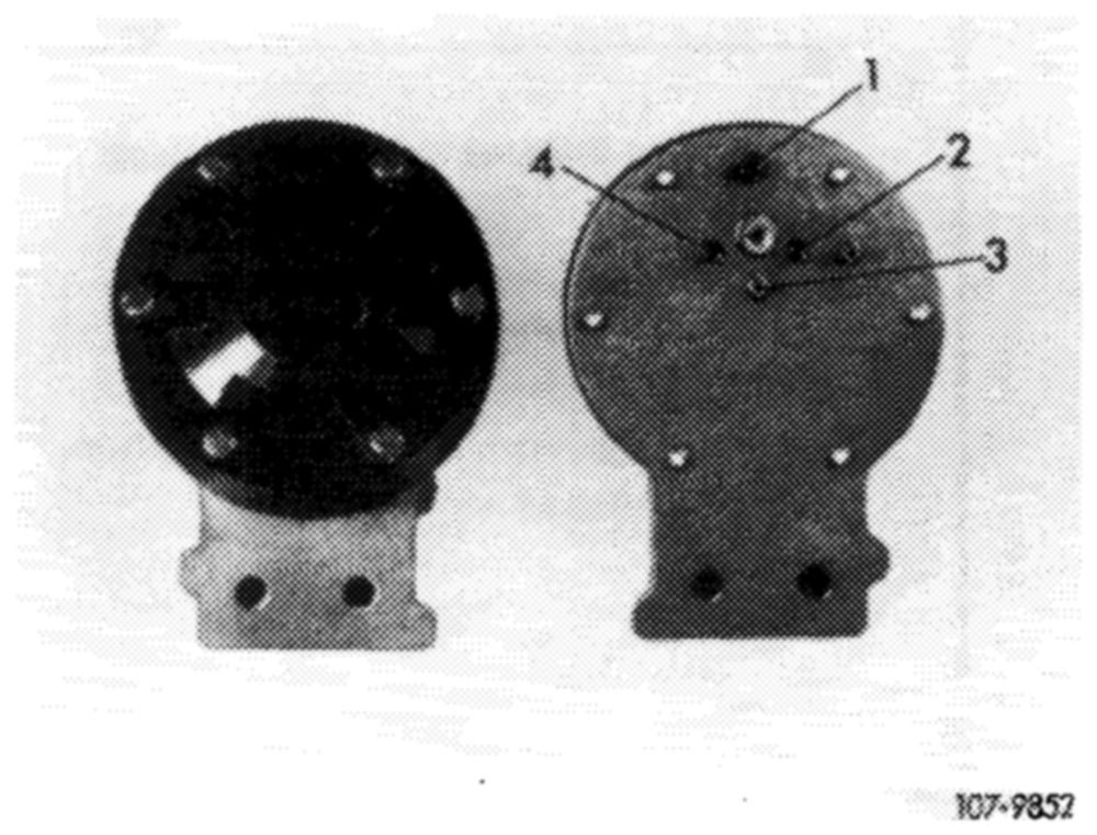
Test vacuum lines on vacuum booster (54)
Connection closed by rubber cap PWN Connection Venturi vacuum Connection switch-over valve EGR Connection intake manifold vacuum (carburetor connection A)
Unused connections are for venting.
ee er
14.2-100/4 USA 1975/76 F2
Testing EGR
Selector lever in driving position (step down on pedal of parking brake).
Pull-off brown line on carburetor, connection “’D” and green line on carburetor. Plug-on brown line instead of green line.
| speed drops, | Engine speed remains |
| stops. | the same. |
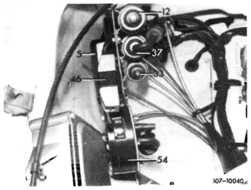
Test connection for Venturi vacuum for passage
Test EGR valve (31)
Pull-off brown/purple line on brown switch-over valve (12), start engine. Pulloff green line on green switch-over valve (37). Connect brown/purple line to green line. Engine should run irregularly or stop.
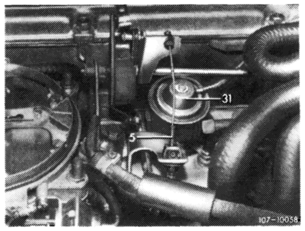
If engine speed is not changing, renew EGR valve (31).
If engine speed changes, renew vacuum booster (54).
Testing air injection
Pull-off connecting hose of air injection on air filter (center hose).
Connecting hose remains pulled-off for next test.
Air flowing out. No air flowing out.
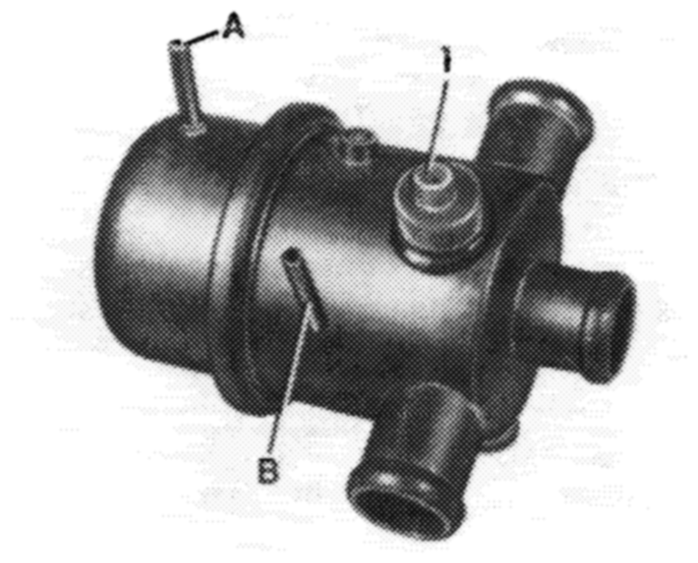
Pull-off hose of air discharge line on air filter. If an air flow shows up:
Test vacuum lines
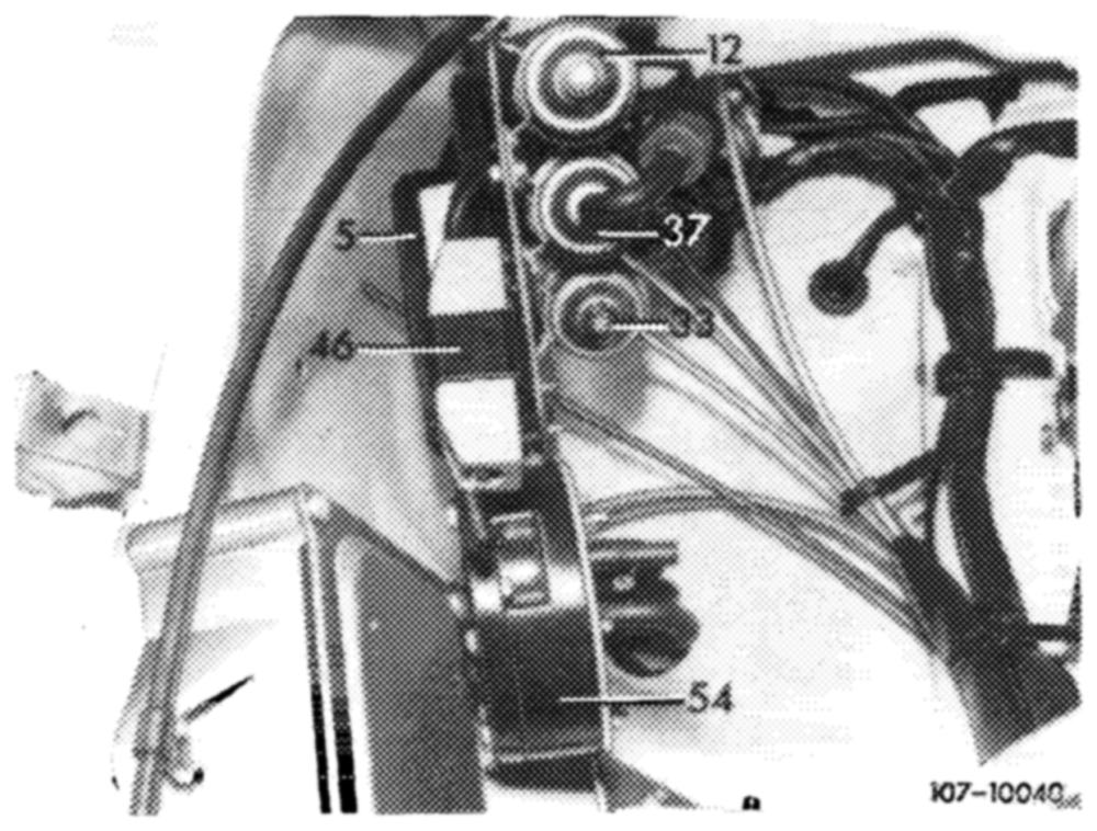
The blue vacuum line should be connected to connection ‘’B” of anti-backfire valve (41), the blue/purple line to connection “A”.
Test switch-over valve (33)
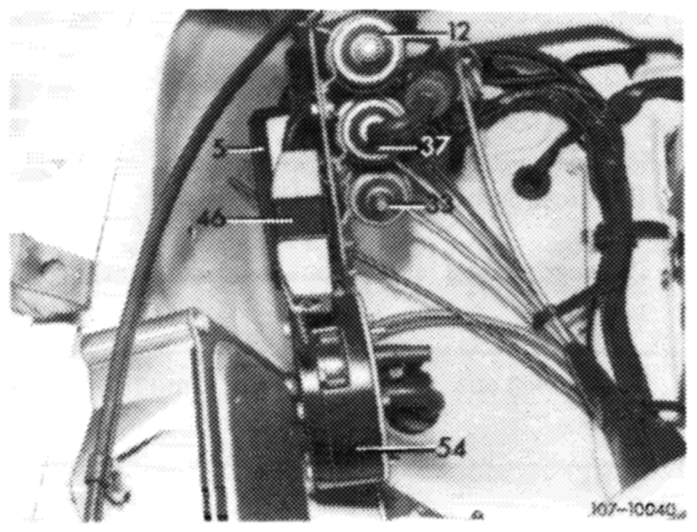
Pull-off coupler on relay box (5), connect terminal 2 and 9 with test cable. With ignition switched on, the blue switch-over valve should audibly or noticeably switch.
If in spite of perfect function of these components air is discharged at idle, renew anti-backfire valve.
Testing air injection
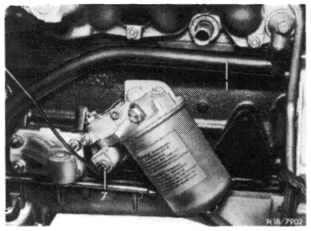
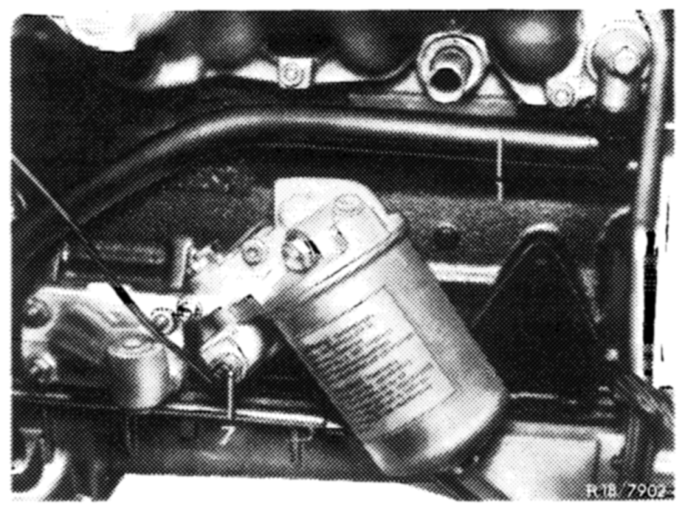
Separate plug connection of electric line to temperature switch 17 °C (7) in oil filter housing and connect to ground.
Air injection is Air injection is interrupted. not interrupted.
Test relay box (5)
Pull coupling from blue switch-over valve (33). Connect voltmeter. Separate plug connection of electric line to temperature switch (7) and connect with test cable to ground. Switch on ignition. Voltmeter should indicate approx. 12 Volts.
If no voltage is indicated, renew relay box (5).
Testing choke cover-stepped heater
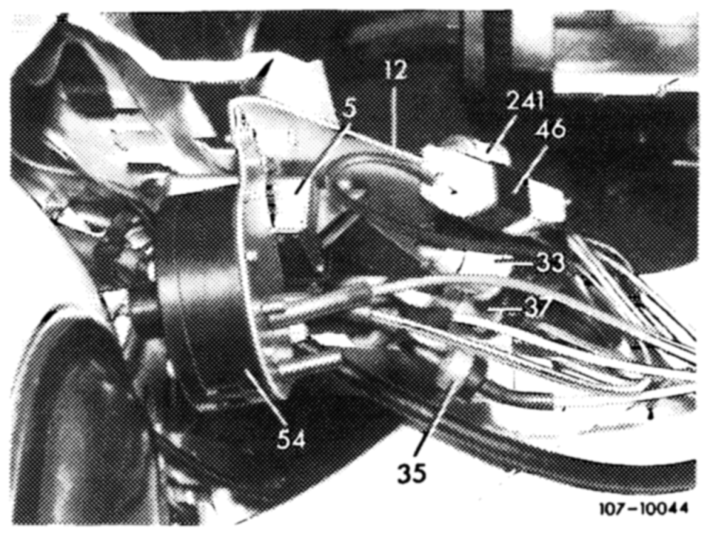
Connect voltmeter to output of resistance (46) and to ground. Separate plug connection of electric line to temperature switch 17 °C (7) and connect to ground.
Voltmeter indicates Voltmeter does not 7–8 Volts. indicate 7–8 Volts.
i ofl
Testing relay box (5)
Connect voltmeter to input of resistance (46) and to ground.
Connect plug connection of temperature switch to ground. Voltmeter should indicate 7–8 Volts.
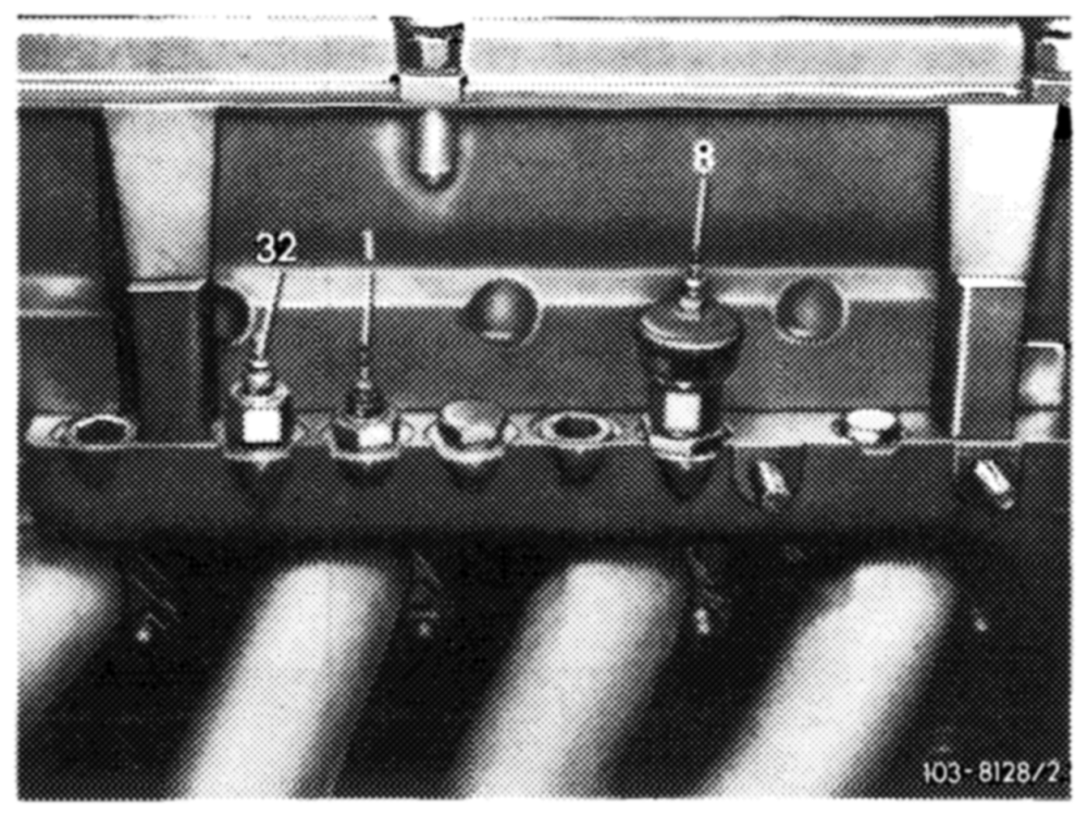
If no voltage is indicated, renew relay box (5).
Testing choke cover-stepped heater
Connect voltmeter to output of resistance (46) and to ground.
Pull plug from temperature switch 65 °C.
Voltmeter indicates Voltmeter does not approx. 12 Volts. indicate approx. 12 Volts.
Pr Renew relay box (5).
=” =e
14.2-100/7, USA 1975/76 F2
Testing fuel evaporation system
Install vacuum pressure gauge into green/purple vacuum line to float chamber vent valve. Accelerate engine for a short moment.
Vacuum available, No vacuum, remains constant. vacuum drops.
F
Test vacuum lines
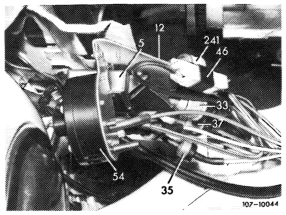
The green vacuum line of carburetor should be plugged at top to switch-over valve (37), the green/purple vacuum line to float chamber vent valve at bottom to switch-over valve (37).
Test switch-over valve (37)
Pull coupler from switch-over valve (37) and connect voltmeter. With the ignition switched on, voltmeter should indicate approx. 12 Volts.
\f coupler is connected to voltage, slip coupler on valve. Switch-over valve should audibly or noticeably switch.
If vacuum is not remaining constant:
Test float chamber vent valve for leaks
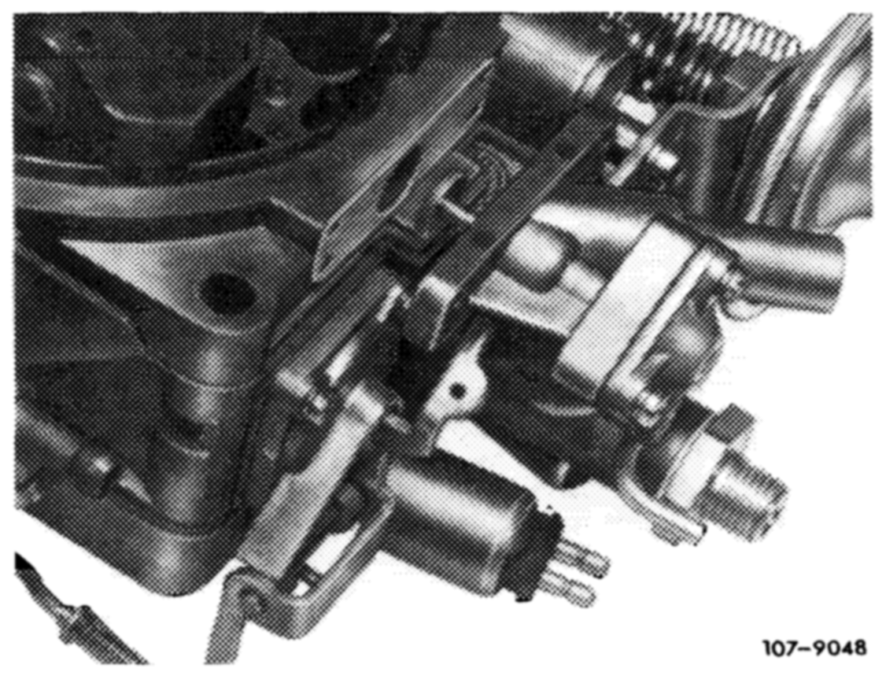
Unscrew float chamber vent valve. With vacuum line connected, run engine at idle, keep vent bore on carburetor closed, if required, piston rod of valve should then move. Renew vacuum diaphragms of valve, if required.
TF =F
14,.2-100/8 USA 1975/76 F2
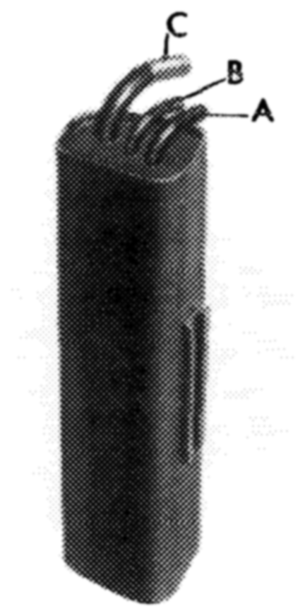
Testing vacuum evaporation control system
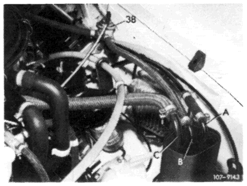
Pull center (thin) hose from charcoal canister and keep hose opening closed with finger. Increase engine speed slowly above approx. 2000/min.
Vacuum available, No vacuum. vacuum increases with increasing speed.
=
Test draw-off line to intake pipe
For this purpose, loosen hose to charcoal canister on purge valve (38) and blow out valve in direction of intake pipe by means of compressed air. Renew purge valve (38), if required.
If vacuum is not increasing at increasing speed:
Test vacuum at purge vaive (38)
Pull-off black vacuum line on purge valve (38). Connect vacuum pressure gauge or keep hose opening closed with finger. Slowly accelerate engine speed. No vacuum should be available at idle. At increasing speed, a vacuum should be established.
If vacuum is available, renew purge valve (38).
If no vacuum is available, blow out vacuum line to carburetor with compressed air.
End of test
14.2-100/9 USA 1975/76 F2