Test program (model year 1973)
WIS 14-100
Federal version model year 1973/74 California version model year 1973
For complaints such as: Poor warming-up characteristics of engine, poor idle speed, engine not accelerating or splashing during acceleration, check emission control system for function.
Test conditions: All fuses in order, engine at operating temperature, run engine at idle speed.
Test the following: Ignition switch-over, EGR and choke cover-stepped heater.
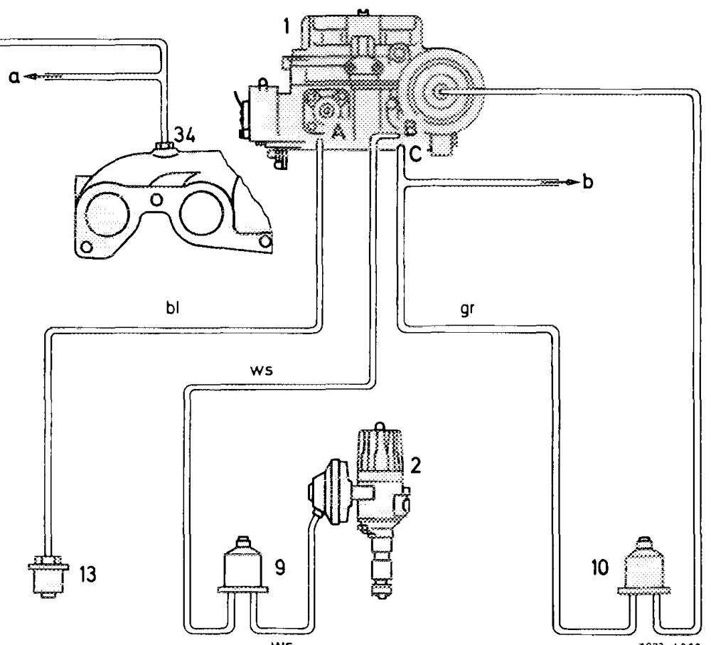
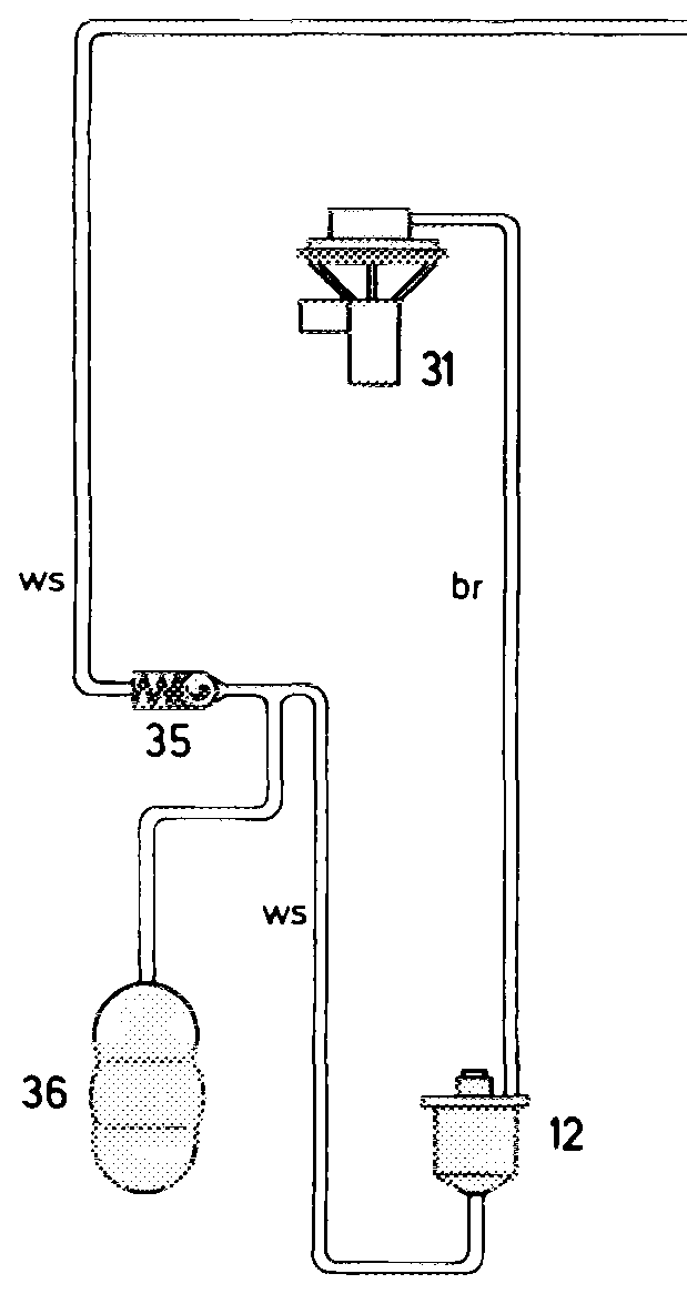
Function diagram
ws 7073-4669
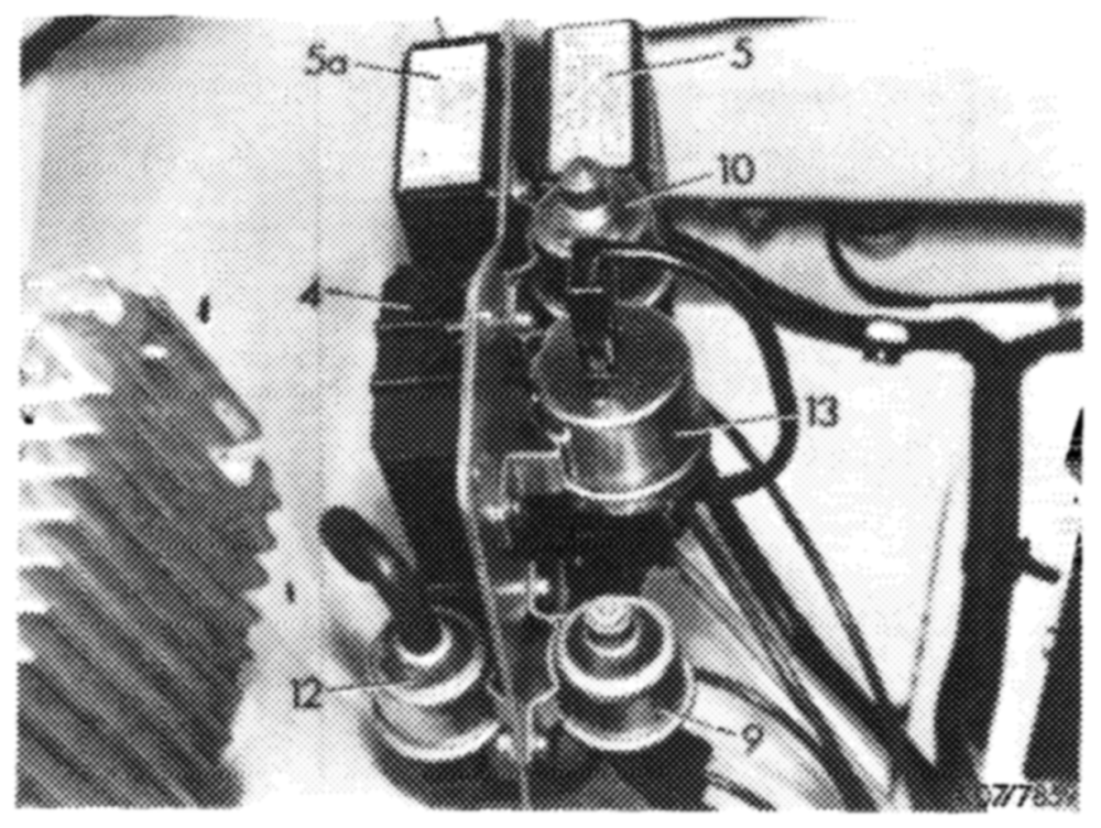
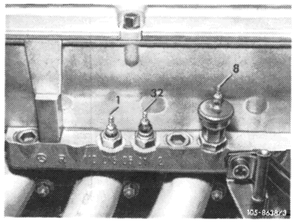
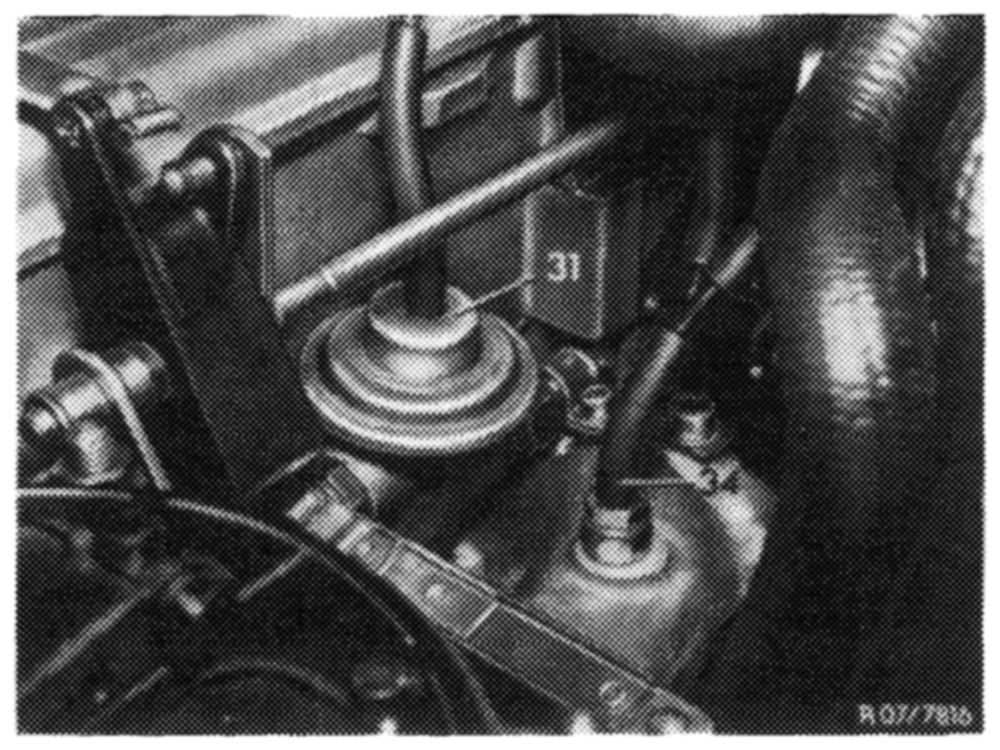
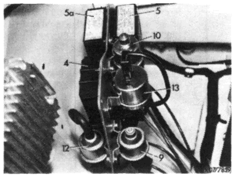
9 Switch-over valve ignition 34 Vacuum connection to intake pipe bl = blue 10 Switch-over valve throttle valve lift 35 Check valve br = brown 12 Switch-over valve EGR 36 Vacuum tank gr = grey 13 Vacuum switch a Vacuum connection air conditioner ws = white 31 EGR valve b Vacuum connection fuel return valve
14,2–100/1 USA 1973/74 F2
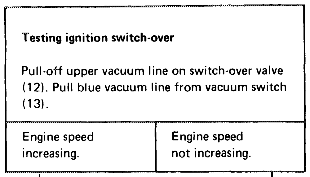
Testing ignition switch-over
| plug connection of electric line to | yn of electric line to 0 EES EEE |
| switch 17 °C | in oil filter |
| connect to ground. | (7) housing |
| speed | Engine speed not increasing. |
Check vacuum lines
Check white vacuum lines from carburetor to switch-over valve (9) and from switchover valve to ignition distributor for condition and correct connection.
The vacuum originating line from carburetor must be plugged to center connection of switch-over valve.
Check switch-over valve (9)
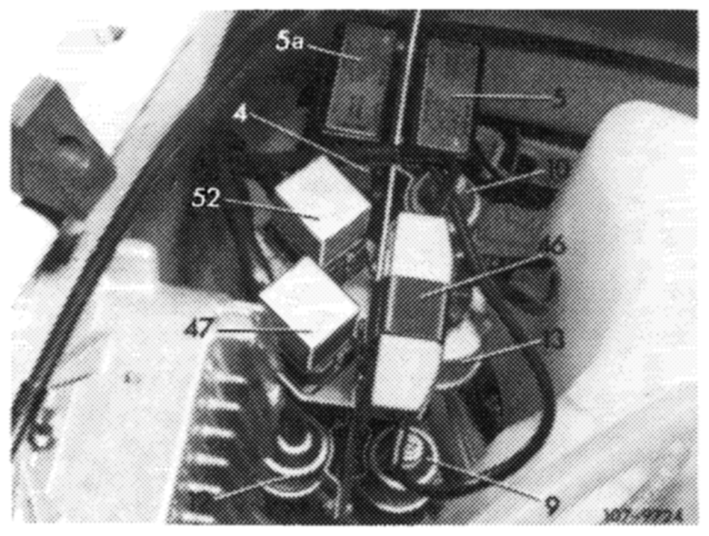
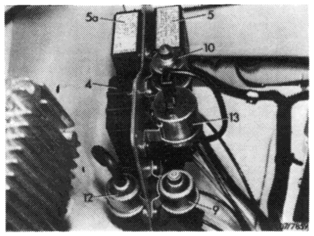
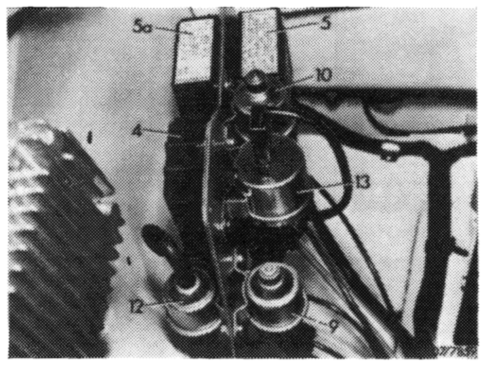
Pull couplers from relay boxes (5 and 5a) On coupler of relay box (5a) connect terminals 8 and 9. With ignition switched on, the switch-over valve (9) should switch both audibly and noticeably.
Check relay of temperature switch 17 °C (52) (Only on vehicles with choke cover-stepped heater [front relay short cable]).
Pull coupler from relay for resistance of choke cover (47) and connect voltmeter to terminal 5 and 3. With ignition switched on, the voltmeter should indicate approx.
13 Volts. Release plug connection of electric line to temperature switch 17 °C and connect to ground. Voltmeter should indicate 0 Volt.
If no voltage is measured, renew relay for temperature switch 17 °C (52).
w w
14.2-100/2, USA 1973/74 F2
Testing ignition switch-over
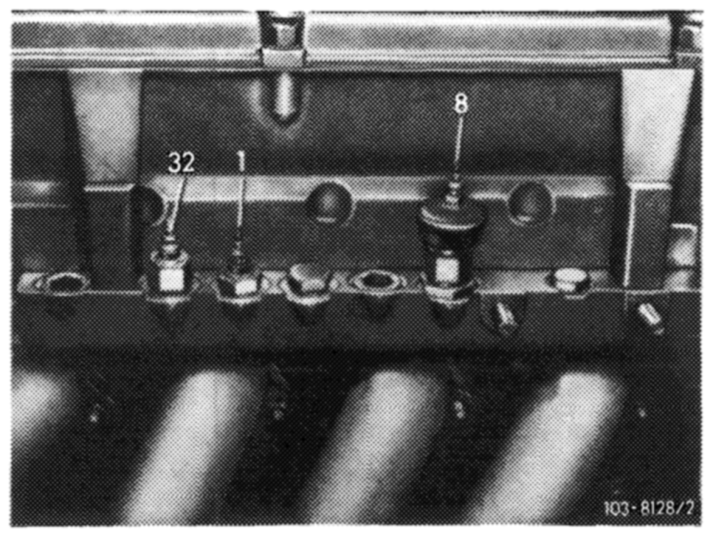
Pull plug from temperature switch 100 °c (8) and connect to ground.
Engine speed Engine speed increasing. not increasing.
“ar
Check cable connection
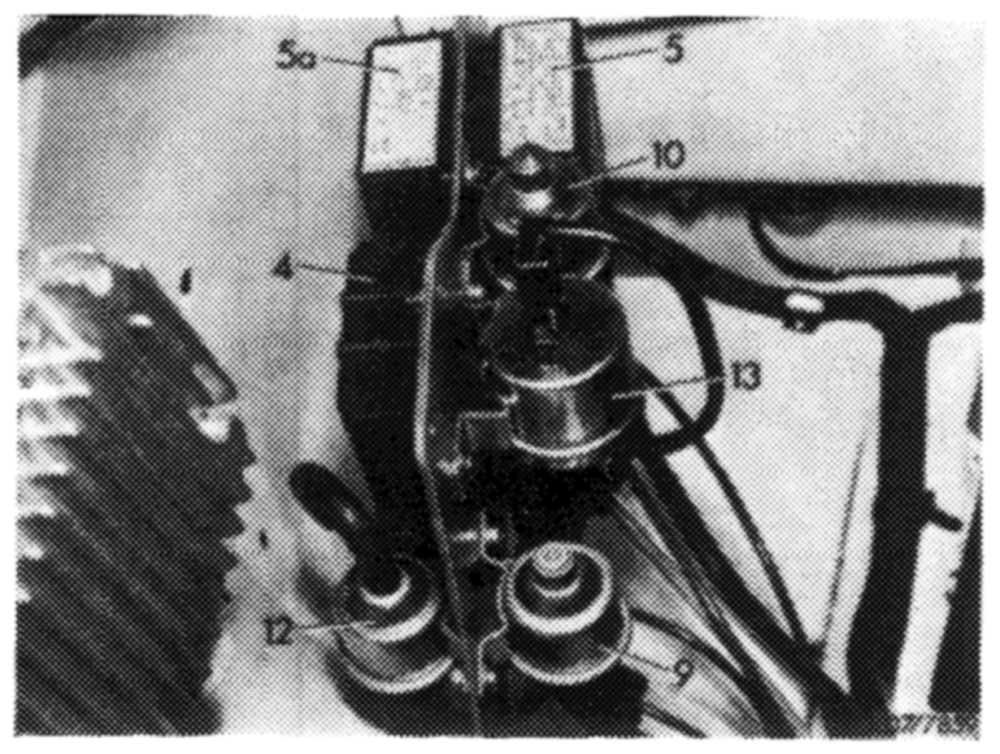
Pull plug from temperature switch (8) and connect voltmeter to plug and ground. Pull coupler from relay box (5a), connect terminal 8 and 4. With ignition switched on, the voltmeter should indicate approx. 13 Volts.
If voltmeter indicates approx. 13 Volts, renew relay box (5a).
Testing ignition switch-over
Switch on air conditioner to full capacity.
Engine speed Engine speed remains the same. drops.
all
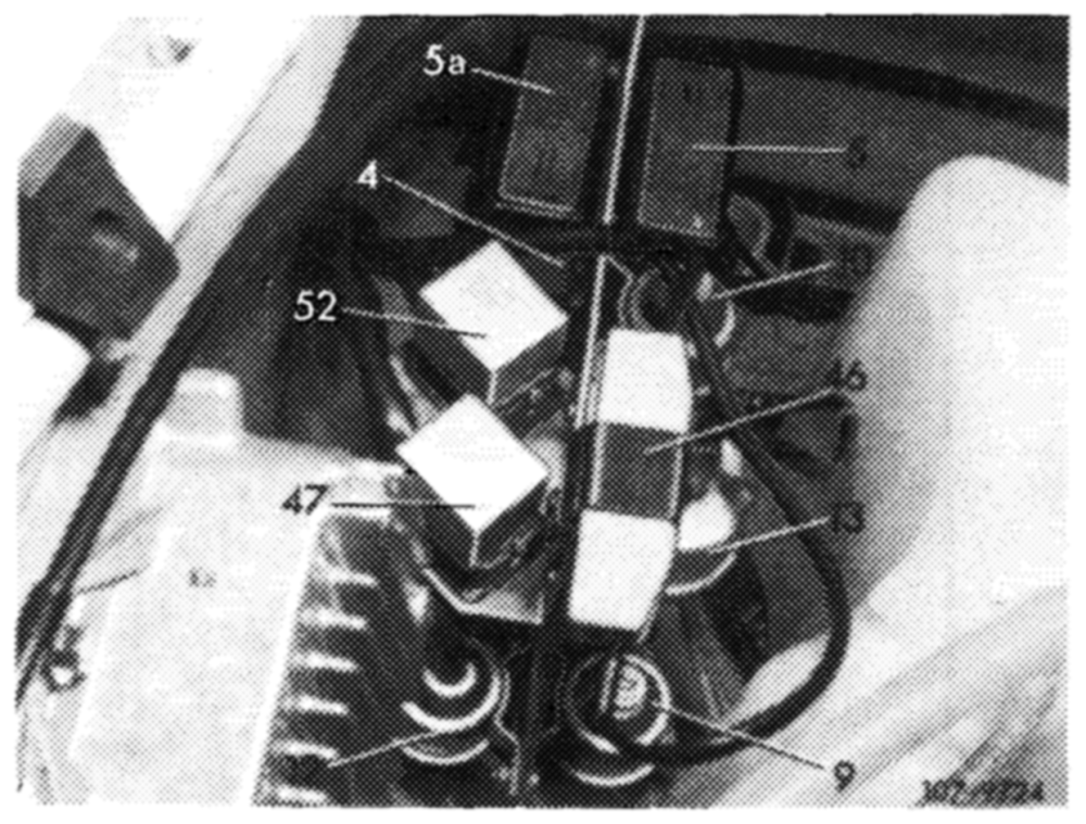
Check voltage Pull coupler from relay box (5). Connect voltmeter to terminal 2 and 3. With air conditioner switched on and engine running, the voltmeter should indicate approx. 13 Volts. If voltmeter indicates approx. 13 Volts, renew relay box (5a). If no voltage is measured, look for fault in cable lines to air conditioner.
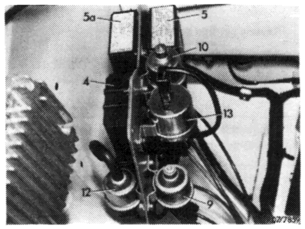
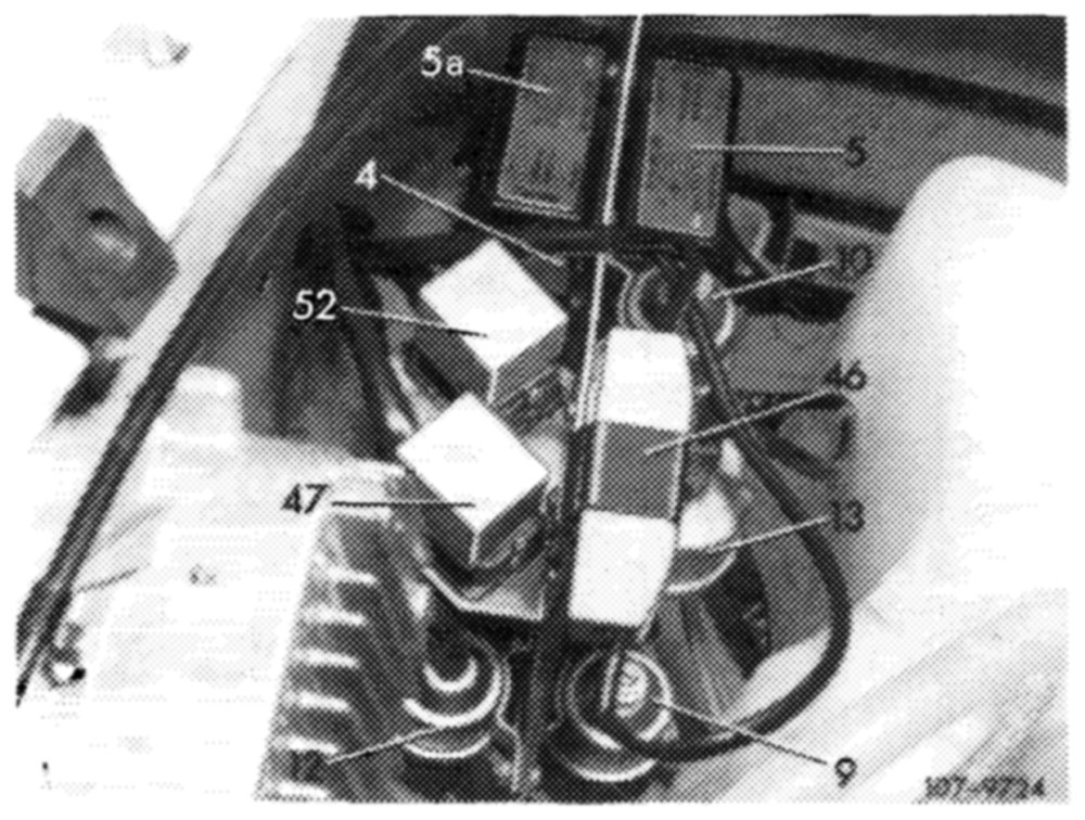
Test vacuum switch (13)
Pull coupler from relay box (5). Connect voltmeter to terminal 7 and 8. Run engine at idle speed, voltmeter should indicate approx. 13 Volts.
Pull-off vacuum line on vacuum switch (13). Voltmeter should indicate 0 Volt.
If voltage is indicated, renew relay box (5).
a
Testing ignition switch-over
Pull coupler from plug connection (49) on relay support and connect plug no. 2 to ground (cable color brown/white).
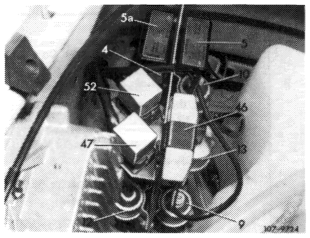
Engine speed Engine speed increasing. not increasing.
—
14,2-100/4 USA 1973/74 F2
Testing EGR
Pull blue vacuum line from vacuum switch (13).
| Engine speed drops, | Engine speed |
| engine stops. | not dropping. |
Test temperature switch 65 °C (32)
Pull coupler from relay box (5) and connect voltmeter to terminal 8 and 6. Above 65 °C coolant temperature, voltmeter should indicate approx. 13 Volts.
Testing switch-over valve (12)
Pull coupler from relay box (5). Connect terminal 8 and 5. With ignition switched on, the switch-over valve (12) should switch audibly and noticeably.
Testing EGR valve (31)
For testing, valve must be directly supplied with vacuum.
Run engine at idle speed. Pull-off both vacuum lines on switch-over valve (12) and connect. Engine should run irregularly and stop.
If tests are showing no faults, renew relay box (5).
ee +
Testing EGR
Pull brown vacuum line at top from switch-over valve (12). Pull blue vacuum line from vacuum switch (13). Place hand on brown switch-over valve (12). Increase engine speed.
Switch-over valve (12) Switch-over valve (12) switches at approx. not switching. 3400/min.
Testing throttle valve lift
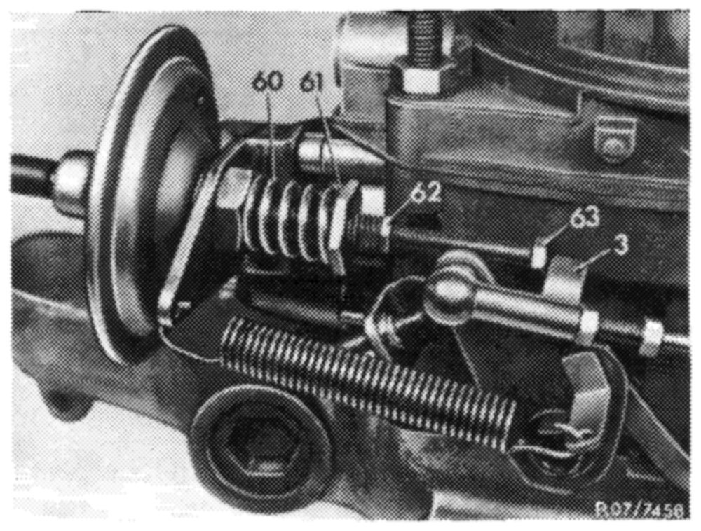
Connect revolution counter, increase engine speed to approx. 2500/min and let drop slowly, while watching vacuum governor on carburetor.
Control rod extending Control rod not extending starting at approx. starting at approx. 2000/min. Control rod = 2000/min or not rereturns below turning below 1800/min. 1800/min.
i
Testing vacuum lines
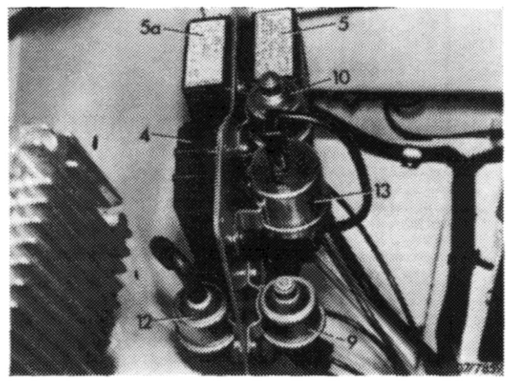
Test grey vacuum lines from carburetor to switch-over valve (10) and from switch-over valve to vacuum governor for condition and correct connection.
The vacuum originating line from carburetor should be plugged to center connection of switch-over valve (10).
Test switch-over valve (10)
Pull coupler from relay box (5a). Connect terminal 7 and 8. With ignition switched on, switch-over valve (10) should switch audibly and noticeably.
Testing RPM-switch 1800/2000/min in
RPM-relay (4)
Attention! Use a voltmeter to test electronic revolution counter. When using a test lamp, the RPM-switch may be damaged.
ld
14,2-100/6 USA 1973/74 F2
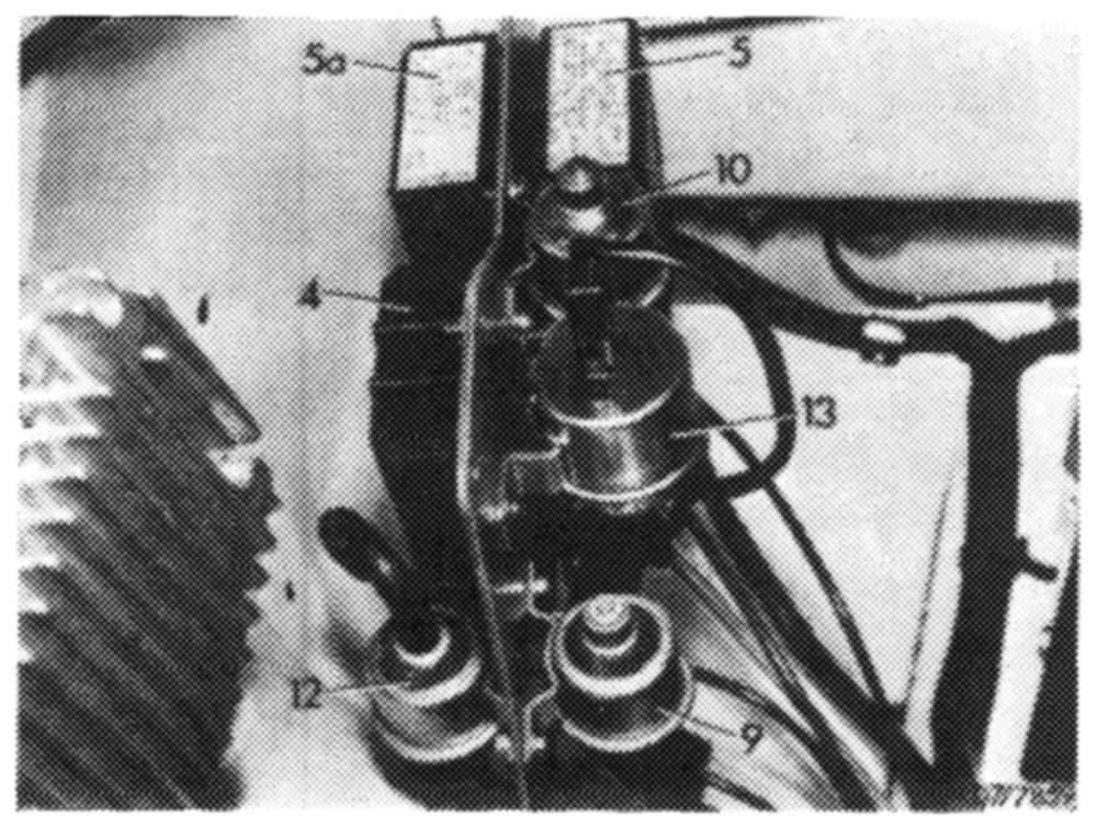
Pull coupler from grey switch-over valve (10), connect test cable to valve and put coupler back again. Connect voltmeter to test cable. Start engine and increase speed. Above approx. 2000/min, the voltmeter should indicate approx. 13 Volts.
When the speed is dropping, the voltmeter should move back to 0 Volt at approx. 1800/min.
If no voltage is measured on coupler of switch-over valve above 2000/min, repeat test without relay box (5a). For this purpose, pull coupler from relay box (5a) and connect voltmeter to terminal 2 and 3.
If a voltage of approx. 13 Volts is measured above approx. 2000/min, renew relay box (5a).
If no voltage is measured at speeds above 2000/min, renew RPM-relay (4).
eR
Testing throttle valve lift
Pull plug from temperature switch 100 °C (8) and connect to ground. Then increase speed to above approx. 2000/min. Watch vacuum governor.
Control rod Control rod not extending. extending.
=P
Renew relay box (5a).
=”
14.2–100/7 USA 1973/74 F2
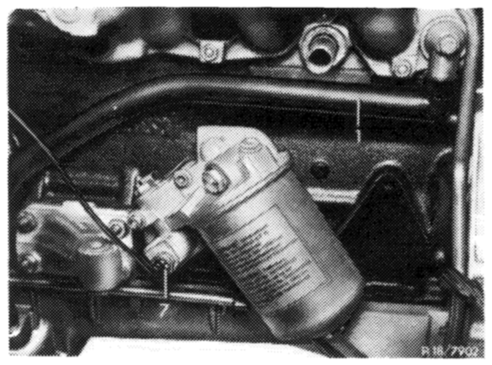
Testing choke cover-stepped heater
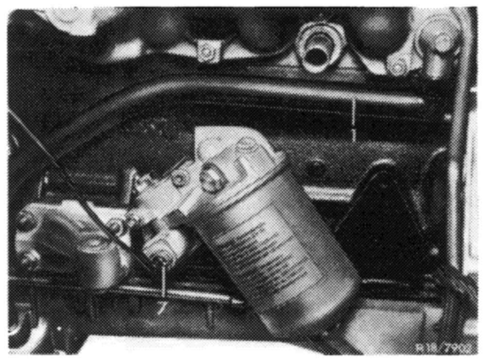
Separate plug connection of electric line to temperature switch 17 °C (7) in oil filter housing and connect to ground.
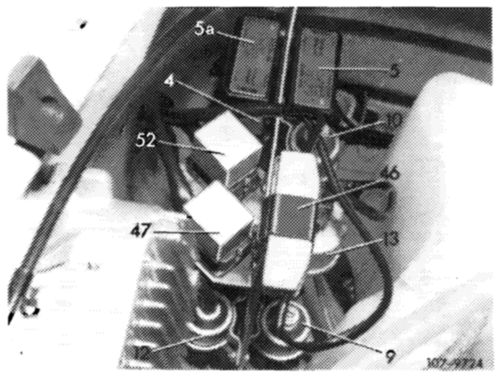
Relay (47 and 52) Relay (47 and 52) audibly switching. not switching.
ie, ul
Test relay for resistance of choke cover
(47) (front relay, short cable).
Connect voltmeter to output of resistance (46) and to ground. With the ignition switched on, voltmeter should indicate approx. 13 Volts. If no voltage is indicated, renew relay (47).
Loosen plug connection of electric line to temperature switch 17 °C¢ and connect to ground. Voltmeter should indicate approx. 5 Volts. Renew resistance, if no voltage is indicated.
If approx. 13 Volts are indicated, exchange choke cover on carburetor and repeat test.
End of test
14.2—-100/8 USA 1973/74 F2