Test program (model year 1980)
WIS 14-100
On/off ratio cannot be regulated, poor warm-up characteristics of engine, hunting For conplaints such as: at idle, engine not accepting gas or splashing during acceleration, proceed as follows:
Check lambda control.
Check air injection.
Check fuel evaporation control system.
Assumption: CIS injection system and ignition system in order.
Special tools
116 589 27 2100 Oil telethermometer
5 a
Allen wrench for hex socket screw 3mm – 000 589 14 11 00
Adapter for checking electric lines and components – 110 589 14 21 00
Conventional tools
Revolution counter, multimeter (volt-ohmmeter)
Lambda control tester KDJE—P 600
14.2-100/1 USA 1980/81 F2
Operational diagram model year 1980
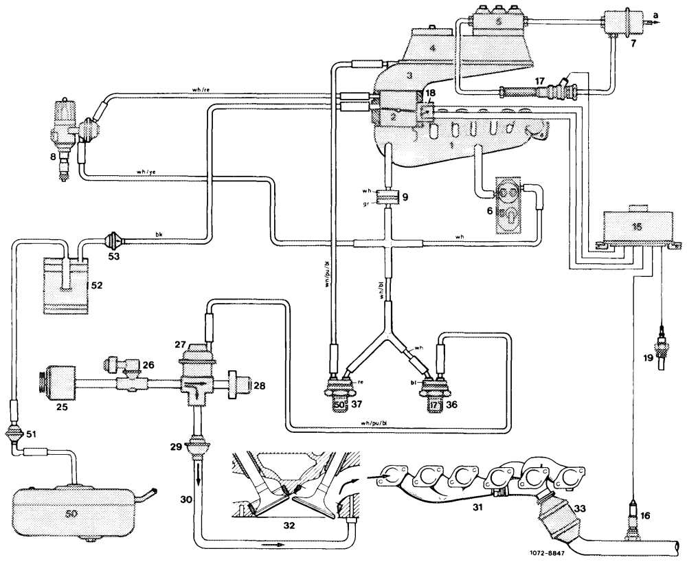
1 Intake manifold 16 Oxygen sensor 31 Exhaust manifold Color code 2 Throttle valve housing 17 Frequency valve 32 Cylinder head bk = black 3 18 Air guide housing Throttle vaive switch 33 Primary catalyst bl = blue 4 Air flow sensor 19 Temperature switch oil 36 Thermovalve gr =green 16 °C/61 °F 17 °C/62 OF 5 Volume distributor ye = yellow 6 Warm-up compensator 25 Air pump 37 Thermovalve re =red 50 °C/122 OF Damper 7 26 Pressure relief valve wh = white 8 Ignition distributor 27 Diverter valve 50 Fuel tank pu = purple 9 Orifice Damper filter (silencer) 28 51 Vent valve unit Control unit 5 29 Check valve 52 Charcoal canister 30 Injection line 53 Purge valve Leak-off connection
14.2–100/2 USA 1980/81 F2
Operational diagram model year 1981
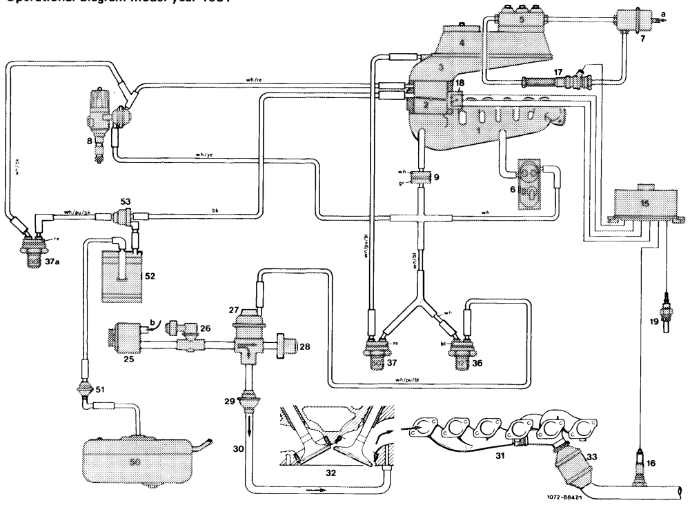
1 Intake manifold 18 Throttle valve switch 36 Thermovalve Color code
2 Throttle valve housing 19 Temperature switch oil 17 °C/62 OF bk = black
3 Air guide housing 16 °C/61 OF 37 Thermovalve bl = blue
4 Aijir flow sensor 25 Air pump 50 °C/122 OF gr =green
5 Fuel distributor 26 Pressure relief valve 37a Thermovalve ye = yellow
6 Warm-up compensator 27 Diverter valve 50 °C/122 OF re =red
7 Damper 28 Damper filter (silencer) 50 Fuel tank wh = white
8 Ignition distributor 29 Check valve 51. Vent valve unit pu = purple
9 Orifice 30 Injection line 52 Charcoal canister
15 Control unit 31. Exhaust manifold 53 Purge valve
16 Oxygen sensor 32 Cylinder head a Leak-off connection
17 Frequency valve 33 Primary catalyst b From air cleaner
A. Quick test with lambda control tester KDJE—P 600
The lambda control tester can be used for adjusting on/off ratio at idle, but also for a quick diagnosis of lambda control.
Connect lambda control tester to diagnosis socket and revolution counter. Connect oil telethermometer.
Note: If the specified nominal value is not attained, refer to quick test with adapter.
14.2-100/3 USA 1980/81 F2
| Scope of test | Actuation | Readout/nominal value | |
| a) Engine oil temperature | < 13 °C/55 OF | Engine at idle | Constant between 56–64 % |
| b) Simulation | Pull plug from temperature switch 16 °C/61 OF and connect to ground | Readout as above | |
| Warm-up control a) Engine oil temperature | > 20 °C/68 OF, oxygen sensor not yet ready for operation (< approx. 300 °C/572 °F) | Engine at idle | Constant between 46–54 % |
| b) Simulation | Separate plug of oxygen sensor | Readout as above |
Control at operating temperature
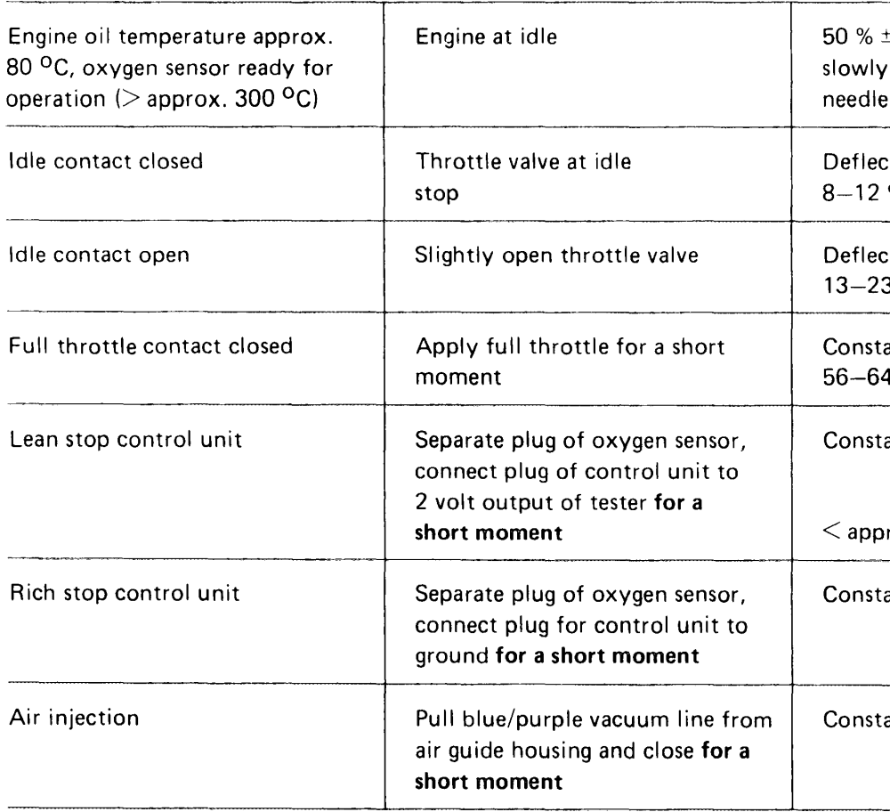
10% swinging
of needle approx. % around nominal value
of needle approx. % around nominal value
between %
< approx. 20 %
20 %
> approx. 87 %
approx. 87 %
14.2-100/4 USA 1980/81 F2
B. Quick test with adapter
Connect adapter to plug, control unit and multimeter to adapter.
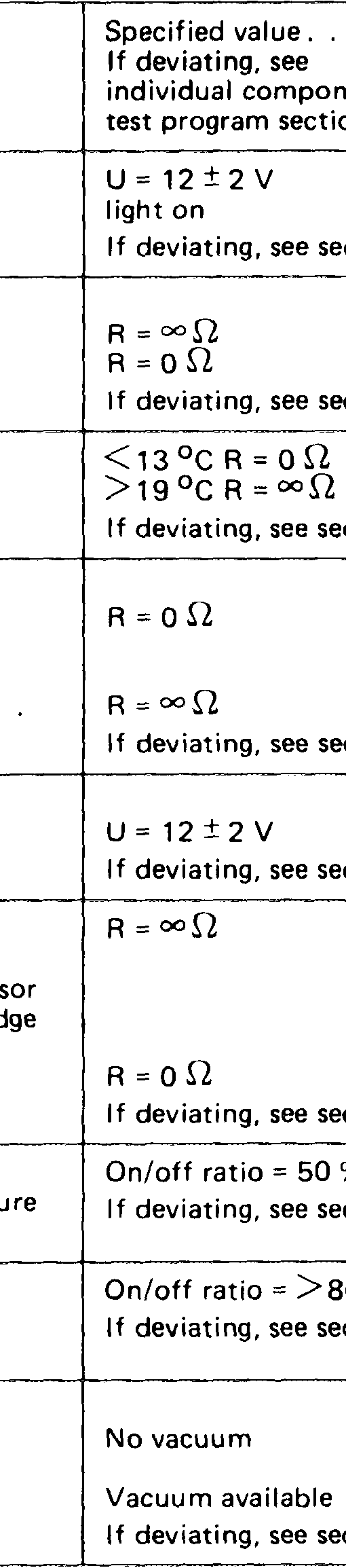
| Test set-up | Circuit or component tested | Setting of controls | . | |
| Adapter to Position 1 with voltmeter Adapter to position 2 with ohmmeter | Supply voltage Throttle valve switch | Ignition turned on Ignition off Idle position … Full throttle Position. .. | section |. sections IV and V. | |
| Switch 16 °C/ 61 OF | Ignition off | sections (t and III. | ||
| Adapter to position 3 with ohmmeter | Throttle valve switch | Ignition off Idle position… Advance slightly throttle linkage | sections 1V and V. | |
| Adapter to position 4 with voltmeter | Frequency valve | Ignition on Crank engine | sections VI and IX. | |
| Adapter to position 5 with ohmmeter Disconnect adapter and re-insert plug into control unit. Connect lambda control tester | Oxygen sensor probe cable and connection to electronic control unit | Ignition off Pull off oxygen sensor connection and bridge plug going to elec- tronic control unit Run engine until operating temperature is attained | sections VII and VIII. section X. | +10 % |
| Pull blue/purple vacuum line from air guide housing and close | Start engine for a short moment | section XI. | % | |
| Pull draw-off line (purge line) to throttle valve housing from charcoal canister | Start engine \die approx. 2000/min | section XII. | ||
14.2-100/5 USA 1980/81 F2
C. Component test program
Test section A
Test conditions: Connect adapter to plug, control unit and multimeter to adapter.
Connect oil telethermometer.
|. Testing voltage supply of control unit
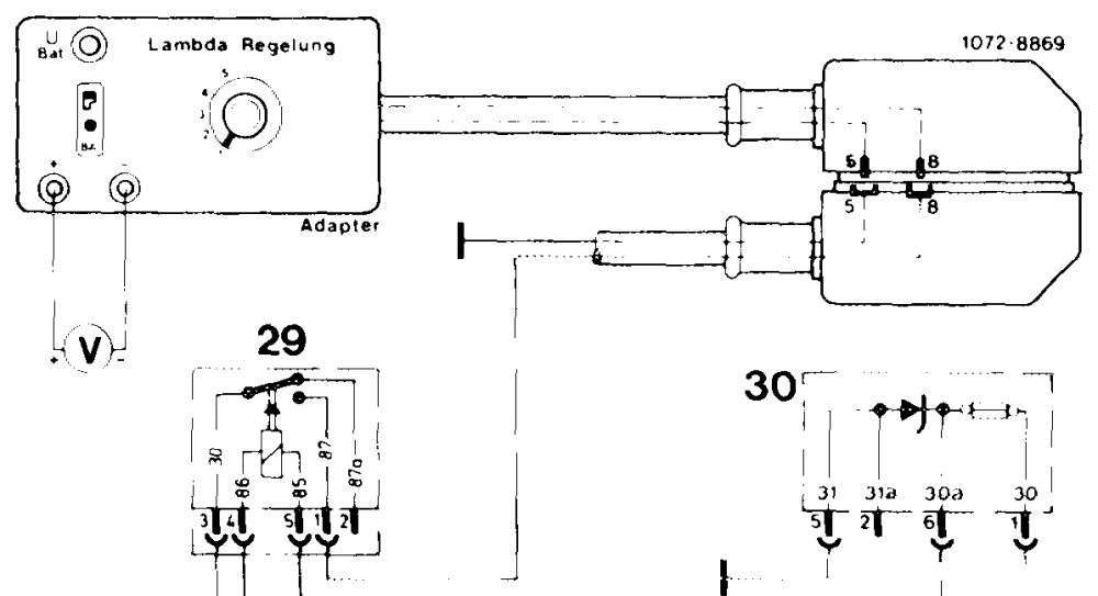

Rotary switch on adapter to position 1, meter to measuring range O—30 volts, switched on, read indicator.
Bo
Indicator lamp of adapter: Lighting up Not lighting lot Readout sens 8 2° approx. 12 volts Ovolt 630

EE
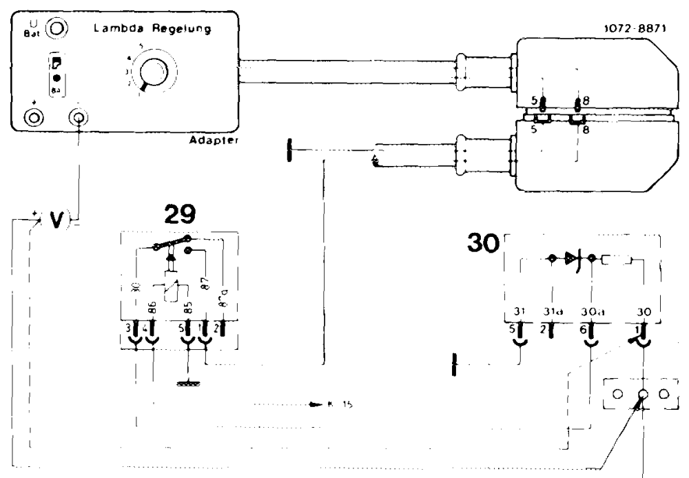
er
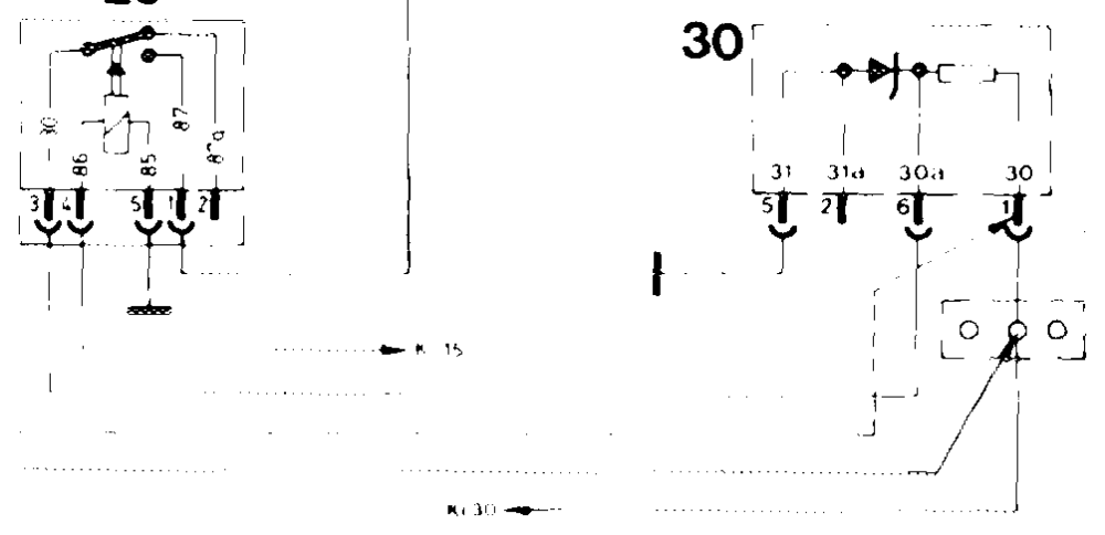
(positive) cable of voltmeter adapter. Measure voltage: on of engine harness (terminal of overload protection (30)
oe
Readout 12 volts O volt
of
Check line for break and correct, required. Readout approx. 12
14,.2–100/6 USA 1980/81 F2
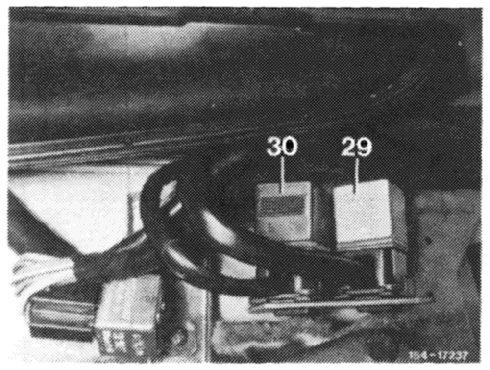

gl overload protection (30) to plug in manner that the voltage on terminal be measured with plus (positive) of voltmeter.
Readout 12 volts 0 volt
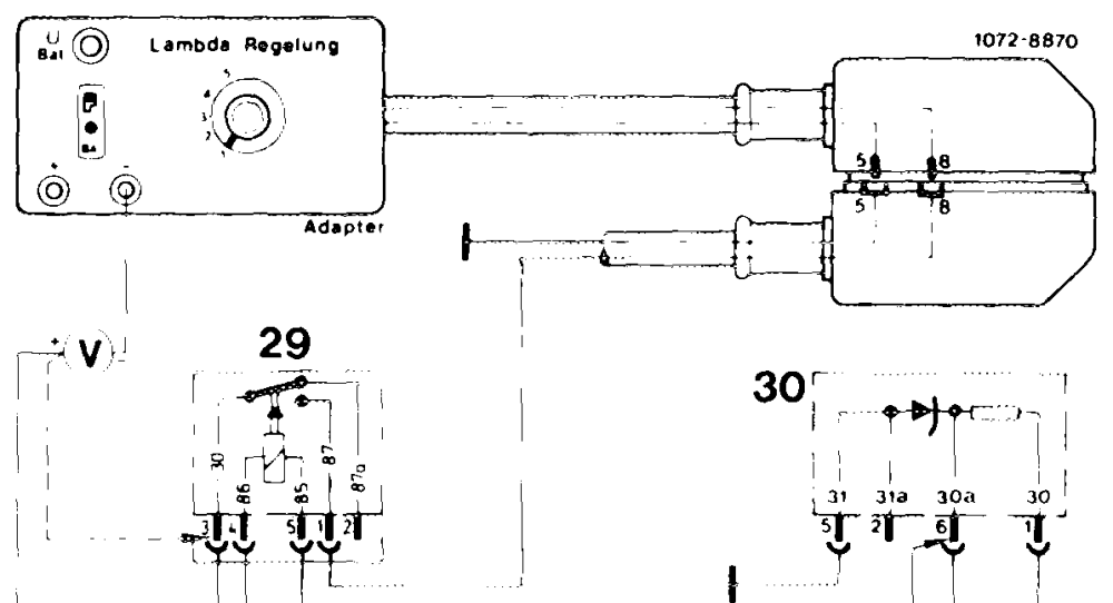
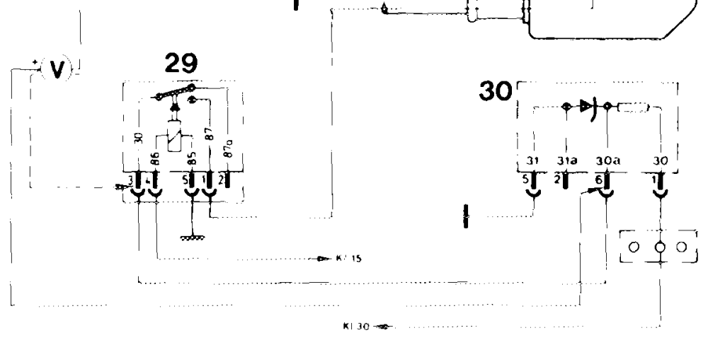
Renew overload protection (30). Readout approx. 12 volts —
Pn
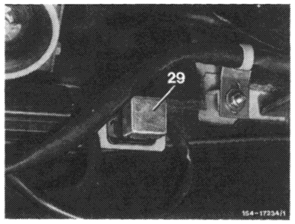
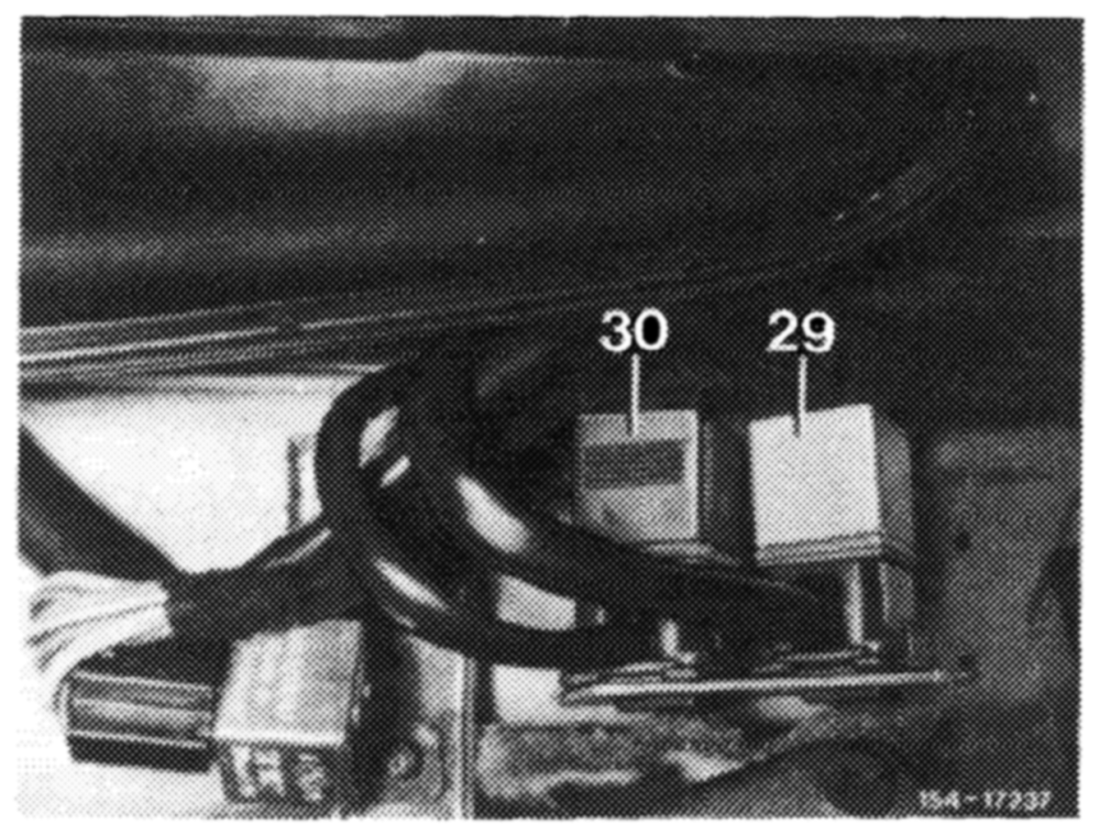
relay for voltage supply (29) to plug a manner that voltage on jack 3 can measured with plus (positive) cable of
Readout 12 volts 0 volt
Check line to overload protection for break and correct, if required. Readout approx. 12 volts. ce
te,
14,.2-100/7 USA 1980/81 F2
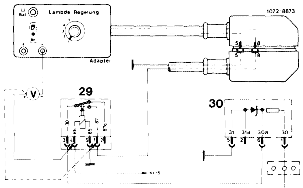

ee — —~ li, voltage on jack 4 with ignition on.
| Switched | 12 volts | Readout | Ovolt = | ||
| a a Check line to terminal 15 for break and correct, if required. Readout approx. 12 volts. | ae | — | |||
| voltmeter to jack 3 and 5. | ne | ||||
| 12 volts oe | Readout | 0 volt | |||
| Check ground connection line (jack for break and correct, if required. Readout approx. 12 volts. | a i, | aa | —_—— | ||
| relay for voltage supply (29) to such a manner that voltage on jack be measured. ee | a | a | |||
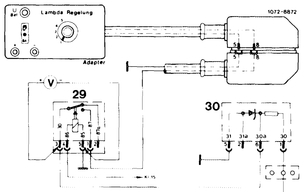
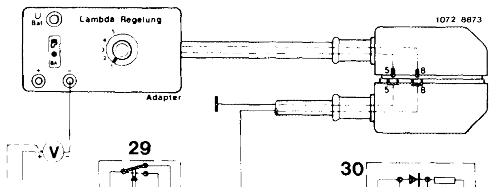
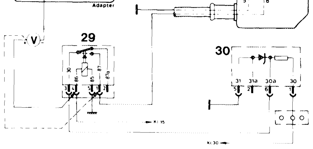
Readout 12 volts 0 volt
Renew relay. Readout approx. 12 volts.
lle,
14,2—-100/8 USA 1980/81 F2
og Connect voltmeter to adapter and check voltage.
Readout approx. 12 volts O volt
Check line from plug of relay voltage supply (29) to plug of control unit for break and correct, if required. Readout 12 volts.
End of test
il. Testing temperature switch oil 16 °C/61 OF
(engine oil temperature < 13 °C/55 OF)
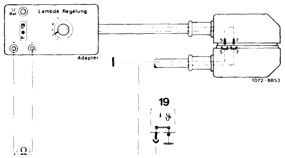
Rotary switch on adapter in position 2, multimeter on measuring range 0 — °° ohm, ignition switched off, disconnect plug of throttle valve switch, read indicator.
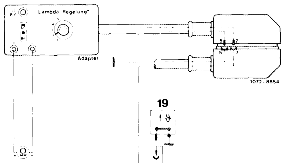
Readout 0 ohm co ohm
=P
Pull plug of temperature switch and connect to ground.
\f readout is O ohm, renew temperature switch.
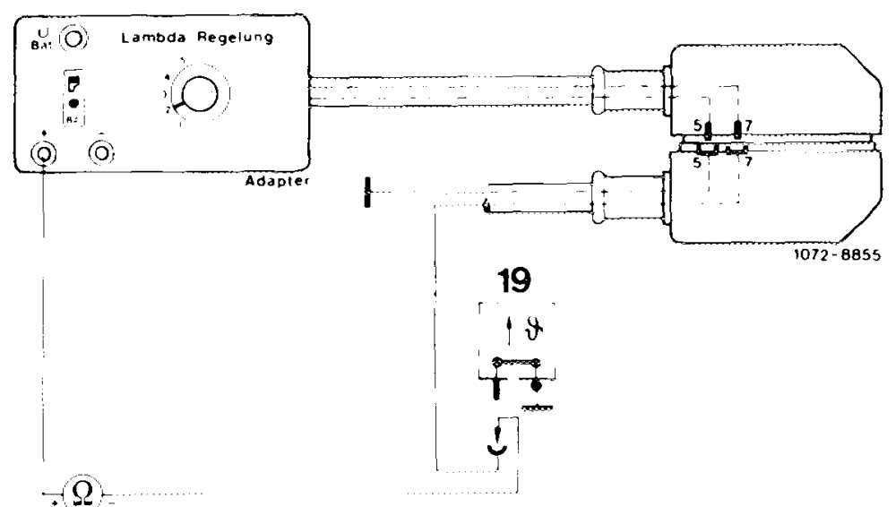
\f readout is °° ohm, check line of control unit plug (terminal 7) to temperature switch for break.
Testing temperature switch oil 16 °C/61 OF
(engine oil temperature > 20 °C/68 °F)
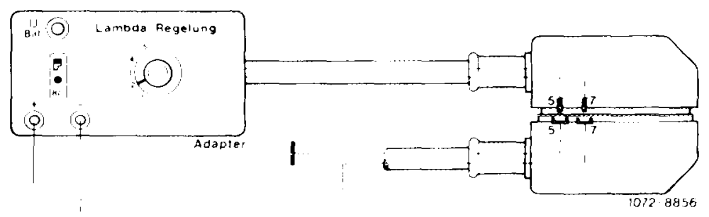
Rotary switch on adapter in position 2, multimeter on measuring range O—°° ohm, ignition _% 8 switched off. t+! “4 Disconnect plug of throttle valve switch (arrow). Read indicator.
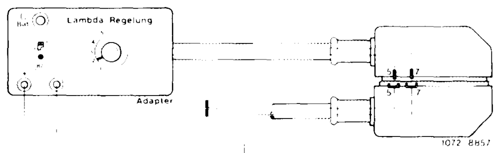
Readout 0 ohm
Pull plug on temperature switch.
If readout is °° ohm, renew temperature switch.
19 If readout is O ohm, check line from plug of tt control unit (terminal 7) to temperature switch a) for ground connection. 4 it iQe v
End of test
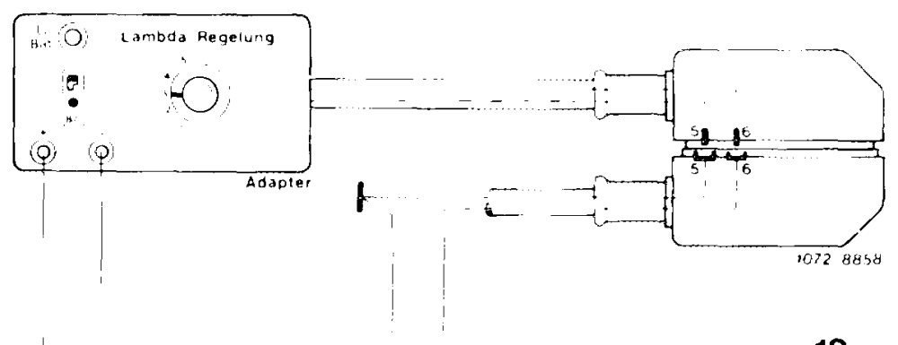
IV. Testing throttle valve switch (idle speed stop, engine oi! temperature > 20 °C/68 OF)
Rotary switch on adapter in position 3, multimeter on measuring range O—c° ohm, ignition 18 switched off.
Regulating linkage at idle speed stop. Read indicator.
| Readout | |
| Idle speed stop | |
| 0 ohm | co ohm |
| Lightly operate | |
| regulating linkage | |
| °° ohm | 0 ohm |
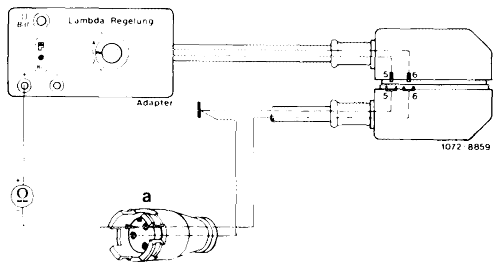
Pr”
Disconnect plug of throttle valve switch. Check lines from plug (a) to plug of control unit (terminal 6 or 15) for break according to wiring diagram. If lines are in order, renew throttle valve switch. =P
14.2—-100/10 USA 1980/81 F2
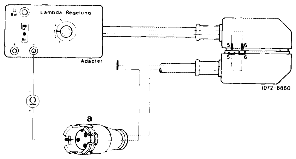
End of test
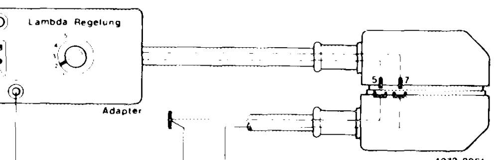
V. Testing throttle valve switch TH) (full throttle stop, engine oil temperature _ 2 > 20 °¢/68 °F)
a
Rotary switch on adapter in position 2, multi- 1072-8861 meter on measuring range O—°° ohm, ignition 18 switched off. ! em fT soem Plug on temperature switch oil pulled off. YQ: ron He Regulating linkage at full throttle stop. Read : indicator.
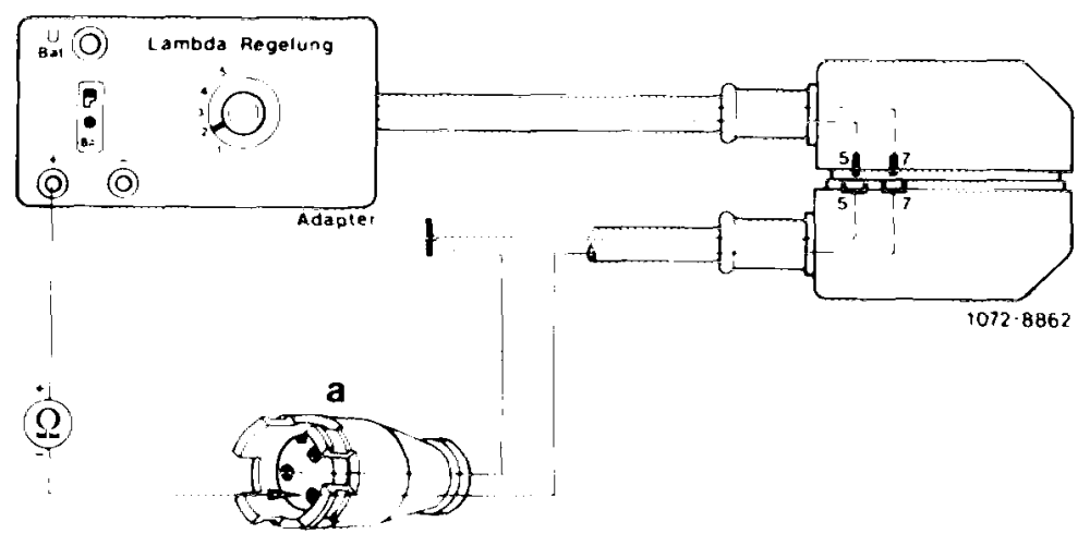
Readout Full throttle stop co ohm 0 ohm
Slightly release regulating linkage co ohm 0 ohm
eee ~ See _ _. eP _
Disconnect plug of throttle valve switch. . :
Check line from plug (a) to plug of control unit (terminal 7) for break. If line is in order, renew throttle valve switch.
End of test
14.2-100/11 USA 1980/81 F 2
Vi. Testing frequency valve
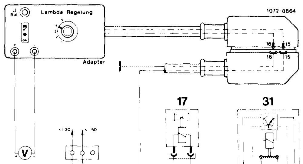
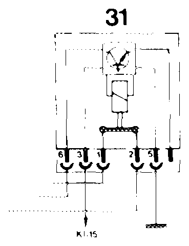
Rotary switch of adapter in position 4, multimeter on measuring range O—30 volts, ignition switched on, operate starter. Read indicator.
Readout approx. 12 volts O volt
=P
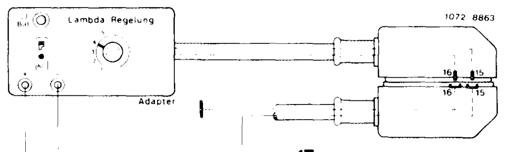
Pull plug from frequency valve and bridge. Operate starter. Readout 12 volts: replace frequency valve.
Readout 0 volt: switch off ignition, multimeter to measuring range O—°° ohm.
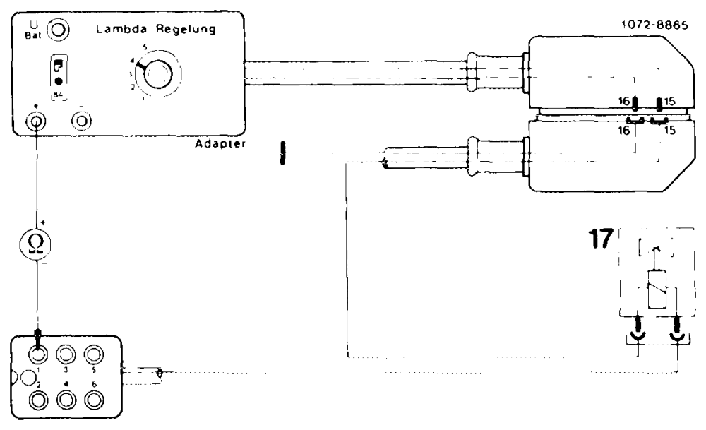
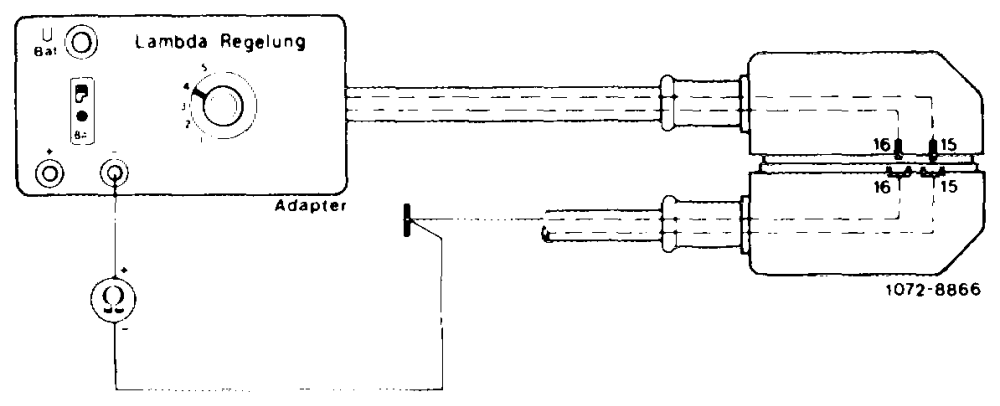
Test line from plug (control unit, terminal 15) to plug of electronic fuel pump relay (terminal 1), as well as line from plug of control unit vv (terminal 16) to ground connection point in legroom at the right under instrument panel for break.
End of test
14.2-100/12 USA 1980/81 F2
VII. Testing supply line to oxygen sensor
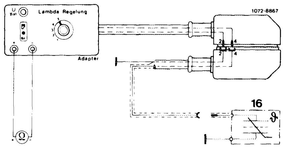
Rotary switch on adapter in position 5, multimeter on measuring range O—-° ohm, ignition switched off, plug oxygen sensor disconnected. Read indicator.
Readout °° ohm 0 ohm
=e
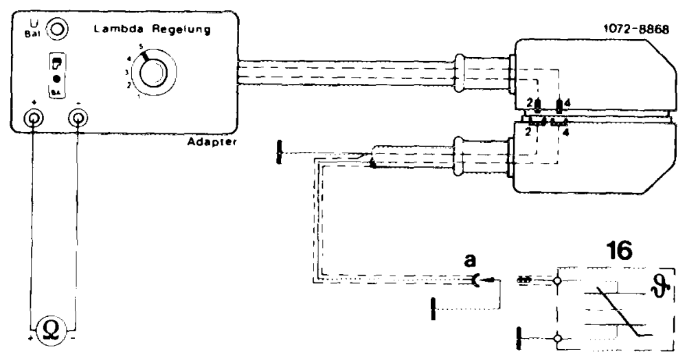
Line from plug of oxygen sensor to plug of control unit shorted.
Connect plug member (a) to ground.
Readout 0 ohm, line in order.
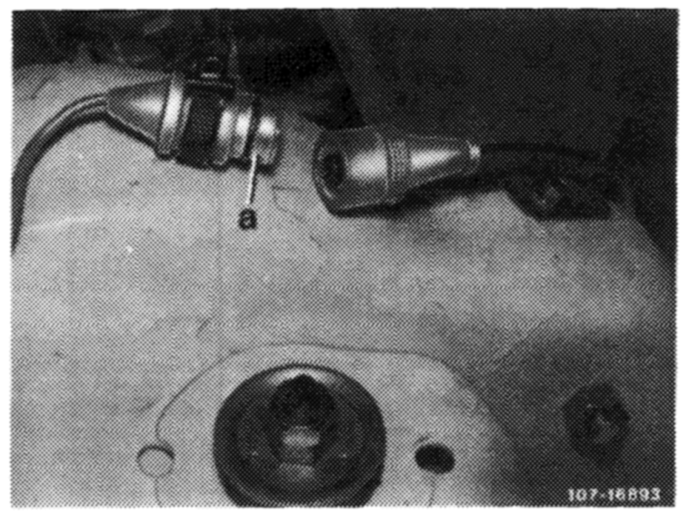
Readout °° ohm, line interrupted.
End of test
14,2—-100/13 USA 1980/81 F2
Test section B
Test conditions: Remove adapter, connect plug to control unit. Connect tester on/off ratio to diagnosis socket.
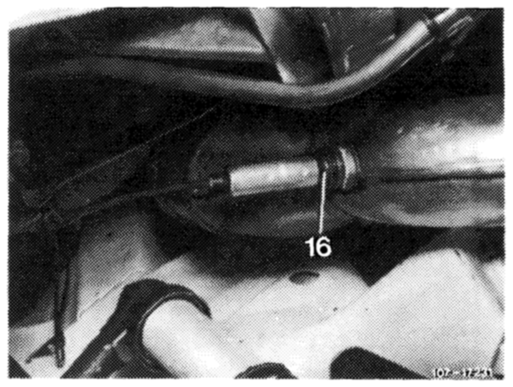
Start engine (plug of oxygen sensor connected).
Vit. Testing oxygen sensor
| Temperature of oxygen sensor below + 300 °C/ 572 OF. Read indicator on/off ratio. | |||
| constant 50 % | Readout | constant 92 % Ae | |
| Oxygen sensor shorted, renew oxygen sensor. | |||
| End of test 1X. Testing frequency valve (17) | |||
| Engine oi! temperature > 20 °C/68 OF. Engine at idle. Place one hand on frequency valve. | |||
| Frequency valve noticeably operating. | Frequency valve not operating. | ||
| Renew frequency valve. | |||
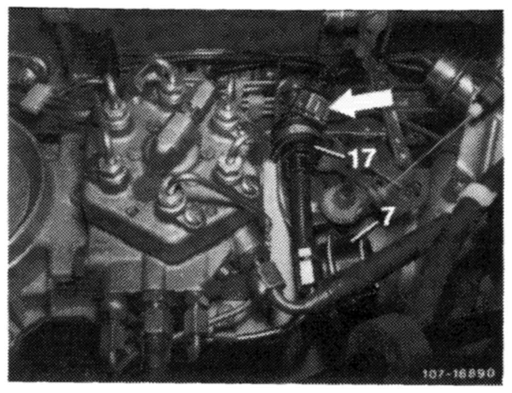
End of test
14.2-100/14 USA 1980/81 F2
X. Testing lambda control
Engine oil temperature approx. 80 °C/176 OF. Engine at idle (750 + 50/min).
Read indicator on/off ratio.
Readout between 40–60 % <40% or > 60% Constant 50 %
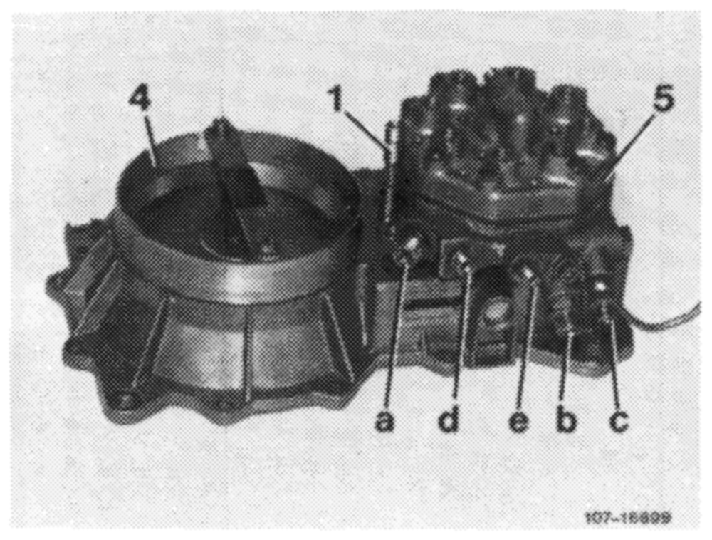
eae
Adjust on/off ratio on mixture regulating screw (1) in such a manner that readout is around 50+5%.
If on/off ratio cannot be regulated, check thermovalve 50 °C/122 OF (37) for passage. If passage is clear, renew control unit.
Readout constant 50 %, oxygen sensor defective, renew.
End of test
XI. Testing air injection
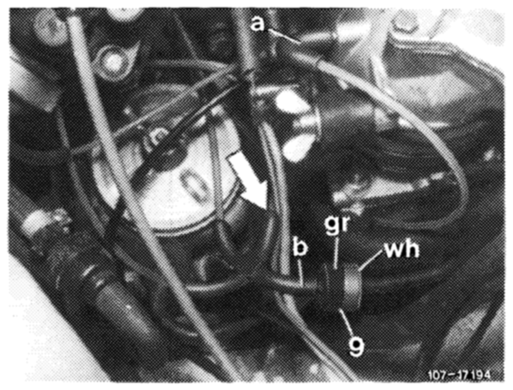
Engine oil temperature approx. 80 °C/176 OF, engine at idle (750 + 50/min), pull blue/purple vacuum line (a) from air guide housing. Close vacuum line with finger for a short moment.
Read indicator on/off ratio.
Readout Constant > approx. Remains constant 87 %
y+ oe
14.2-100/15 USA 1980/81 F2
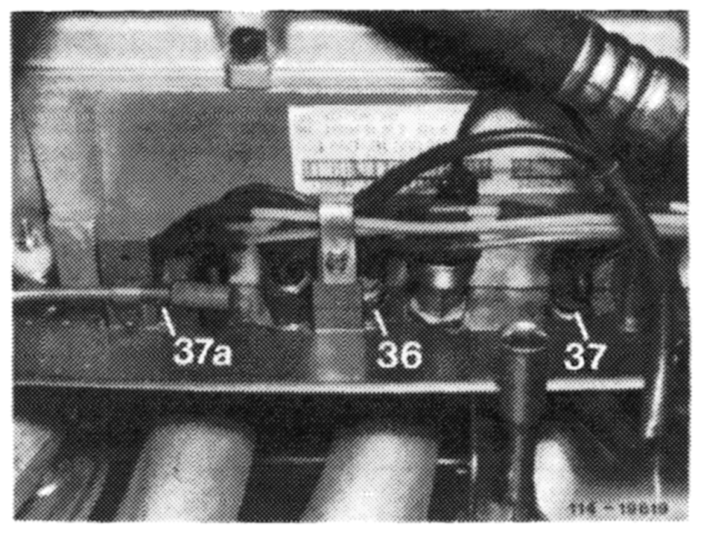
Testing vacuum lines
The blue/purple vacuum line from air guide housing leads to straight connection of thermovalve (37), the blue/purple vacuum line from diverter valve (27) leads to straight connection of thermovalve (36).
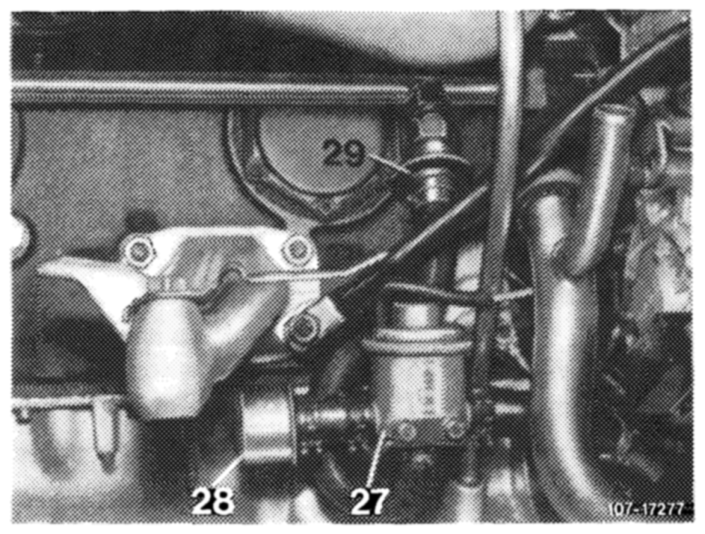
Thermovalves (36 and 37) are connected to the diagonal connections by means of a 3-point distributor. From there, a blue vacuum line leads to 4-point distributor, which is connected to the intake manifold by means of orifice (9) and a rubber hose.
Testing vacuum
Pull 3-point distributor from diagonal connections of thermovalves (36 and 37) and check for presence of vacuum at distributor. If there is no vacuum: blow out connection on intake manifold with compressed air.
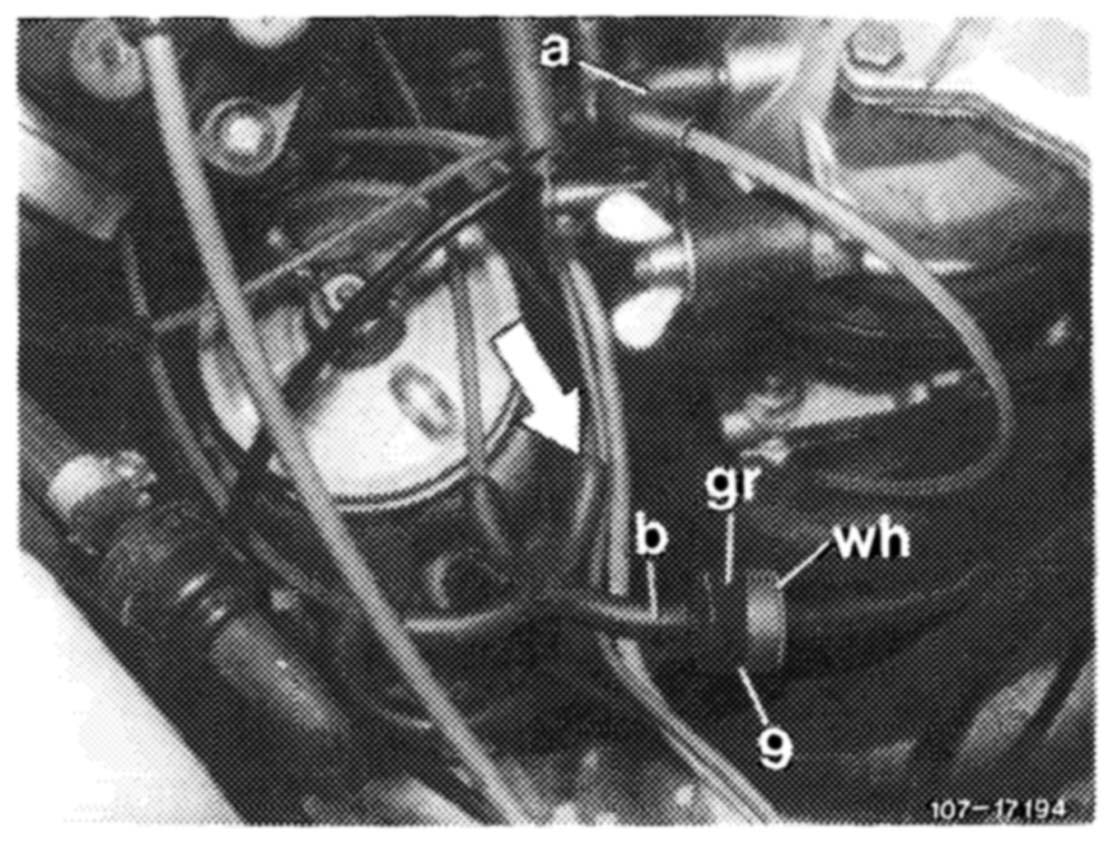
Check 3-point distributor, blue vacuum line, 4-point distributor, orifice (9) and rubber hose for passage.
If vacuum is present: check thermovalves (36 and 37) for passage and renew, if required.
If passage is available on both thermovalves, renew diverter valve (27).
\f readout of on/off ratio is still constant upon completion of these tests, check V-belt tension and delivery capacity of air pump.
End of test
14.2-100/16 USA 1980/81 F2
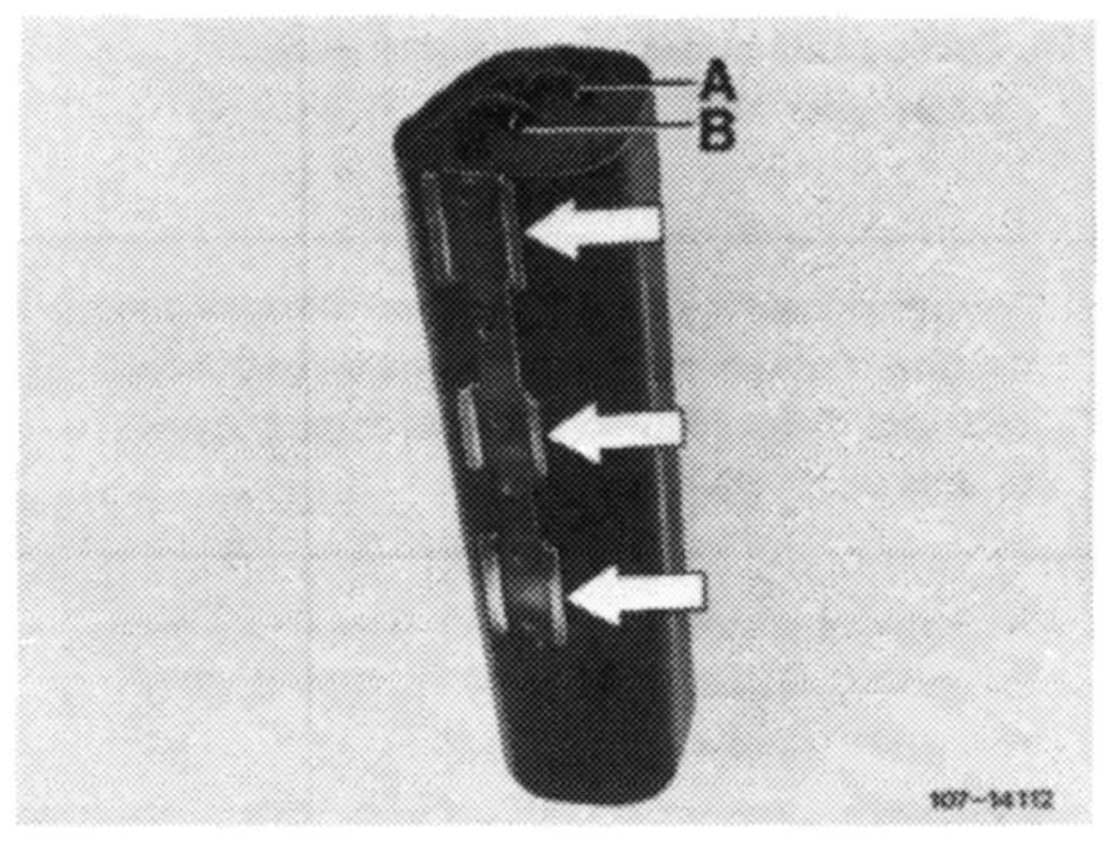
XII. Testing fuel evaporation control system
model year 1980
Pull draw-off hose (A) toward throttle valve housing from charcoal canister and keep closed with one finger. Slowly increase engine speed above approx. 2000/min.
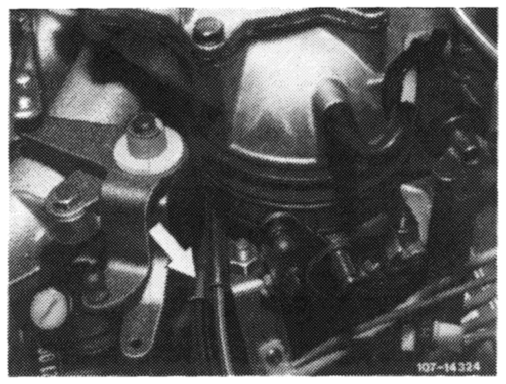
No vacuum at idle. No vacuum increase Increasing vacuum with increasing speed. with increasing speed.
Checking draw-off connection and purge valve
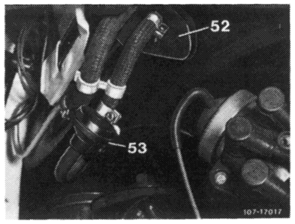
Draw-off connection should be plugged to throttle valve housing (arrow). Check hose for leaks and blow out connection on throttle valve housing.
If there is still no vacuum, pull off draw-off hose in front of purge valve (53) and repeat checkup.
If vacuum is present, renew purge valve.
End of test
14,2-100/17, USA 1980/81 F 2
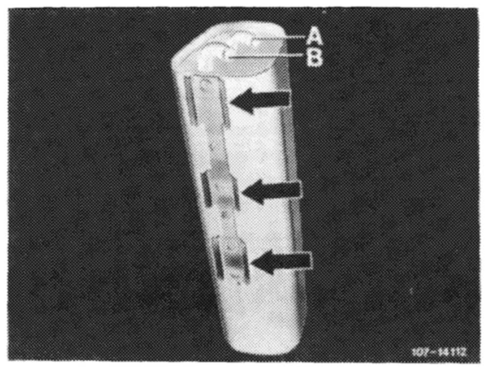
XII. Testing fuel evaporation control system
model year 1981
Pull off draw-off hose (A) toward throttle valve housing from charcoal canister and keep closed with one finger. Slowly increase engine speed to approx. 2000/min.
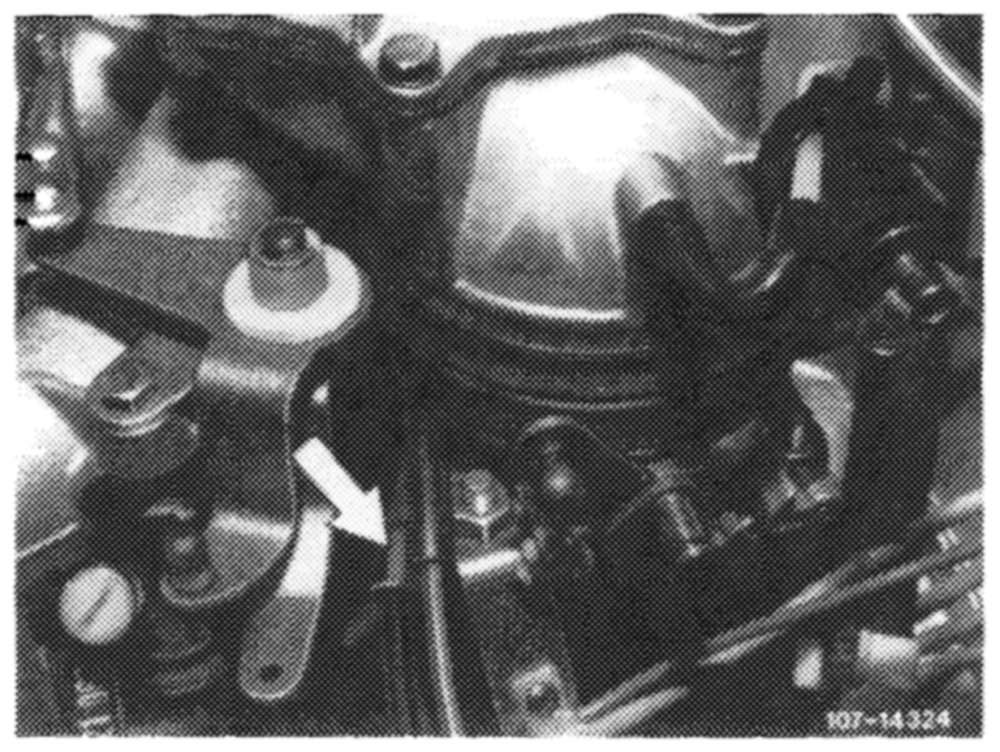
No vacuum at idle. No vacuum increase Increasing vacuum at increasing speed. at increasing speed.
Checking draw-off connection
Draw-off connection should be plugged to throttle valve housing (arrow). Check hose for leaks and blow through connection on throttle valve housing.
{f there is still no vacuum:
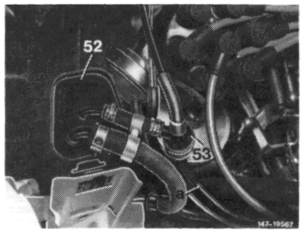
Checking thermovalve (37a) and purge valve (53)
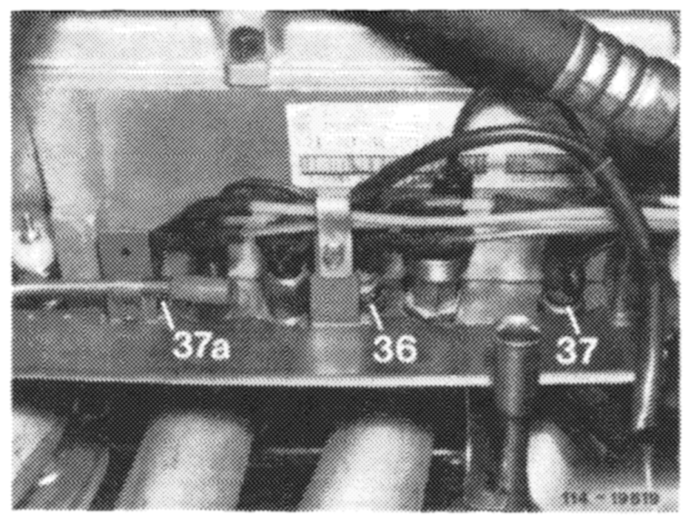
Pull off white/purple/black vacuum line on purge valve and check for presence of vacuum.
If vacuum is present, renew purge valve, if not, renew thermovalve.
End of test
14.2-100/18 USA 1980/81 F2