Adjusting accelerator control
WIS 30-1010
Operation no. of operation texts and work units or standard texts and flat rates: A. Vehicles without ASR 30-1010, B. Vehicles with ASR 30-1102.
A. Vehicles without ASR
a) Model 124
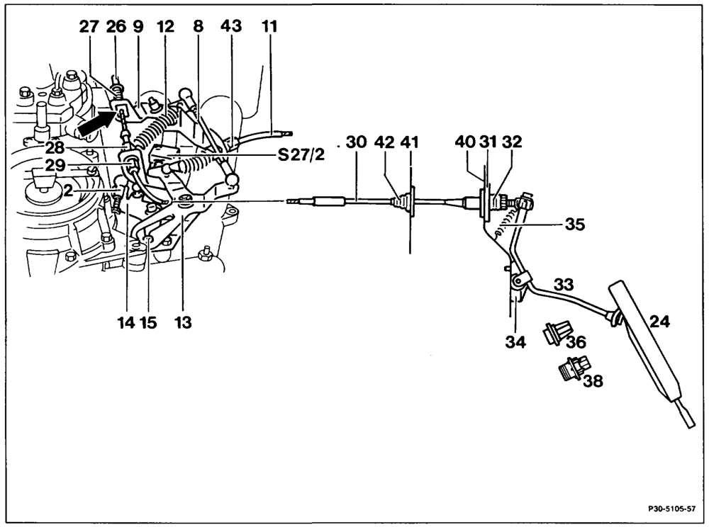
Accelerator control linkage and Bowden cable … check for ease of movement and bending; replace parts if necessary. Bowden cable (30) ………….–2-2000slacken. Driver spring must make contact free of tension at the nipple (26). If necessary, adjust with adjusting screw (29).
wie =RA 30.1142-1010/1
Connecting rod (2) detach. Check whether throttle valve is resting against idle speed stop. Connecting rod (2) re-attach free of tension. If necessary, adjust so that the roller (15) in the fulcrum lever (13) is resting free of tension against idle stop. Connecting rod (8) set to approx. 155 mm (measure from centre-tocentre ball socket); detach, attach for this step. Bowden cable (30) adjust. Nipple (26) must be resting free of tension on the compression spring (27). If necessary, adjust bowden cable (30) from inside vehicle with the adjusting nut (32). Grease between end piece and guide piece with anti-corrosion grease 000 989 87 51 00. Full throttle stop check. Detach control pressure cable (11) for automatic transmission. With engine switched off, depress accelerator to full throttle stop (36), with automatic transmission to stop on kickdown switch (38). The throttle valve lever must be resting against full throttle end stop when this is done. Perform necessary corrections with the adjusting screw (29) at the Bowden cable. Allow accelerator pedal to slowly move back into idle position. In this position the roller in the fulcrum lever must be resting free of tension against end stop and the microswitch (S27/2) must be operated. If necessary, adjust Bowden cable (30) from inside vehicle with the adjusting nut (32). If, when this check is performed the throttle valve lever does not touch full throttle end stop, adjust variable full throttle stop (36) (30-1010, section C).
wim =RA 30.1142-1010/2
Control pressure cable (11) for automatic transmission ………..0 02.00.0020 0085 adjust. Push back Bowden cable, then pull forward again until a stop is felt. Attach control pressure cable free of tension, if necessary adjust with adjusting screw (34). Idle stop ……… eee eee eee once again check.
Vehicles with Tempomat cruise control
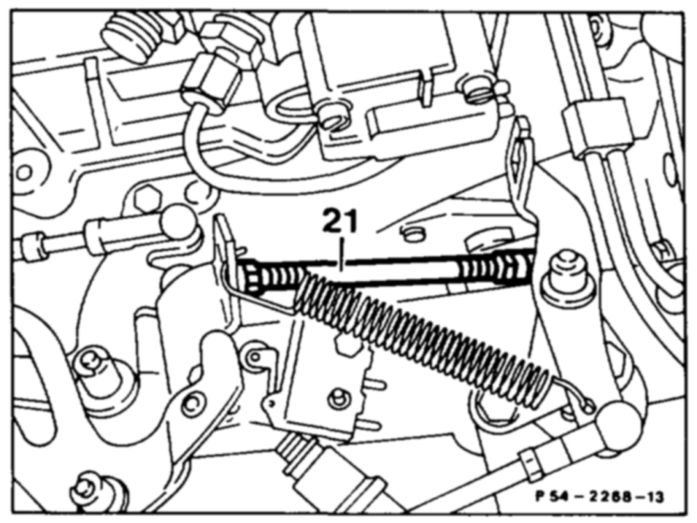
Check whether the actuator is resting against the idle stop of the cruise control. To do this, detach push rod (21) and push lever of actuator clockwise against idle stop. Whe the pushrod (21) is attached, ensure that the lever of the actuator is raised about 1 mm off the idle stop. Adjust push rod if necessary.
wim = RA 30.1142-1010/3
b) Models 107, 126
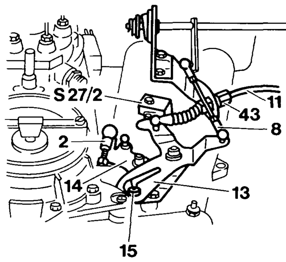
Model 107
Model 126
wim = RA 30.1142-1010/4
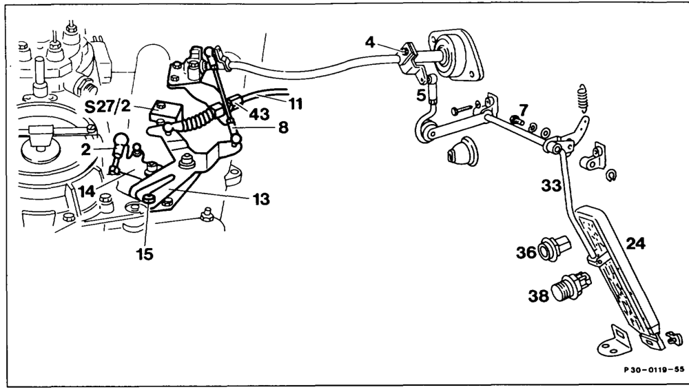
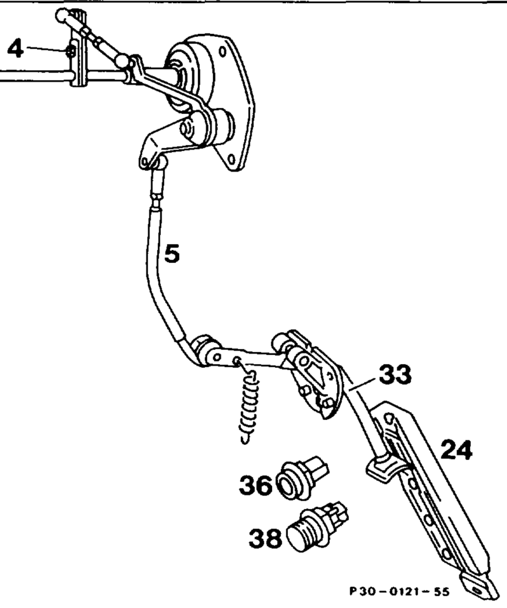
Accelerator control linkage …………….. check for ease of movement and bending. Replace parts if necessary. Connecting rod (2) detach. Check whether the throttle valve is resting against idle stop. Connecting rod (2) re-attach free of tension. If necessary, adjust so that the roller (15) in the fulcrum lever (13) is resting free of tension against the end stop. Connecting rod (8) adjust; to do this, detach, attach. Model 107 = 120 mm Model 126 = 105 mm Measured between ball socket centres. Full throttle stop check. Detach control pressure cable (11) for automatic transmission. With engine switched off, depress accelerator pedal to full throttle stop (36), on automatic transmission to the stop on the kickdown switch (38). The throttle valve lever must be resting against full throttle end stop when this is done. If necessary, slacken screw (4 or 7), adjust accelerator control linkage so that the throttle valve lever is resting against full throttle end stop. If the full throttle or idle speed end stop is not reached with this setting, adjust push rod (5) from the longitudinal accelerator control shaft to the accelerator pedal to the specified length, Model 107 = 105 mm Model 126 =220 mm, measured from centre of ball socket to centre of damping rings. As a check, allow accelerator pedal to slowly move back into idle position. in this position, the roller in the fulcrum fever must be resting free of tension against end stop and the microswitch (27) must be operated. If the throttle valve lever is not resting against full throttle end stop when this check is performed, adjust variable full throttle stop (36) (30-1010, section C).
wim §=RA 30.1142-1010/5
Control! pressure cable (11) for automatic transmission 2.0.2 ee eee adjust. Push back bowden cable, then pull forward again until a stop is felt. Attach control pressure cable free of tension, adjust if necessary with adjusting screw (43).
Vehicles with Tempomat cruise control
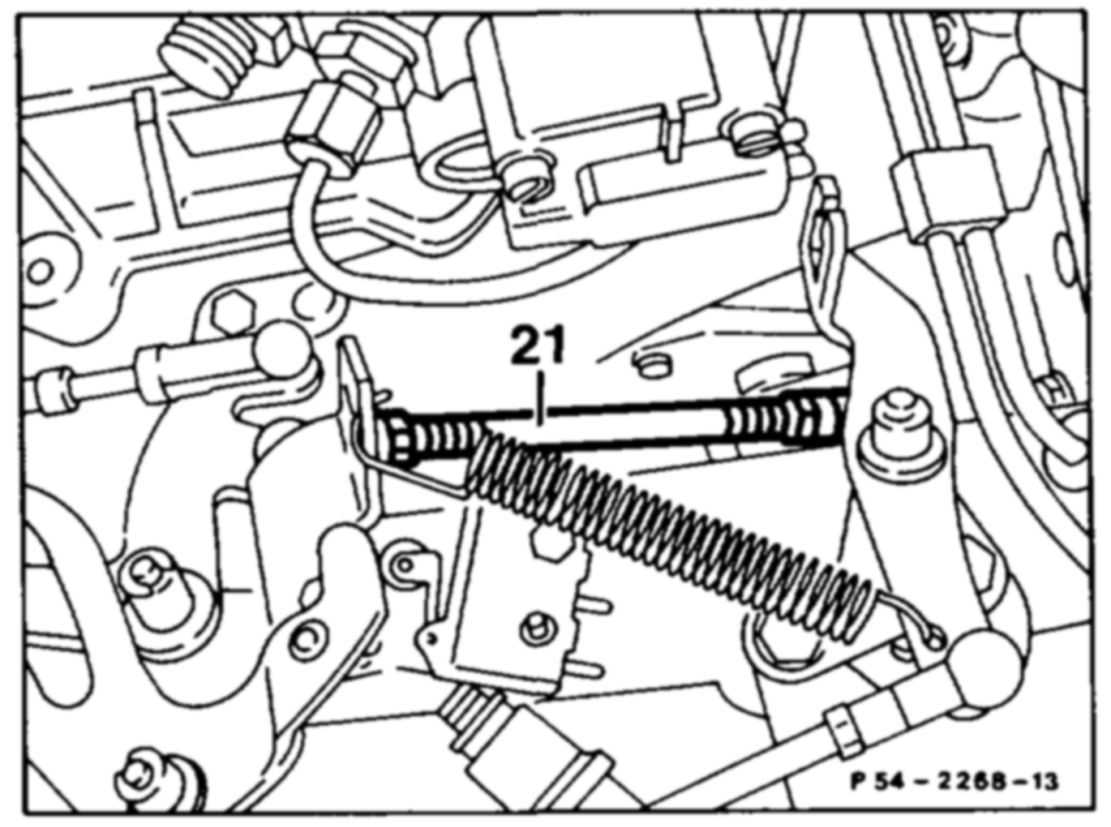
Check whether the actuator is resting against the idle stop of the cruise control. To do this, detach push rod (21) and push lever of actuator clockwise against idle stop. Whe the pushrod (21) is attached, ensure that the lever of the actuator is raised about 1 mm off the idle stop. Adjust push rod if necessary.
iim §=RA 30.1142-1010/6
c) Model 129 Vehicles with manual/automatic transmission and
with/without Tempomat cruise control
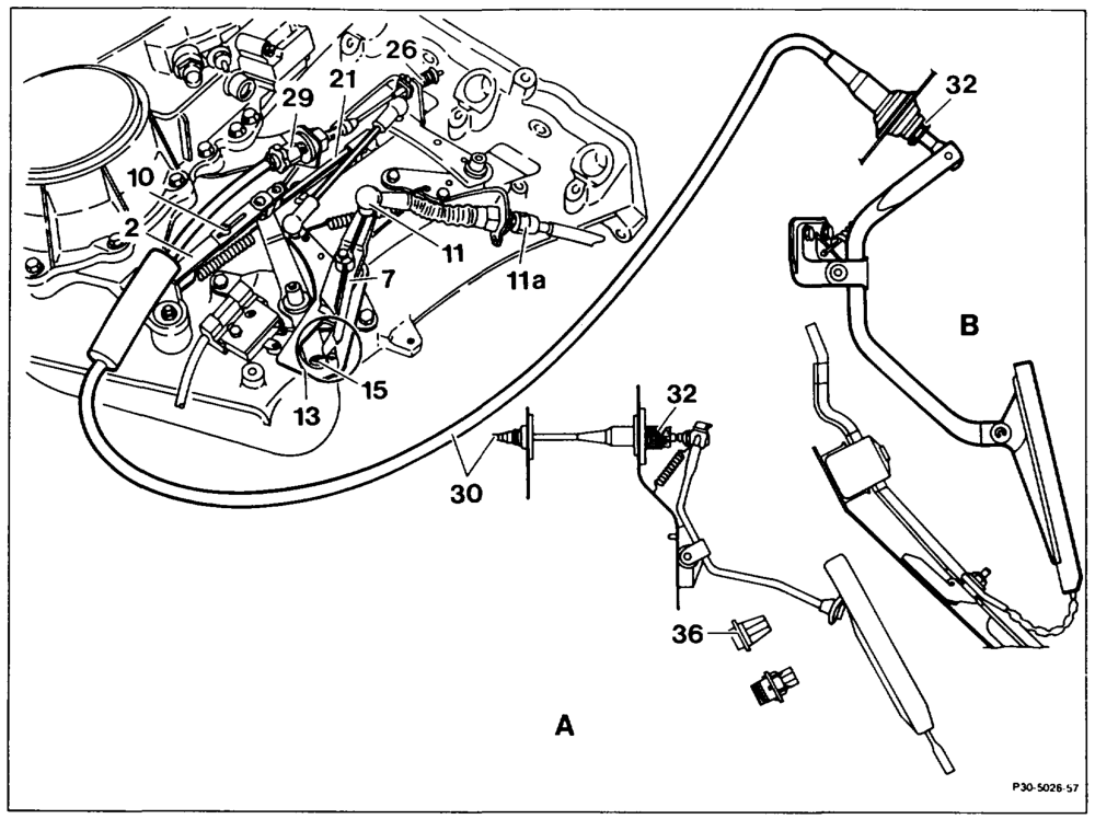
A. Model 124 B. Model 129
Accelerator control linkage and bowden cable check for ease of movement and condition. Replace parts if necessary.
If vehicle fitted with cruise control, check position of hose clip for oil-to-water heat exchanger. The accelerator control linkage must have sufficient clearance. Bowden cable (30) slacken. To do this, turn adjusting screw (29) until the driver spring (26) is making contact free of tension. Connecting rod (2) adjust. To do this, slacken clamping screw (10). Throttle valve lever must be resting against idle speed stop of the throttle valve body. Adjust connecting rod (2) so that the roller (15) in the fulcrum lever (13) is resting “free of tension” at the idle speed end stop. Tighten clamping screw (10).
wtime §=RA 30.1142-1010/7
Setting of cruise control check, correct if necessary. To do this, move throttle valve lever to idle speed stop, detach connecting rod (21) at the throttle valve lever and press actuator lever toward the engine as far as the stop in the idle speed position. Adjust connecting rod (21) so that the actuator lever has to be pulled back 1 mm off the idle speed stop in order to attach it. Control pressure bowden cable (11) adjust. To do this, alter position of adjusting screw (11a) until the arrow tips (circle) are exactly opposite. Bowden cable (30) adjust.
a) Full throttie manual transmission
Slowly depress accelerator into full throttle position. The throttle valve lever must be resting against full throttle end stop. If necessary, release adjustable full throttle stop (36) by turning to the left and pull stop bolt out slightly. Lock adjustable full throttle stop (36) in the position it has adopted by turning to the right.
b) Full throttle automatic transmission
With engine switched off, depress accelerator pedal from inside car until it touches the stop on the kickdown switch (S30/2) (do not operate kickdown switch!). When this is done, the throttle valve lever must
be 0.5 – 1.0 mm away from the full throttle stop
at the throttle valve body; adjust with adjusting screw (29) if necessary.
c) Idle speed When the accelerator is in the idling position, the driver spring (26) must be making contact free of play; set with the adjusting nut (32) from inside the car, if necessary.
wtp §=RA 30.1142-1010/8
B. Vehicles with ASR
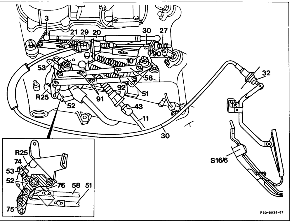
Accelerator control linkage and bowden cable check for ease of movement and condition. Replace parts if necessary. Bowden cable (30) …………….2.–. slacken. To do this, turn adjusting screw (29) until the compression spring (27) is making contact free of tension.
Connecting rod (21) ……………-000adjust. To do this, slacken clamping screws at connecting rod (21) and at connecting rods (51, 58). The throttle valve lever must be resting against idle end stop of the throttle valve body. Ignition: ON. This causes actuator lever to adopt „idle position.” Now fix length of connecting rod (21) by tightening the clamping screw.
Ignition: OFF
wie =RA 30.1142-1010/9
Connecting rod (51, 58) adjust. To do this, move levers (52, 53) to the respective „idle stop” (74, 75) at the position sensor (R25).
AN The levers must not move away from the idle stops during the adjustments.
Swivel lever (10) clockwise until idle travel rod (20) is pulled fully apart. Adjust connecting rod (58). To do this, move the slackened clamping screw (91) sufficiently toward position sensor (R25) until the stop pin (92) in the oblong hold is resting against the stop. Tighten clamping screw (91). Then, adjust connecting rod (51). To do this, push lever (90) lightly as far as the stop on the lever (10). Tighten clamping screw (91) in this position. Control pressure cable (11) adjust. Turn adjusting screw (43) sufficiently until the arrow tips (see enlarged detail) are exactly opposite. Bowden cable (30) ………..-….—00adjust.
a) Full throttle
Ignition: ON
With engine switched off, depress accelerator pedal from inside car as far as the stop on the kickdown switch (S16/6) (do not operate kickdown switch!). When this is done, the lever (53) must rest free of tension against the full throttle stop (76) of the position sensor (R25). If necessary, alter adjusting screw (29).
b) Idle speed
Ignition: ON
With accelerator pedal in idle position, there should just be no more play at the compression spring (27). If necessary, adjust with adjusting nut (32) from inside car.
wii §=RA 30.1142-1010/10
Bowden cable (30) grease between end piece and guide piece with anti-corrosion grease 000 989 87 51 00.
Note If driving faults occur when using the Tempomat cruise control on’ vehicles with ASR and cruise control, perform Tempomat cruise control test program (30-7300).
C. Adjusting variable full throttle stop

P30-5030–13
Variable full throttle stop (36) …………… release in footwell by turning to the left and pull stop pin out slightly. Accelerator pedal …………-…2.-.00slowly depress to full throttle position. The throttle valve lever must rest against full throttle end stop. Variable full throttle stop (36) …………… engage in the adopted position by turning to the right.
wie = RA 30.1142-1010/11
Notes Models 107, 124, 126 A modified shape of fulcrum lever is fitted (arrow) as standardization with all engines 103.
Production breakpoint: January 1986
Model Engine Engine end no. Engine end no. automatic transmission manual transmission
107.041 103.982 000260 001309
124.026 103.940 003470
124.030/090 103.983 017983
126.020 103.941 002120
126.024/025 103.981 006916
Models 107, 124, 126, 201
Tempomat cruise control connecting rod between accelerator control lever and drive lever actuator shortened by 6 mm (facilitates installation).
Production breakpoint: June 1989 Model Engine Engine end no. automatic transmission
107.041 103.982 011004
124.026 103.940 067516
124.030/050/090 103.983 171904
126.020 103.941 013700
126.024/025 103.981 089887
201.029 103.942 031433
wim = RA 30.1142-1010/12
Models 124, 126, 129, 201 with ASR and
automatic transmission Return spring between bearing bracket and relay lever with greater spring force.
Production breakpoint: August 1989
Model Engine ’) Engine end no. manual transmission
124.026 103.940 069894
124.030/050/090 103.983 180608
126.020 103.941 014104
126.024/025 103.981 095354
129.060 103.984 000219 201.029 103.942 034855
1) Except engines 103.943/985
Models 124, 126, 129, 201 with Tempomat
cruise control
As of November 1989, indefinite production breakpoint, a modified rubber seal is fitted between coding connector and Tempomat cruise control unit (recognition feature: color grey, previously black).
Models 124, 126, 129, 201 with ASR and
automatic transmission (without GS») Connecting rod between accelerator control lever and relay lever has standardized shape for M103 and M104.
Production breakpoint: 07/90
Model Engine +) Engine end no. automatic transmission
124.026 103.940 086670
124.030/050/090 103.983 218642
126.020 103.941 015720
126.024/025 103.981 122078
129.060 103.984 001421 201 -029 103.942 049769 ’) except engines 103.943/985
wim = RA 30.1142-1010/13
Models 124, 126, 129, 201
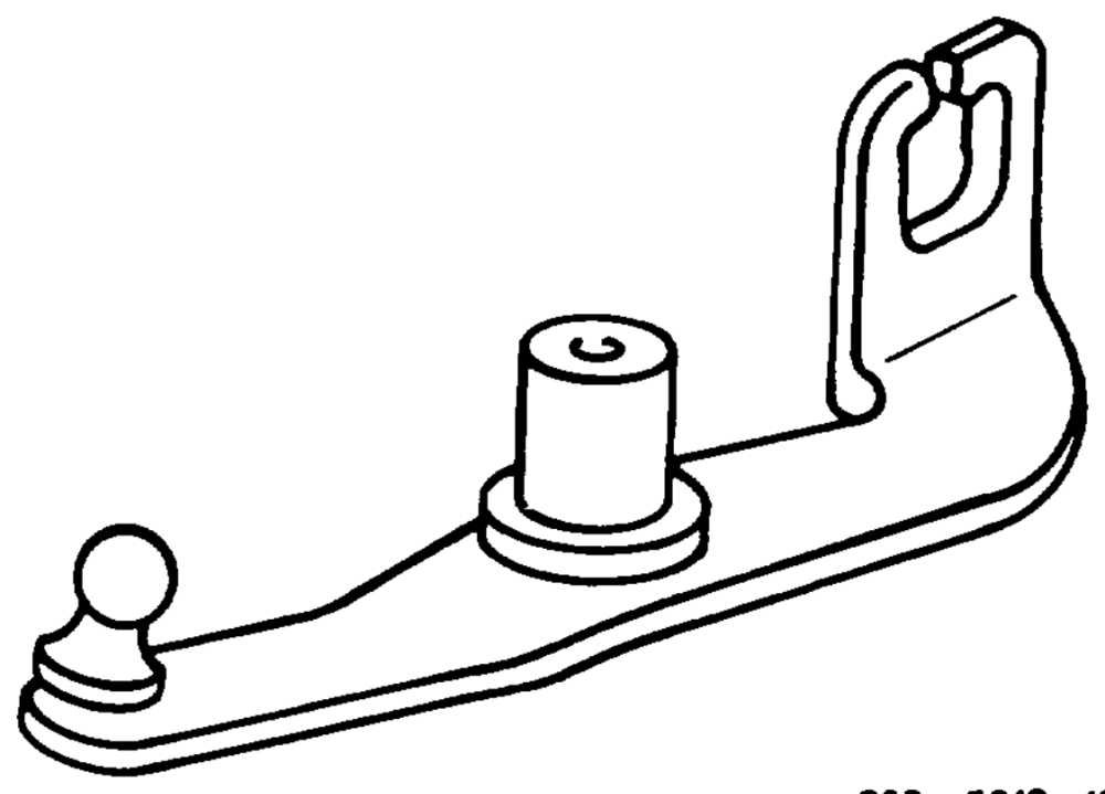
Ball stud at relay lever lengthened.
P30 — 5010–13
Production breakpoint: January 1991
Model Engine Engine end no. automatic transmission
124.026 103.940 094893
124.030/050/090 103.983 236880
126.020 103.941 016364
126.024/025 103.981 132889
129.060 103.984 002326
201.029 103.942 056221
Models 124, 201
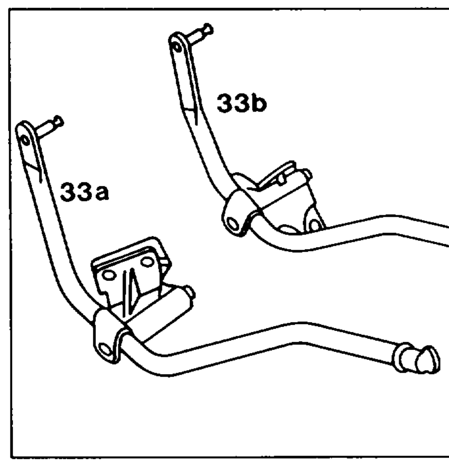
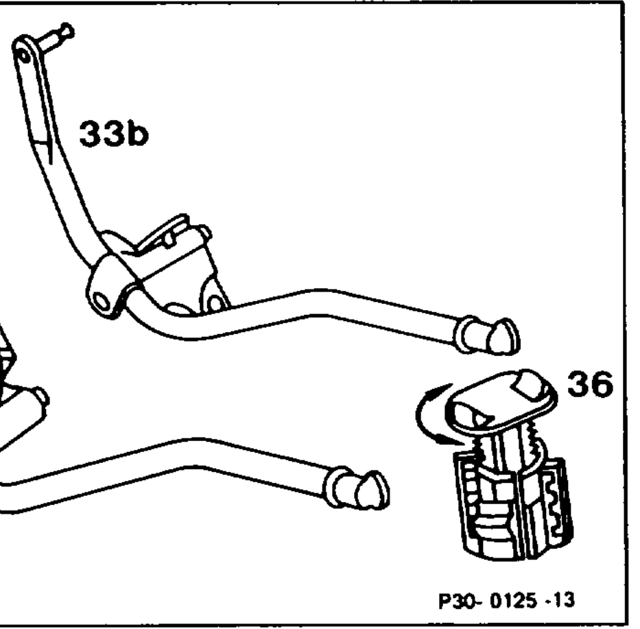
Improvement in metering and adjustability by converting accelerator pedal lever (extending), mounting and variable full throttle stop with enlargement of pedal travel by 3° in the direction of full throttle.
33a Accelerator peda! lever model 124 33b Accelerator pedal lever mode! 201 36 Full throttle stop
Production breakpoint: 11/88
Model As of vehicle ident end no. As of vehicle ident end no. A F
124.026/030/050/090 907 056 096 908 124.226/230/290
201.029 473 115 576 183