ABS/ASR and electronic accelerator pedal initial test
WIS 30-0360
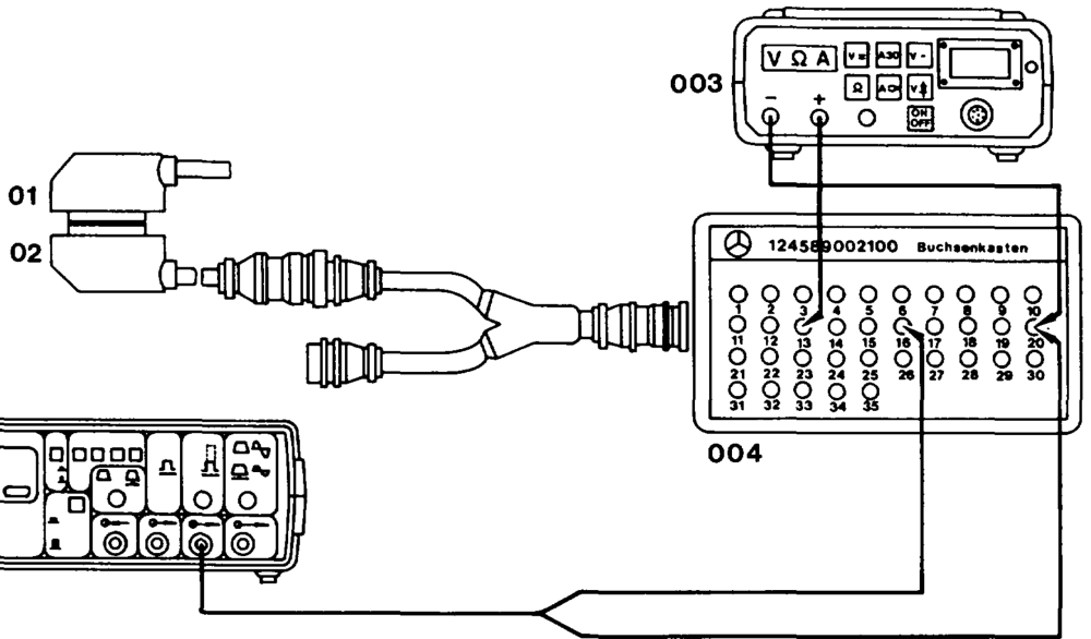
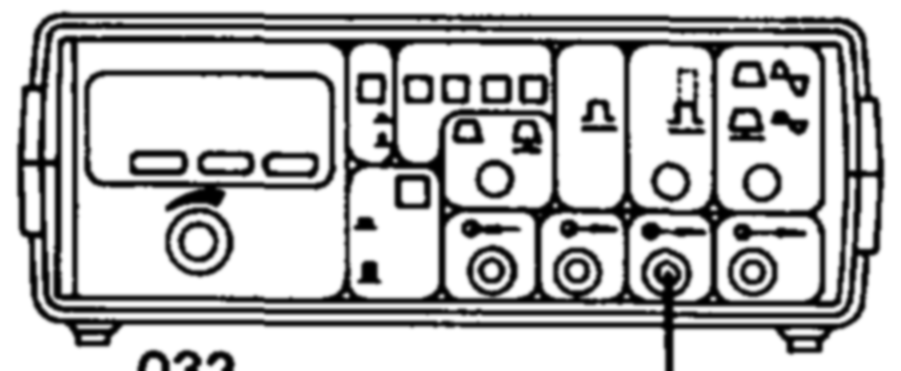
Operation no. of operation texts and work units or standard texts and flat rates:
032
P300018 -SSA
Connection diagram function generator and multimeter to contact box
01 Vehicle cable harness (ABS/ASR control unit) 003 Multimeter
02 Test cable 645 589 02 63 00 004 35-pin contact box 032 Function generator
Special tools
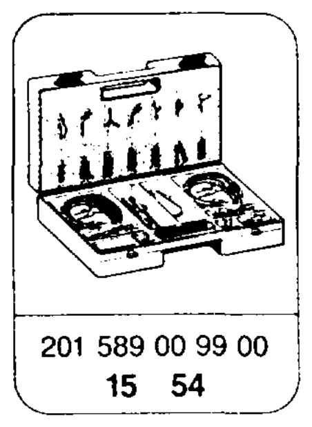
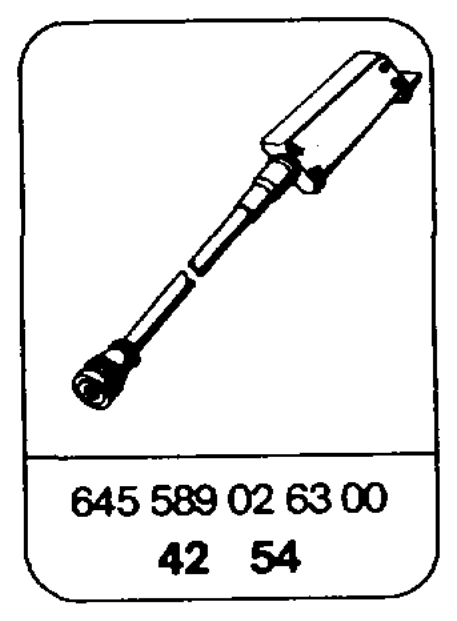
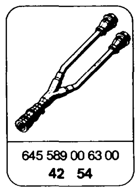
rc N K 54 – 124 589 00 21 00
iim §=RA 30.1142-0360/1
Commercially available tools and testers (see Workshop Equipment Manual) Designation e.g. Make, order no.
Multimeter Sun, DMM-5
Function generator Sun, OTR 8416
Symbols for testers
Symbols for test mode with multimeter
35-pin contact box Function generator, square-wave Contact signal ams =@®*+ — Multimeter, DC voltage test mode
| Test | Test scope | Test connection | Operation/ | Specifi- | Possible cause/Remedy |
| step | Requirement | cation | |||
Throttle N4/1
1.0 Disconnect
valve
ABS/ASR signal 20 16 control unit,
from/to
connect
electronic
frequency accelerator generator.
pedal
AN
control unit
red cable to contact 16. Set f=200 Hz U=10 V.
Ignition: ON 47V Test wiring between N4/1 Full throttle and ABS/ASR control unit actuator (N30/1) and electronic
20 13 must accelerator pedal (N4/1) for move open circuit/short circuit. only approx. If specification is achieved: 50% Perform ABS/ASR test from idle program. speed. If specification is not achieved: Perform electronic accelerator pedal test program (30-1050).
wie = RA 30.1142-0360/2