Testing electronic engine control
WIS 30-1050

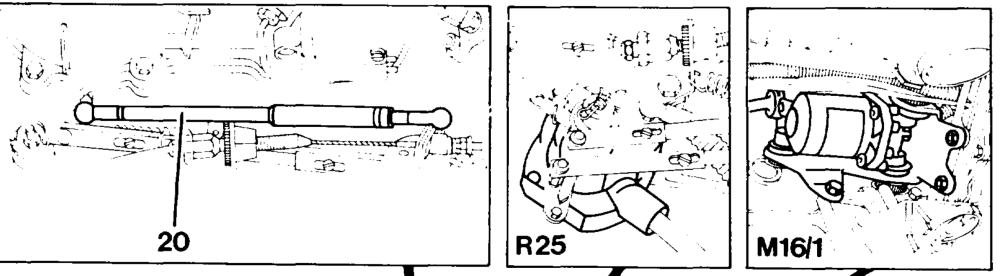
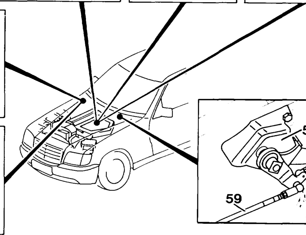
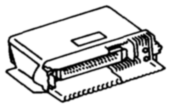
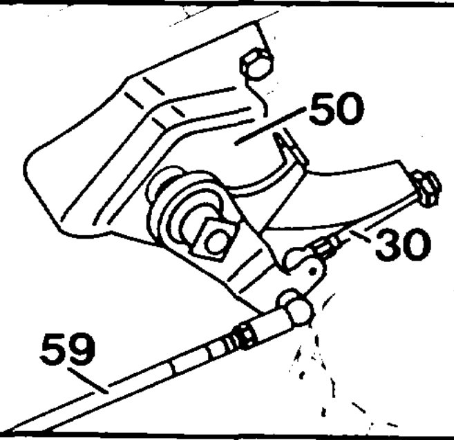
Preceding work: Operation no. of operation texts and work units or standard texts ABS/ASR and electronic accelerator pedal initial test and flat rates: (30-0360).
P30-5044–57
Model 124
M16/1 Electronic accelerator pedal (EFP) actuator 20 Idle travel rod (redundancy rod) N4/1 Electronic accelerator pedal (EFP) control unit 30 Bowden cable (RHD, onty models 126.024/025) N16/4 Fuel pump relay kickdown shutoff 50 Fire wall bearing (RHD, only models R25 Electronic accelerator peda! (EFP) position 126.024/025) sensor 59 Connecting rod (RHD, only models 126.024/025)
«iim §=RA 30.1142-1050/1
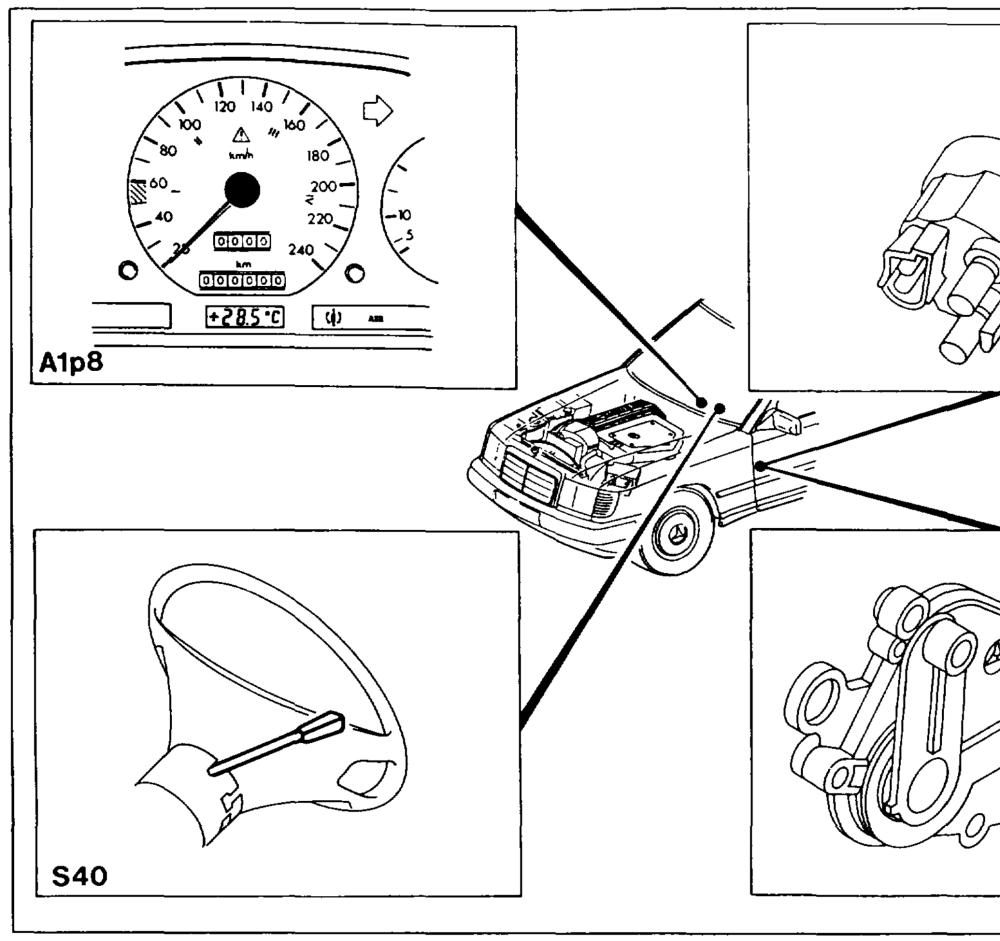
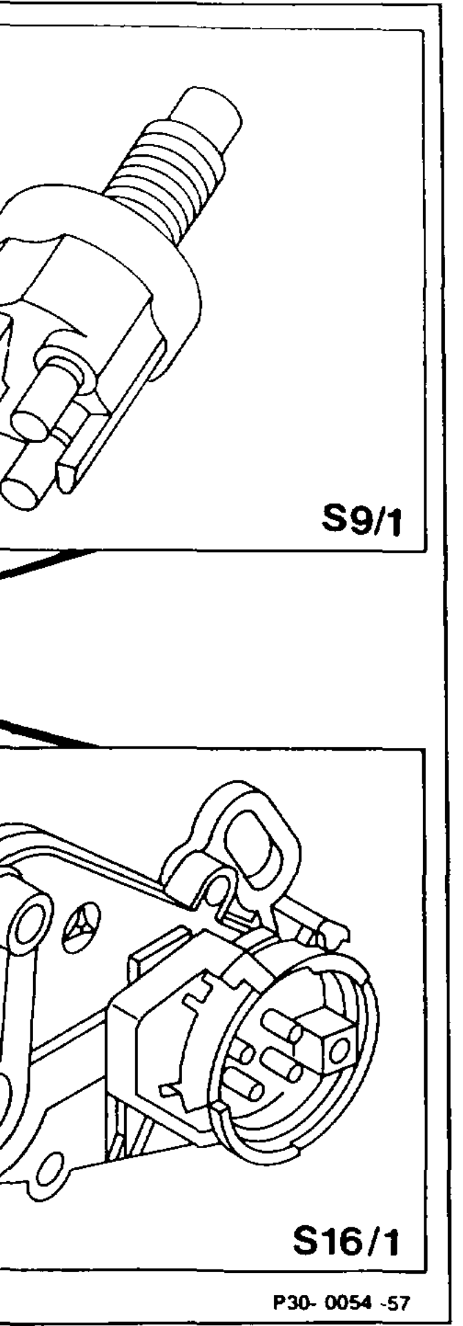
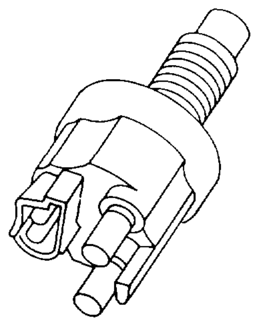
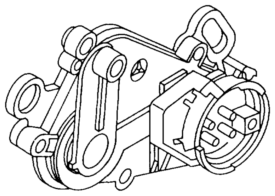
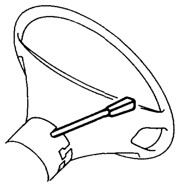
Model 124 Alps Electronic speedometer S40 Tempomat cruise Control switch ssi 4MATIC/ASD stop fight switch Vv Decelerate/set $16/1 Starter lockout and reversing light switch B Accelerate/set SP Memory A Off
whims §=RA 30.1142-1050/2
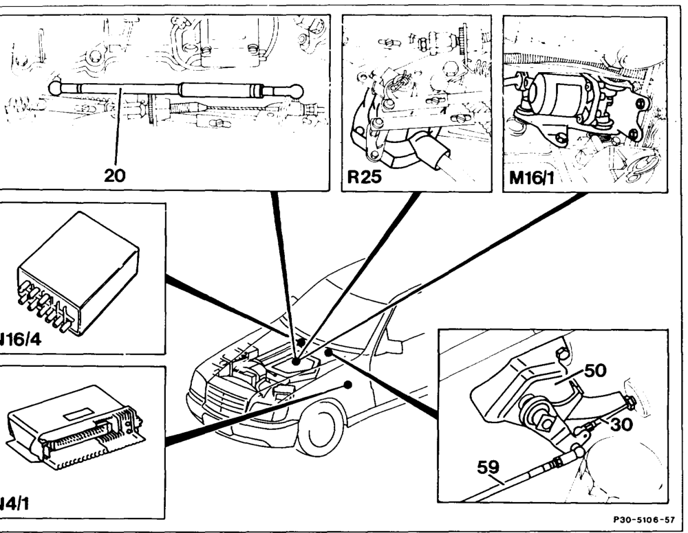
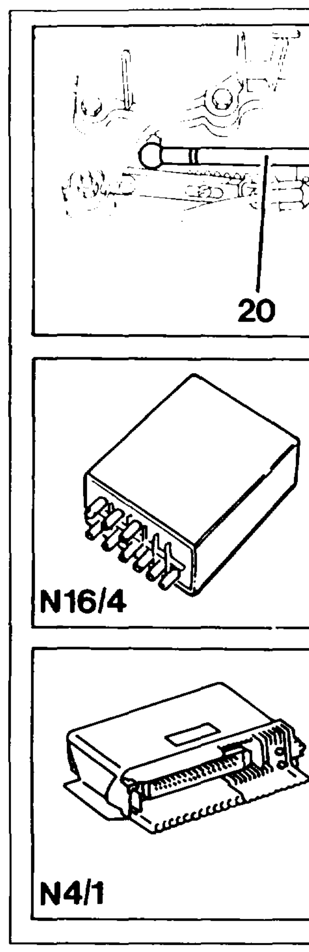
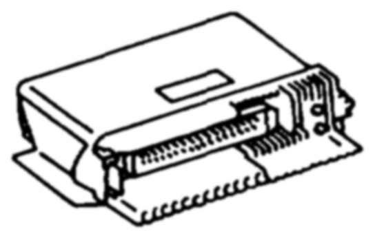
Model 126 Idle travel rod (redundancy rod) 20 M16/1 Electronic accelerator pedal (EFP) actuator Bowden cable (RHD, onty models 126.024/025) N41 Electronic accelerator pedal (EFP) in left footwell Fire wall bearing (RHD, onty models N16/4 Fue! pump relay kickdown shutoff 50 126.024/025) R25 Electronic accelerator pedal (EFP) position Connecting rod (RHD, only models 126.024/025) sensor
oie §=RA 30.1142-1050/3
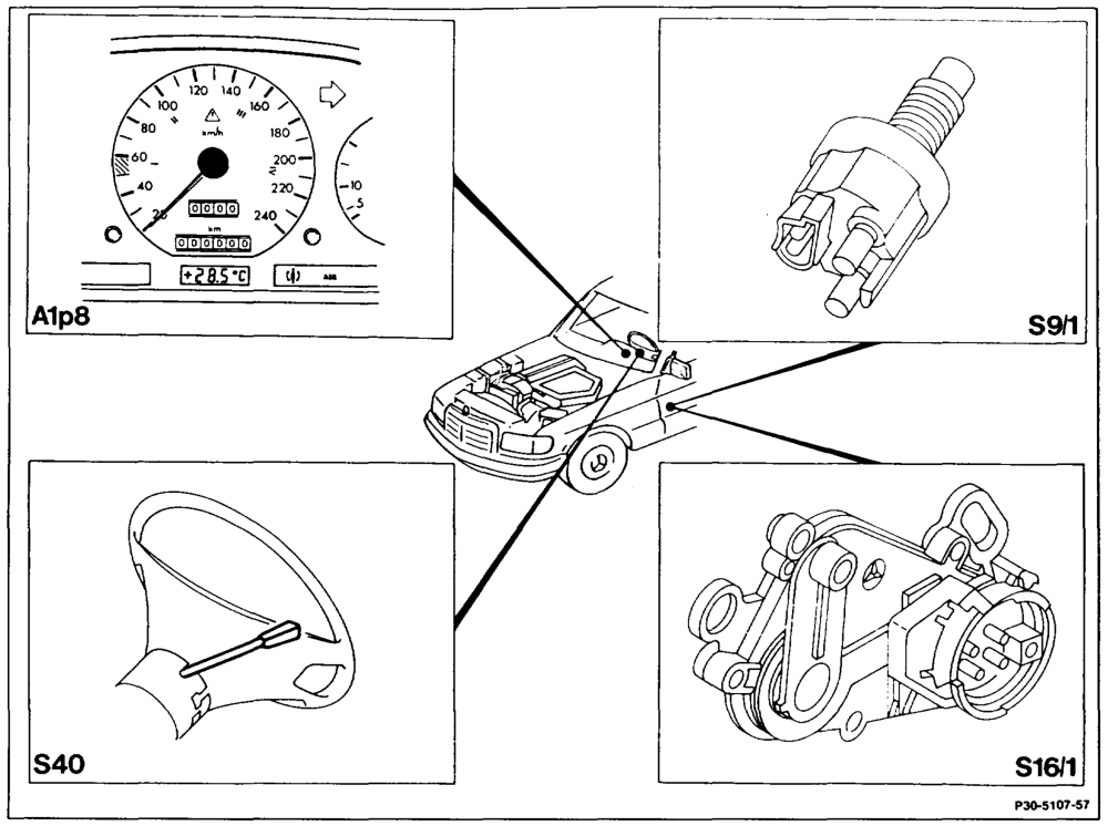
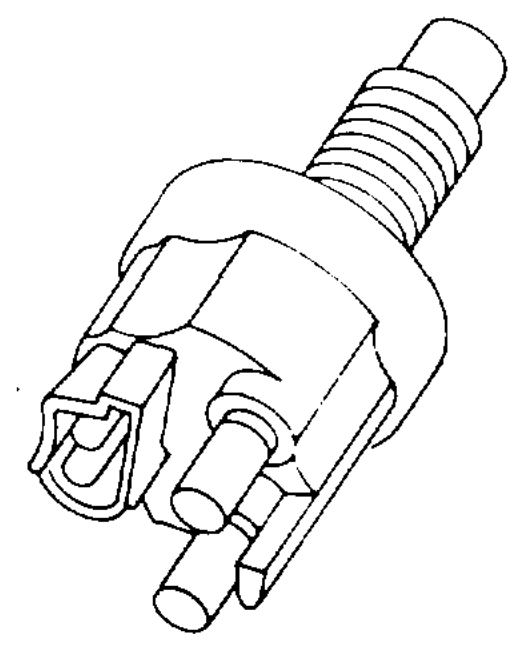
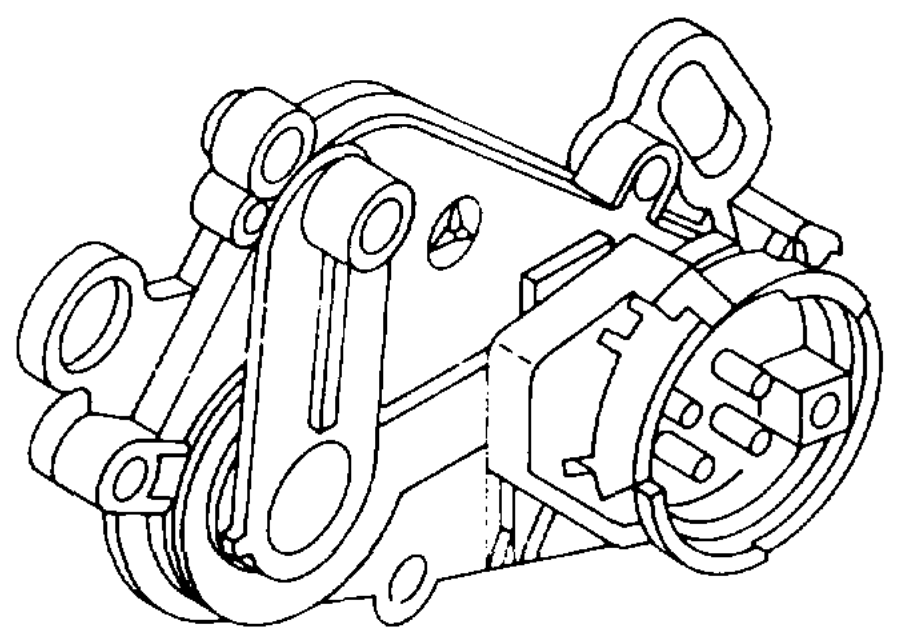
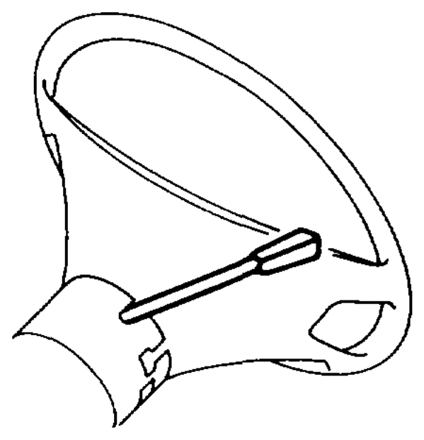
Model 126 A1ps Electronic speedometer $40 Tempomat cruise control switch sot 4MATIC/ASD stop light switch Vv Decelerate/set S16/1 Starter lockout and reversing light switch B Accelerate/set SP Memory A Off
wie §=RA 30.1142-1050/4
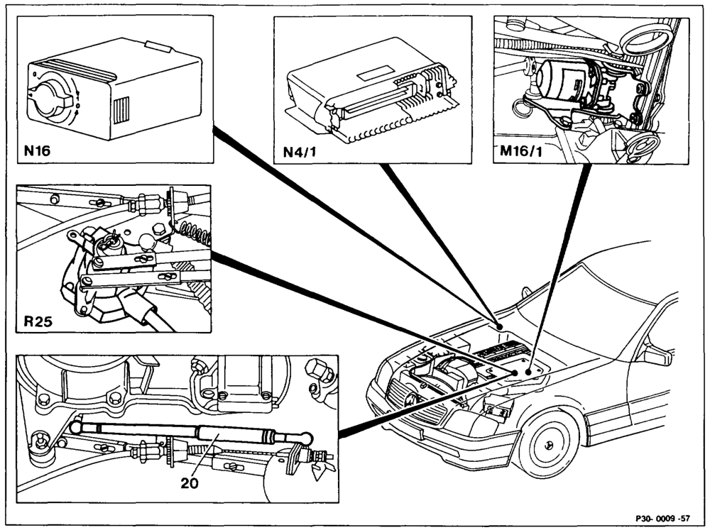
Model 129 Electronic accelerator pedal (EFP) position M16/1 Electronic accelerator pedal (EFP) actuator R25 N4/1 Electronic accelerator pedal (EFP) control unit sensor Idle travel rod (redundancy rod) Engine systems control unit MAS 20 N16
wiime §=RA 30.1142-1050/5

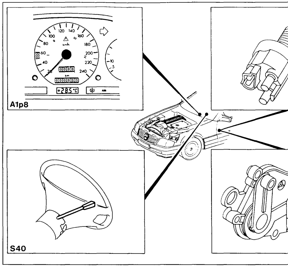
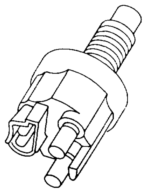
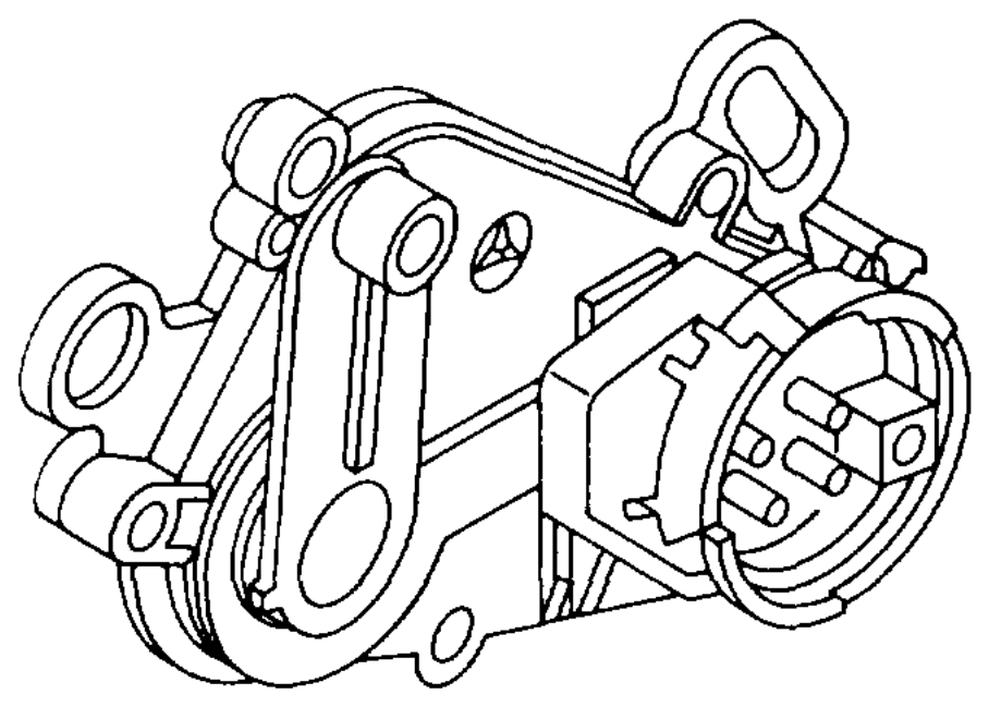
Model 129 Alps Electronic speedometer S40 Tempomat cruise control switch soi ASD/ASR stop light switch Vv Decelerate/set S16/1 Starter lockout and reversing light switch B Accelerate/set SP Memory A Off
wiime §=RA 30.1142-1050/6
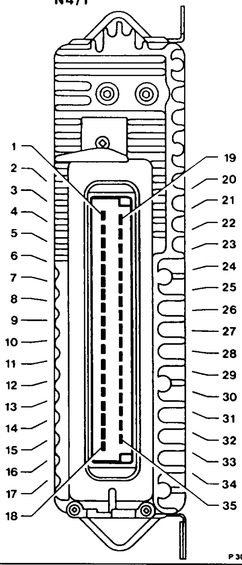
Contact assignment at electronic accelerator N4/1 pedal control unit
Voltage supply terminal 15 unfused a AOnrwn Voltage supply terminal 15 untused Electronic accelerator pedal actuator (engine) Electronic accelerator pedal actuator (engine) Position sensor potentiometer (ground) Actuator, electonic accelerator pedal potentiometer (ground)
7 Do not create contact! 8 _Idle switching signal to KE conwol unit (N3) Position sensor potentiometer voltage supply (+)
10 Not assigned 11. Battery ground (W10)
12 Electronic speedometer, road speed signal
13 Safety switch position sensor
14 Stop light switch
15 Position sensor potentiometer (wiper signal)
16 Tempomat cruise contro! switch (decelerate/set) 17 “Not assigned
18 Tempomat cruise control switch (memory)
19 Do not create contact! 20 —_ Electronic accelerator pedal actuator (engine)
21 Electronic accelerator peda! actuator (engine)
22 Battery ground (W10)
23 Battery ground (W10)
24 Not assigned 25 —_ Not assigned
26 Actuator, electronic accelerator pedal potentiometer (voltage supply) 27 ~—sCNoot assigned
28 Actuator, electronic accelerator pedal potentiometer (wiper signal) P30-0017-17
29 Electronic accelerator pedal actuator (safety switch)
30 Fuel pump relay terminal 15, contact 9 or engine systems control unit terminal 15u, contact 10
31 To ABS/ASR control unit (throttle valve actual value) 32 = Tempomat cruise contro! switch (accelerate/set) 33 — Starter lockout and reversing light switch, Drive mode „R”
34 From ABS/ASR control unit (throttle valve set value)
35 Tempomat cruise control switch (OFF)
wie RA 30.1142-1050/7
P30-0019-53A
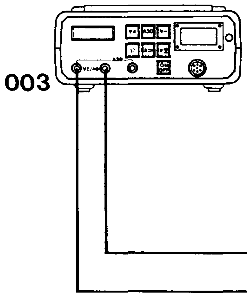
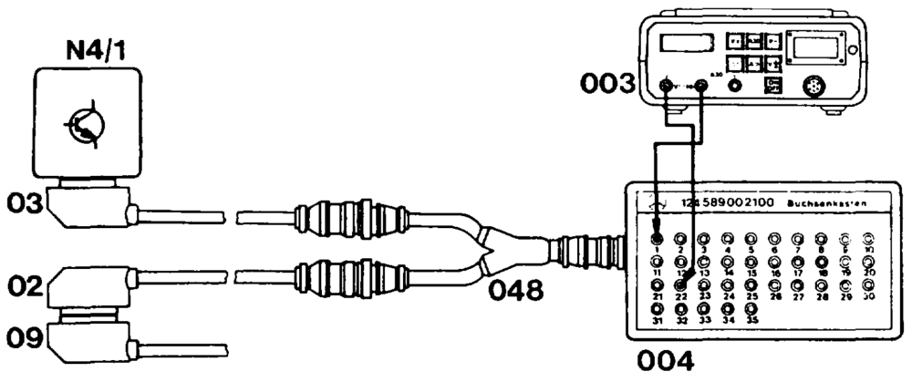
Connection diagram with multimeter for electronic accelerator pedal test program
02
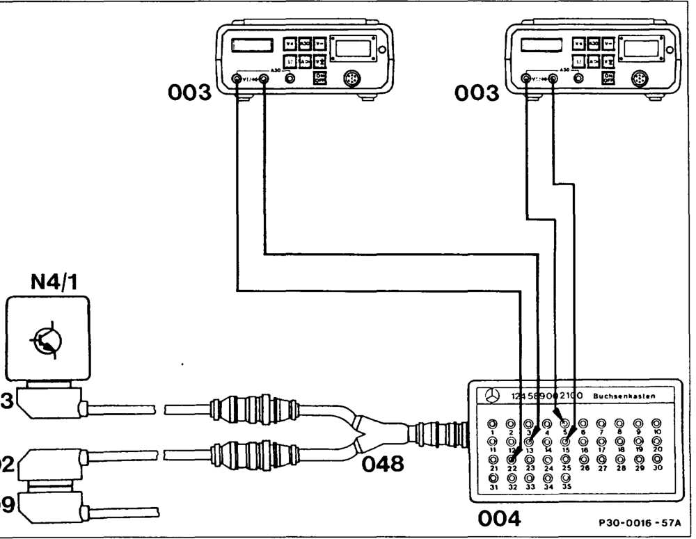
Connection diagram with 2 multimeters for electronic accelerator pedal test program
02 Test cable 645 589 02 63 00 003 Multimeter
03 Test cable 645 589 01 63 00 004 Contact box 35-pin
09 Vehicle cable harness (electronic accelerator 048 Test cable 645 589 00 63 00 pedal control unit) N4/1 Electronic accelerator pedal (EFP) control unit
wie RA 30.1142-1050/8
Special tools
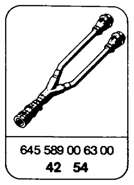
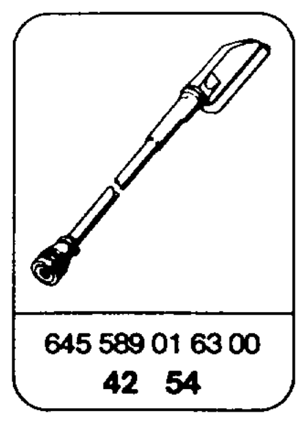
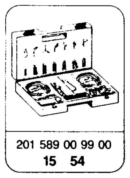
vo
\ ee Ne DD – 124 589 00 21 00
Commercially available tools and testers (see Workshop Equipment Manual) Designation e.g. Make, order no. Multimeter Sun, OMM-5 Frequency generator Sun, DTR 8416
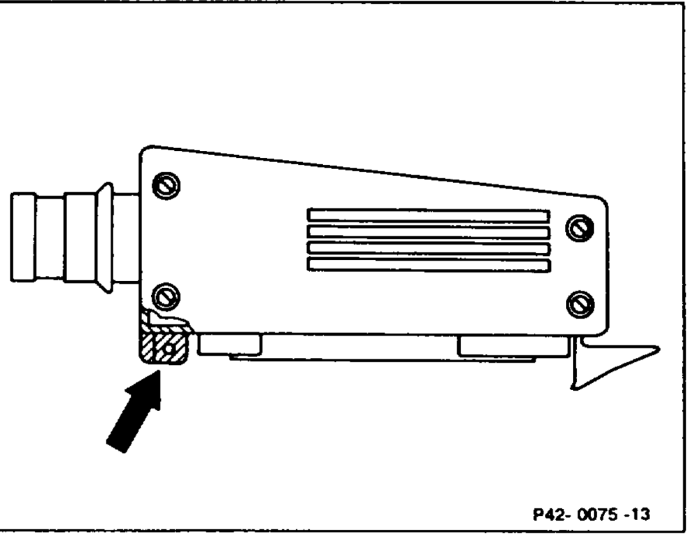
The stud (arrow) on the test cable 645 589 02 63 00 must be sawn off.
wim RA 30.1142-1050/9
Symbols for testers Symbols for test mode with multimeter
=@*+ Function generator, square-wave 35-pin contact box —— Connector signal shape =@)* Multimeter resistance mode — Contact =@®*+ — Multimeter DC voltage mode ==} Bridge
Preconditions for test
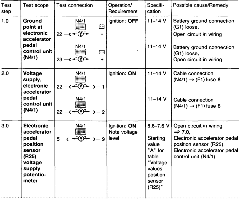
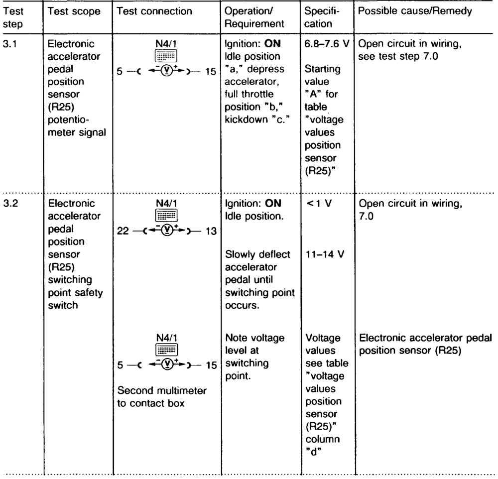
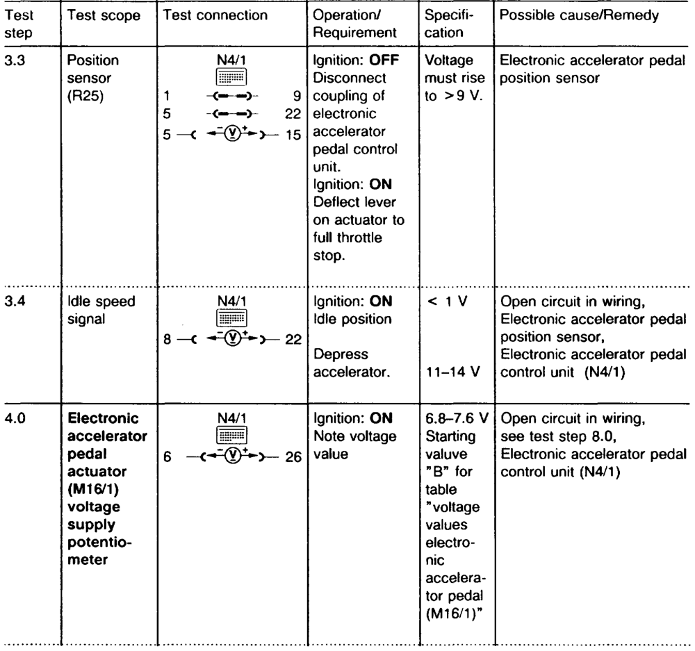
Note e Accelerator control linkage correctly set and If the specification of a main test step, e.g. test check for ease of movement (30-1010). step 3.0, is in order, continue with the next e Battery voltage 11–14 V. main test step, e.g. test step 4.0. If the specification in the main test step, e.g. test step 3.0, is not achieved, continue test with sub-test step, e.g. test step 3.1.
See appropriate wiring diagram volume for wiring diagrams.
wile §=RA 30.1142-1050/10
wii =RA 30.1142-1050/11
wie RA 30.1142-1050/12
ie §=RA 30.1142-1050/13
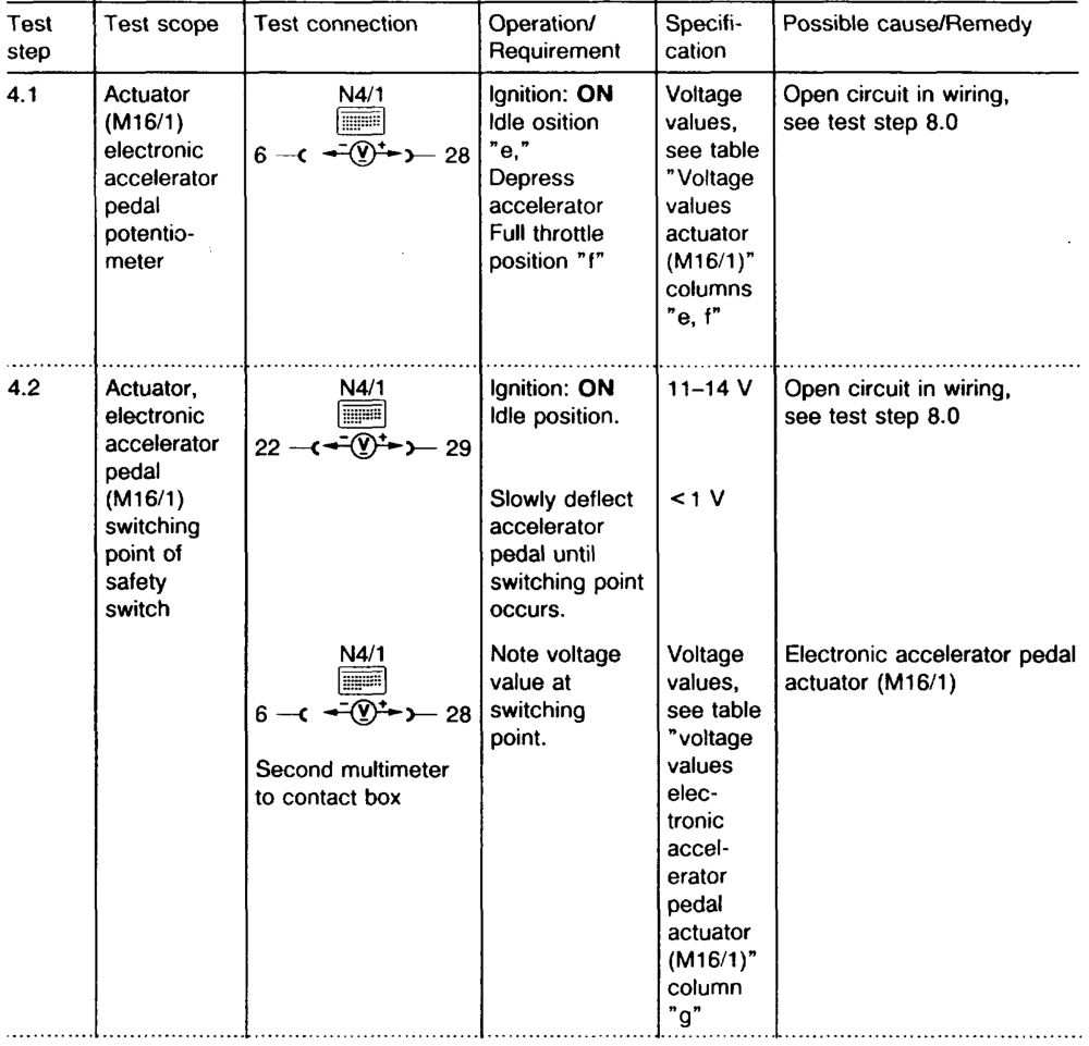
ie = RA 30.1142-1050/14
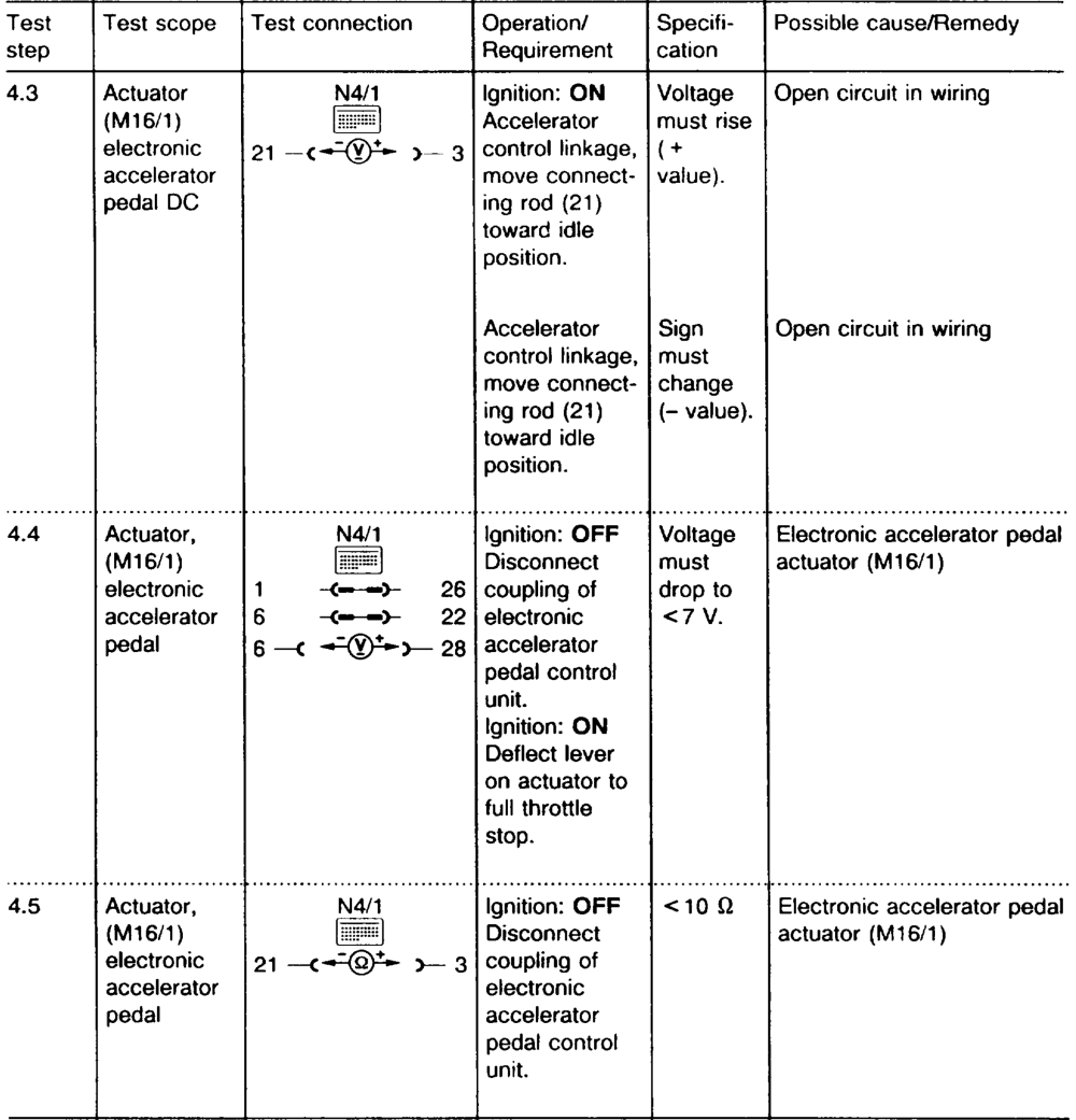
wii RA 30.1142-1050/15
| Test | Test connection | Possible cause/Remedy |
| step | Requirement cation | |

5.0 N41 ON Electronic accelerator pedal lever actuator (M16/1) ”P.” 22 —( 33
Open circuit in wiring lever ”R.”
throttle Electronic accelerator pedal control unit (N4/1) lever to ”R”
N4/1 Open circuit in wiring 6.0
start
22 —=@)*+>— 30 or AN test Contact 30 is not short
unit
Circuit proof to ground, 02 63 Y Electronic accelerator pedal 129 control unit (N4/1), Check whether wiring is correctly connected
OFF test 645 589 00 Y
tie =RA 30.1142-1050/16
| Test | Test scope | Specifi- | Possible cause/Remedy | |
| step | Requirement | cation | ||
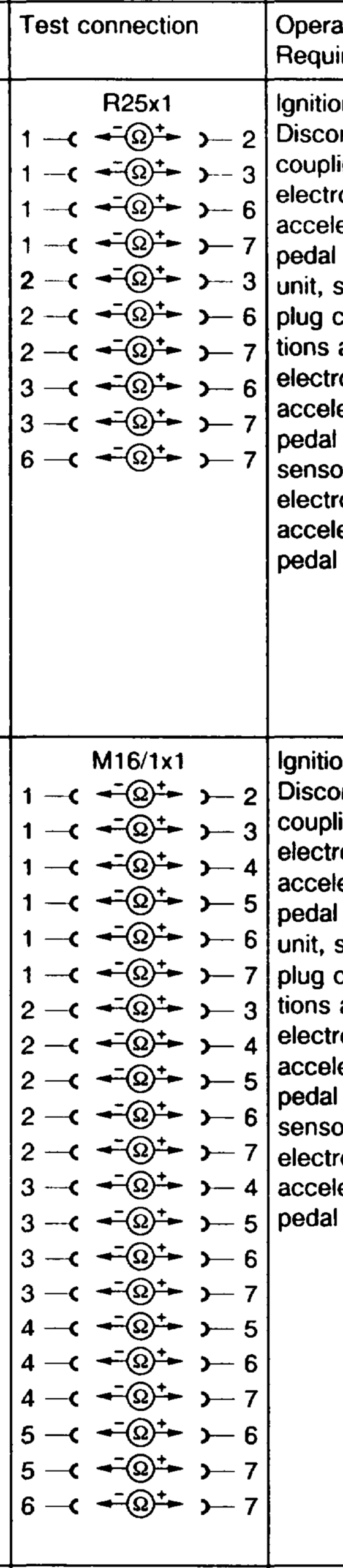
>500 kQ Test OFF if <500 kQ replace wiring 7.0 insulation harness resistance at of cables between plug control connection separate of elecconnectronic at accelerator pedal position sensor position (R25x1) and and coupling of electronic actuator. accelerator pedal control unit (N4/1)
Test OFF >500 kQ. if <500 kQ replace wiring 8.0 insulation harness resistance at of cables between plug control connection separate electronic connecaccelerator at pedal actuator (M16/1) and position coupling of and electronic accelerator pedal actuator. control unit (N4/1)
wiine =RA 30.1142-1050/17
Voitage values electronic accelerator pedal position sensor (R25)
| m AP Voltage supply potentiometer Vv | Voltage at idle position Vv | Voltage at full throttle position Vv | Voltage at kickdown Vv | ng” Voltage at switching point of safety switch Vv |
| 6.8 | 0.50–0.56 | §.92–5.98 | §.92–6.37 | 0.86–1.13 |
| 6.9 | 0.51–0.57 | 6.00–6.07 | 6.00–6.46 | 0.87–1.14 |
| 7.0 | 0.52–0.58 | 6.09–6.16 | 6.09–6.55 | 0.89–1.16 |
| 7.1 | 0.53–0.58 | 6.18–6.25 | 6.18–6.64 | 0.90–1.17 |
| 7.2 | 0.53–0.59 | 6.26–6.34 | 6.26–6.74 | 0.91–1.19 |
| 7.3 | 0.54–0.60 | 6.35–6.42 | 6.36–6.83 | 0.92–1.21 |
| 7.4 | 0.55–0.61 | 6.44–6.51 | 6.44–6.92 | 0.94–1.22 |
| 7.5 | 0.56–0.62 | 6.53–6.60 | 6.53–7.01 | 0.95–1.24 |
| 7.6 | 0.56–0.63 | 6.61–6.69 | 6.61–7.11 | 0.96–1.26 |
Voltage values electronic accelerator pedal actuator (M16/1)
| >Br Voltage supply potentiometer Vv | e Voltage at idle position Vv | Voltage at full throttle position Vv | wan Voltage at switching point of safety switch Vv |
| 6.8 | 6.05–6.19 | 0.61–0.75 | 5.35–5.68 |
| 6.9 | 6.14–6.28 | 0.62–0.76 | 5.43–5.76 |
| 7.0 | 6.23–6.37 | 0.63–0.77 | 5.51–5.89 |
| 7.41 | 6.32–0.46 | 0.64–0.78 | 5.59–5.93 |
| 7.2 | 6.41–6.55 | 0.65–0.79 | 5.67–6.01 |
| 7.3 | 6.50–6.64 | 0.66–0.80 | 5.75–6.10 |
| 7.4 | 6.59–6.73 | 0.67–0.81 | 5.82–6.18 |
| 7.5 | 6.68–6.83 | 0.68–0.83 | 5.90–6.26 |
| 7.6 | 6.76–6.92 | 0.69–0.84 | 5.98–6.35 |
wie §=RA 30.1142-1050/18
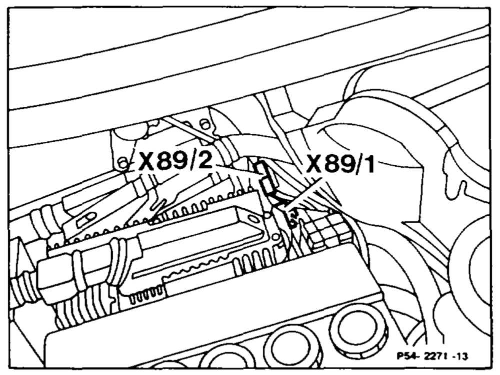
Location of plug connection
Model 124 X89/1 Plug connection, electronic accelerator pedal (EFP) control univASR 2-pin X89/2 Plug connection, electronic accelerator pedal (EFP) control unit/engine wiring harness, 3-pin
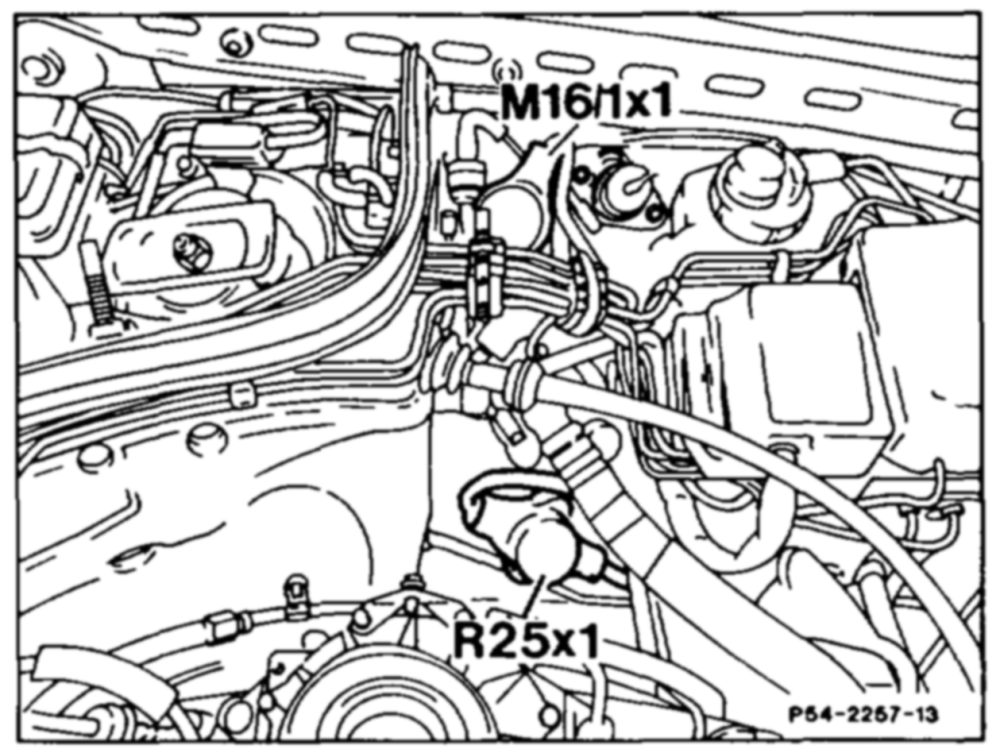
Model 124 M16/1×1 Plug connection, electronic accelerator pedal (EFP) actuator R25x1_—- Plug connection, electronic accelerator pedal (EFP) position sensor
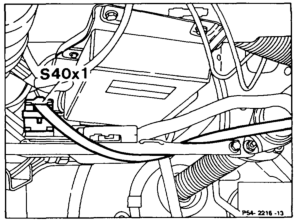
Model 124 $40×1 Plug connection, Tempomat Cruise control (TPM) pushbutton
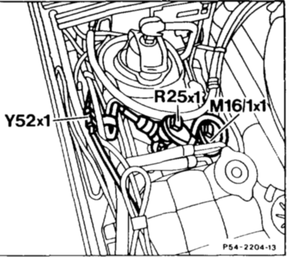
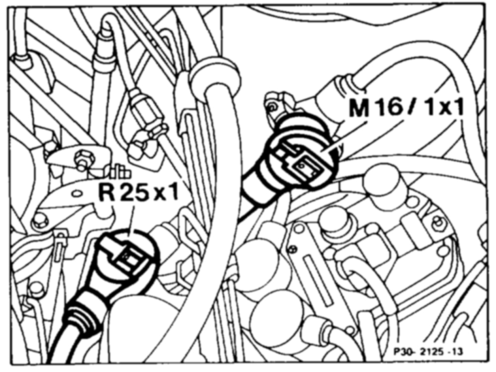
Model 129 M16/1×1 Plug connection, electronic accelerator pedal (EFP) actuator R25x1_—- Plug connection, electronic accelerator pedal (EFP) position sensor Y52x1__—- Plug conection, right front axle damper valve
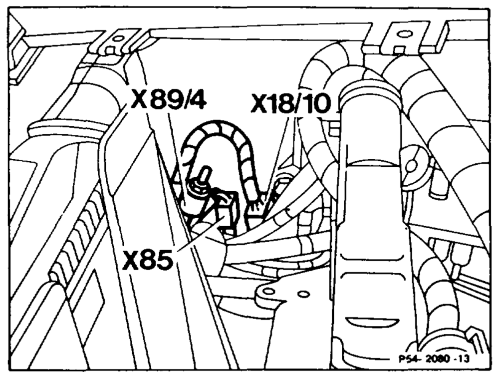
Model 129 X18/10 = Interior/ASR plug connection, 8-pin X85 Plug connection, heater and automatic temperature control (HAU, TAU)/engine wiring harness, 4-pin X89/4 Plug connection, electronic accelerator pedal (EFP) control UNniVKE, 1-pin
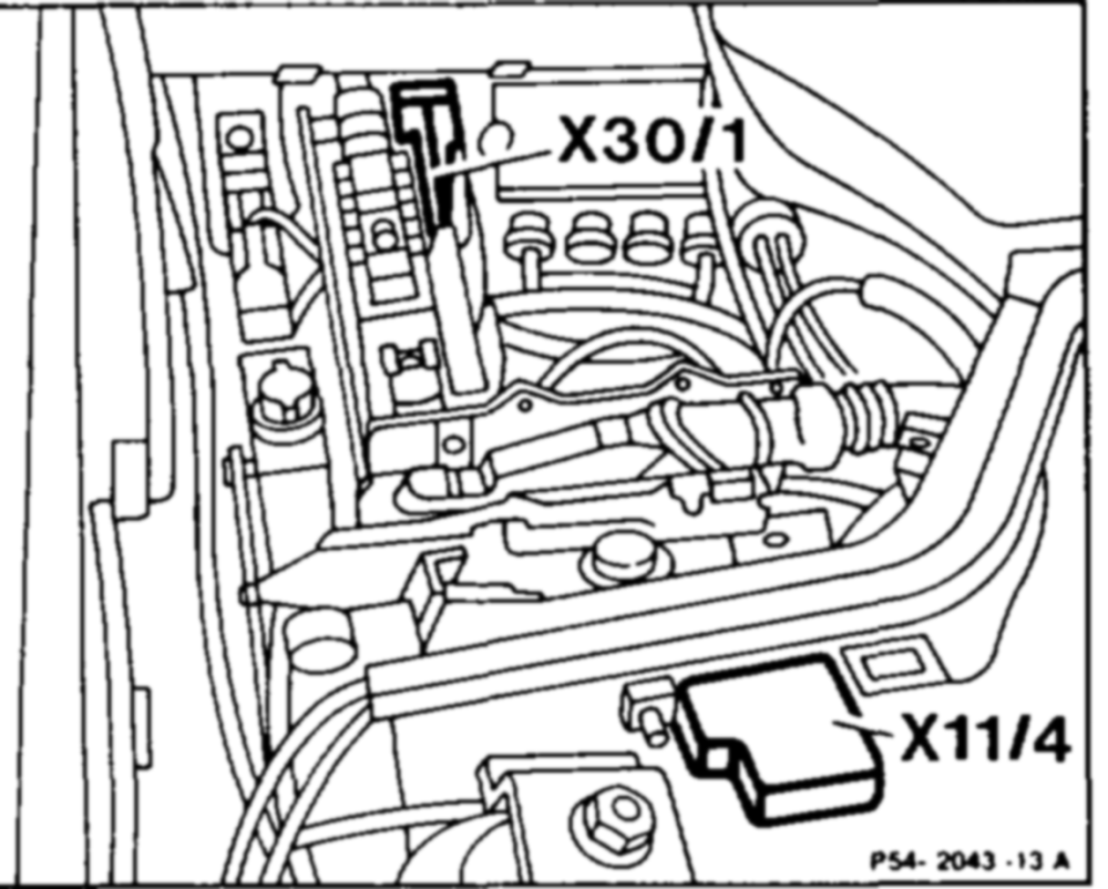
Model 129 X11/4 Test coupling for diagnosis, 16-pin (pulse signal) X30/1 Plug connecction, multi-function block
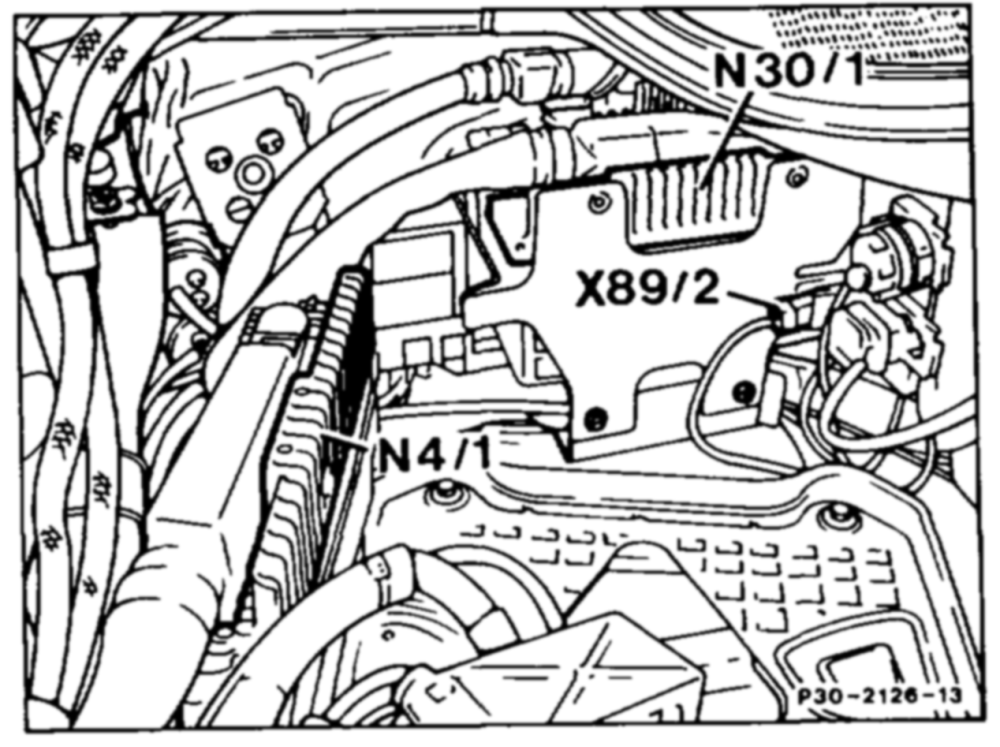
Model 201 X89/2 Plug connection, electronic accelerator pedal (EFP) control uniVengine wiring harness, 2-pin
Model 201 M16/1x1_ Plug connection, electronic accelerator pedal (EFP) actuator R25x1_——- Plug connection, electronic accelerator pedal (EFP) position sensor
etme RA 30.1142-1050/20
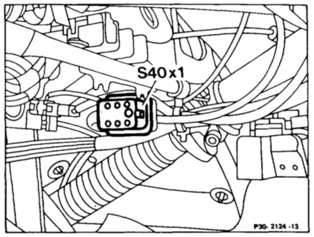
Model 201 $40x1_ Plug connection, Tempomat Cruise control (TPM) pushbutton
wie = RA 30.1142-1050/21