Testing starting valve actuation
WIS 07.3-1607
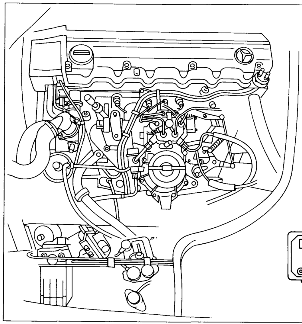
Operation no. of operation texts and work units or standard texts Preceding work: Testing starting device (07.3-2353). and flat rates: 07-1607.
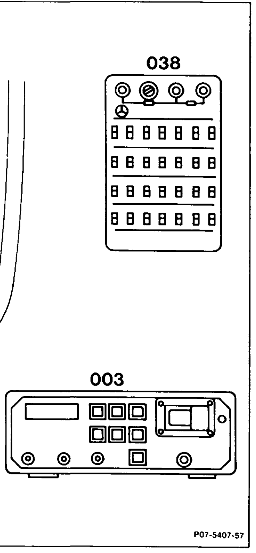
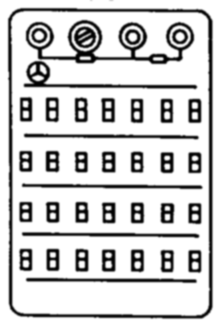
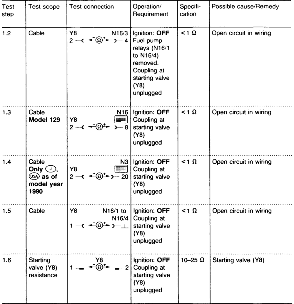
Testers connect: multimeter (003), ohms decade (038) 124 589 09 63 00. Starting voltage test. Minimum 10 V in approx. 5 seconds. Electric wiring 0.0.00… cee eee eee between starting valve and fuel pump relay, test for continuity. Resistance approx. 0 2. Voltage at fuel pump relay and engine systems control unit 2.2… ee ee eee eee test. Contact 12 (terminal 50) at least 10 V, contact 2 (terminal TF) 3–5 V simulated at 10 kQ.
wii §=RA 07.3.1112-1607/1
Lambda tester ……………….2.006connect to diagnostic socket (X11). Ignition 2.0… ee eee eee switch on. Readout 70% or for California 85%. Coolant temperature sensor (B11/2) coupling … unplug. Readout 30%. At coolant temperature (B11/2) coupling ……. simulate 10 kQ with Q decade, connect diagonally into circuit, until lambda tester indicates 70% or for California 85%. Protective connector part no. 102 589 02 2100 . plug into diagnostic socket.
Special tools
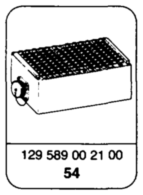
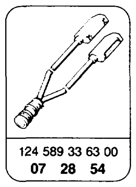
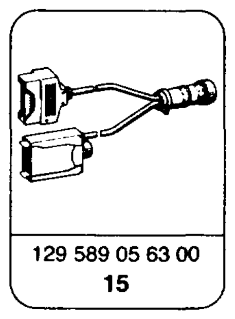
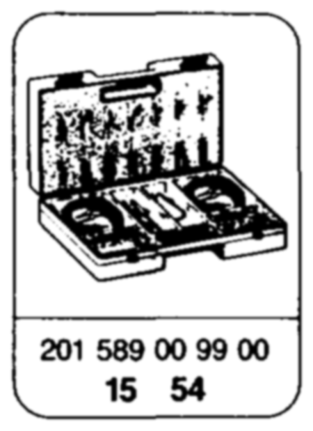
Commercially available tools and testers (see Workshop Equipment Manual) Designation e.g. Make, order no. Multimeter Sun, DMM-5
wim RA 07.3.1112-1607/2
Symbols for testers Symbols for test mode with multimeter
Multimeter =@Y*+ Multimeter Contact box DC voltage mode – Connector =@*+ — Multimeter — Contact Resistance mode a Ground
Test condition Note
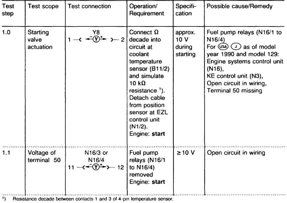
Battery voltage 11–14 V If the specification e.g. of point 1.0 is in order, it is not necessary to perform test step 1.1. See appropriate wiring diagrams volume for wiring diagrams.
wim = RA 07.3.1112-1607/3
tie =RA 07.3.1112-1607/4
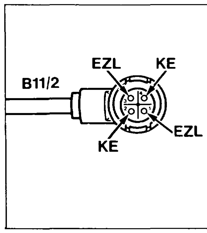
Coolant temperature sensor coupling, 4-pin
Coupling pin assignment 1 EZU/AKR temperature sensor 2 KE temperature sensor 3. Ground, EZU/AKR ignition control unit 4 — Ground, KE ignition control unit ?07-2022–13
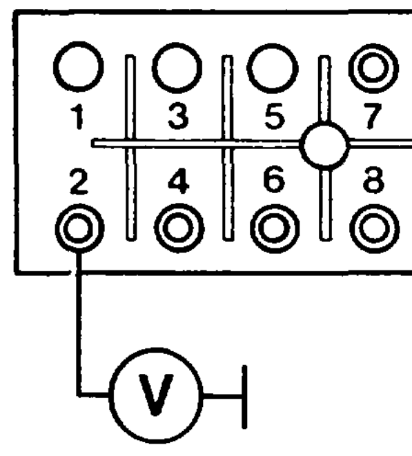
Fuel pump relay test connection
Socket 12/socket 2
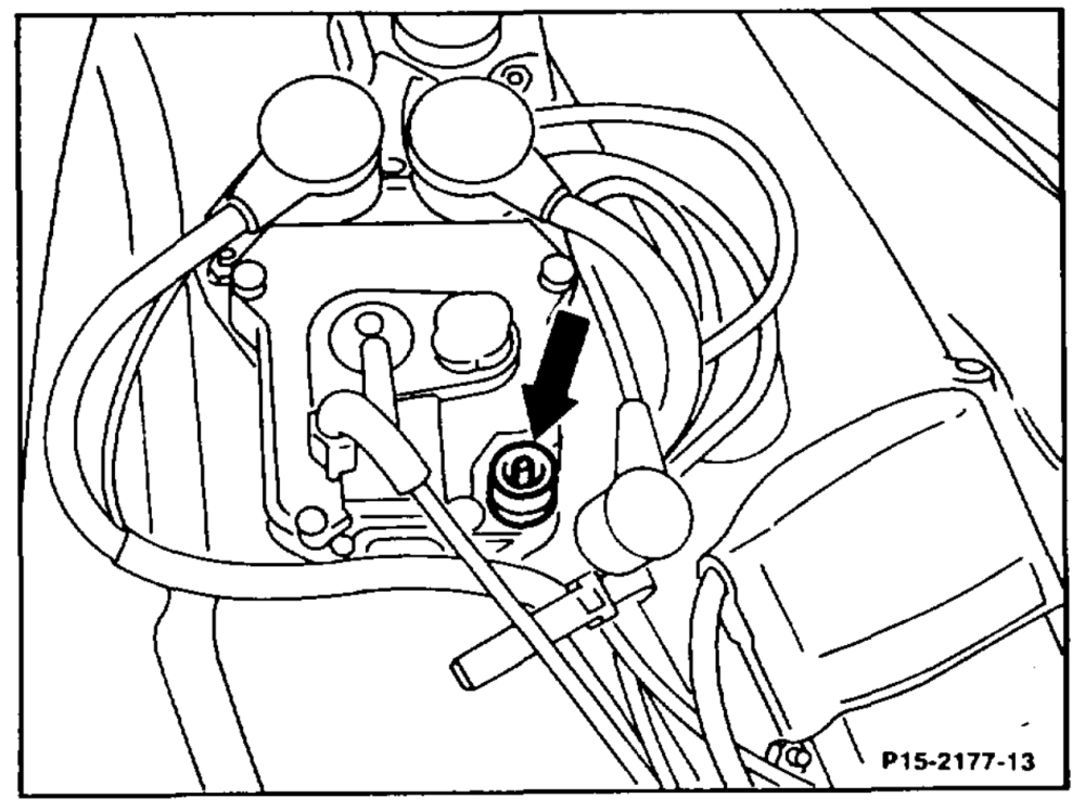
Arrangement of EZL control unit position sensor