Testing, adjusting engine
WIS 07.3-1100
Operation no. of operation texts and work units of standard texts and flat rates: 07-1100.
Basic and national versions
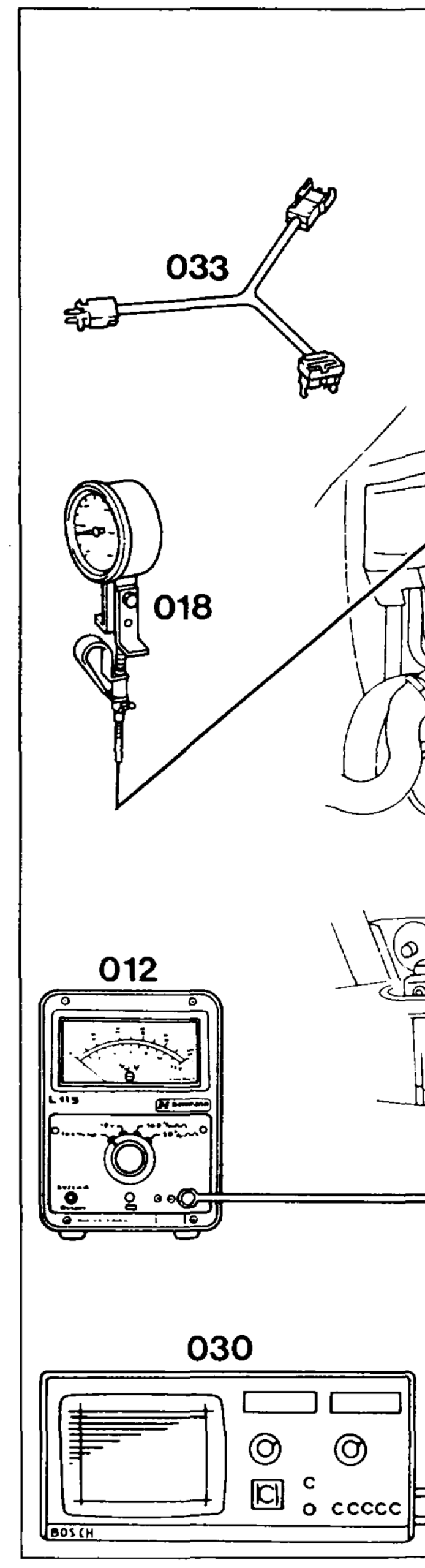
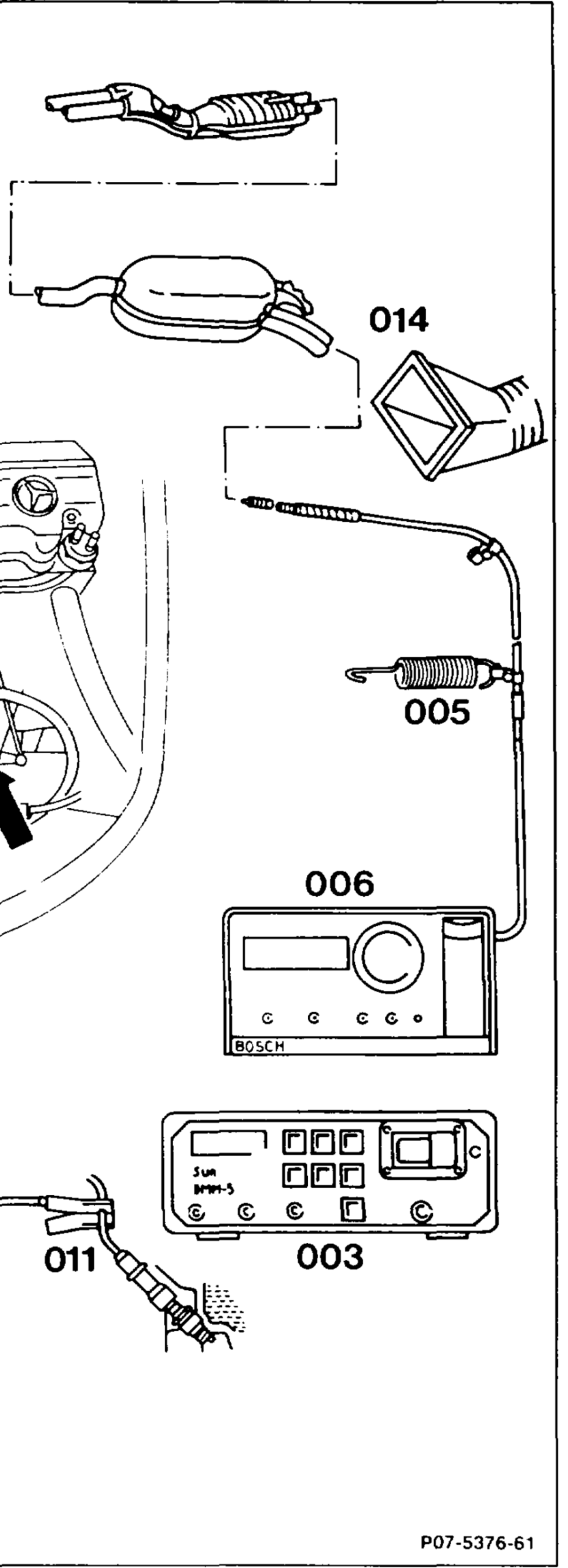
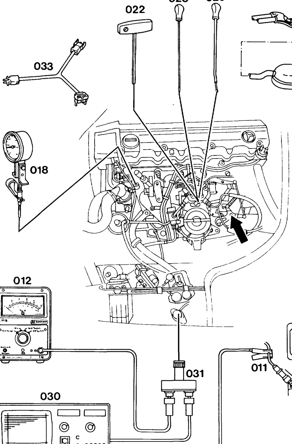
028 029
wii = RA 07.3.1112-1100/1
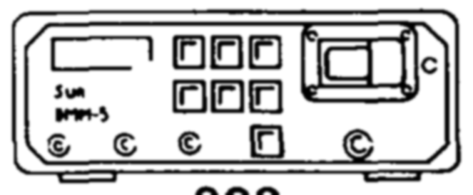
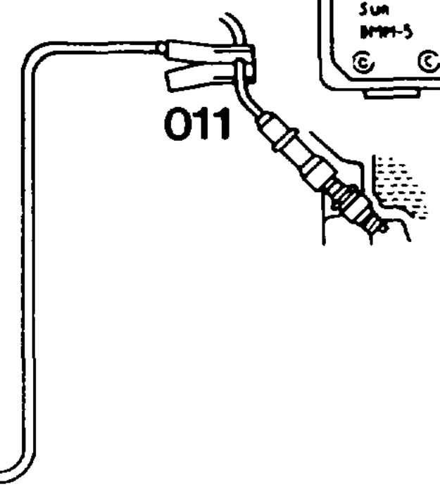
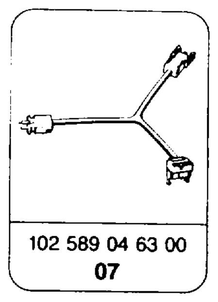
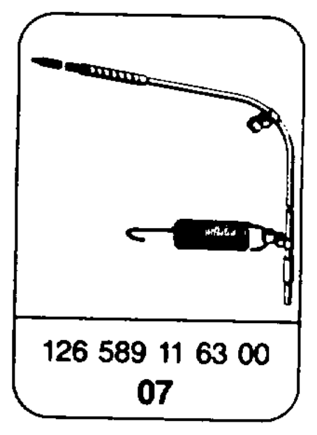
Test sheet ……………….2….000-. complete. A/C or automatic climate control switch off. Selector lever… 20… 2.2.00… eee ee eee move into position ”P.” TesterS 2… ke ee connect: oil remote thermometer (018) 124 589 07 21 00, lambda control tester (012), twin socket (031), exhaust probe (005) 126 589 11 63 00, CO analyzer (006), engine tester with oscilloscope (030), trigger clamp (011), multimeter (003), test cable (033) 102 589 04 63 00. Extraction device (014) ……………20045 position at exhaust tailpipe. Coolant level ………….2.000 002 eee ee check, adjust to correct level. Engine oil level …………….0..0000 008 check, pay attention to condition of oil (visual check). Air cleaner 2.2… 2… cee ee ee eee remove, install. Accelerator control linkage (arrow) and throttle valve 6.2 ee eee eee check ease of movement and condition. Grease bearing points, relay levers, ball sockets. Idle Stop we ee ee eee check. Fulcrum lever 20… 0.0000. check, adjust. Full throttle stop ………..-….-.2-006% check from accelerator pedal, adjust. VoltageS 2… eee ee test at battery and ignition coil terminal and 15. Current at actuator 0.0. .02008test with ignition switched on. Ignition timing ………….0 2000 e ee eee ee test, adjust (see table). Vacuum advance …………-0002 eee eee test, adjust (see table). Oil level in automatic transmission ……….. check, adjust to correct level. Engine oil level …………….-.2220008approx. 80°C. Oscilloscope image ……………-..0006analyze. Intake system 0.00. eee eee ee eee check for leaks by spraying.
wii =RA 07.3.1112-1100/2
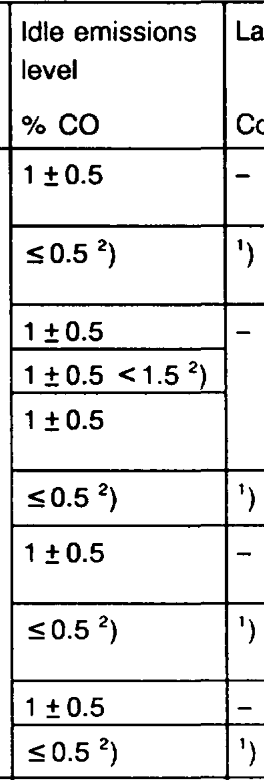
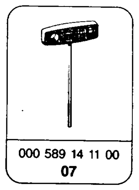
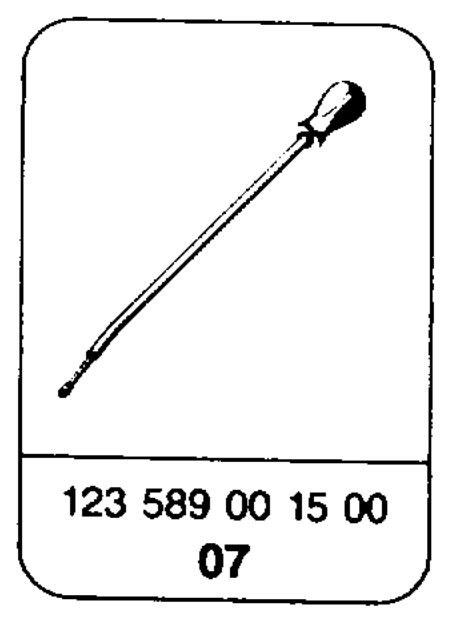
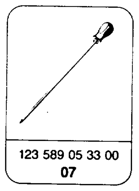
Functional check of electrical components …. – perform. Exhaust gas recirculation valve …………-. test. Idle speed 2… eee ee ee ee eee check (see table). Idle emissions level or lambda control ……… test, adjust (see table). For adjusting use special tools screwdriver (022) 000 589 14 11 00, puller (028) 123 589 05 33 00, insertion drift (029) 123 589 00 15 00. Smooth engine running ……………-5– check. Switch on all ancillaries for this step.
Test and adjustment data
Basic version
Engine Idle speed Lambda control
1/min Control range Control range % 103.940 650-750 35~45% 103.941 21–27° A
103.943
103.980 600-700
103.981
103.982 up to 5/90: 103.983 600-700 103.985 as of 6/90:
103.984 650-750
1) Test lambda control at 2500/min and read off mean value. Detach regeneration line at regeneration valve for this step and seal. Compare this reading with idle emissions reading. The mean value at idle speed must not differ by more than +10 from the reading obtained at 2500/min. 2) For special emissions test (ASU).
wii §=RA 07.3.1112-1100/3
National version 1986-1991 silver information plate
| Engine | Version | Idle speed 1/min | Control range | Idle emissions — Lambda control level % CO | Control range % |
| 103.94 103.98 | 700 +50 650 +50 | 35–45% (21–27° A | – | ) |
1) Test lambda control at 2500/min and read off mean value. Detach regeneration line at regeneration vaive tor this step and seaj. Compare this reading with idle emissions reading. The mean value at idle speed must not differ by more than + 10 from the reading obtained at 2500/min.
National version up to 1986 green information plate
4) 1986, 1987 green information plate CD KAT 1986, 1987 light green information plate @ KAT as of 1988 information plate not fitted, engine data setting plate instead 1986, 1987 blue information plate
CS KAT as of 1986 light blue information plate
| Engine | Version | Idle speed 1/min | Control range | Idle emissions level % CO | Lambda control Control range % | ||
| 103.94 | CH) KAT Cs) KAT | 700+50 | 35–45% 21–27° 4 | <0.5 | 5» | ||
| 103.98 auBer | DCS) | 780450 | 0.6+0.3 | – | |||
| 103.984 | KAT KAT | 650+50; as of 06/90 750 + 50 | <0.5 | ) | |||
| 103.984 | KAT KAT | 700 +50 | |||||
| 1) National version C2) 1986-1990 information plate in Japanese | Test lambda contro! at 2500/min and read off mean value. Detach regeneration line at regeneration valve for this step and seal. Compare this reading with idle emissions reading. The mean value at idle speed must not differ by more than +10 from the reading obtained at 2500/min. | ||||||
| Engine | Version | Idle speed d/min | Control range | Idle emissions — Lambda control level % CO | Control range % | ||
| 103.94 103.98 | © | 700 +50 650 +50 | 35–45% | – | |||
1) Test lambda control at 2500/min and read off mean value. Detach regeneration line at regeneration vaive for this step and seal. Compare this reading with idle emissions reading. The mean value at idle speed must not differ by more than + 10 from the reading obtained at 2500/min.
wile =RA 07.3.1112-1100/4
National version sa) 1986-1989 black information plate 1990 black information plate Federal, yellow California Engine Version Idle speed Idle emissions Lambda control level
1/min Control range % CO Control range % 103.94 700 +50 35–45% – ’) 103.98 650 + 50; as of model year 1990 700 +50 1) Test lambda control at 2500/min and read off mean value. Detach regeneration line at regeneration valve for this step and seal. Compare this reading with idle emissions reading. The mean value at idle speed must not differ by more than +10 from the reading obtained at 2500/min.
Current at actuator
Engine Version Current with ignition switched on (mA)
103.94 KAT 20
103.98
103.94 RUF, without KAT 10
103.98 ’) 1) Engine 103.980 Sid.: 0 mA.
wile =RA 07.3.1112-1100/5
EZL ignition timing point
| Engine EZL ignition | speed | Ignition timing point in ° CA before TDC | ||
| contro} unit | Resistance trimming plug position or type of fuel | without vacuum | with vacuum | |

Basic version KAT/RUF and KAT

103.940 25–29 40–44 103.941 103.942 19–23 103.943 speed 7–11 711
103.980 23–27 39–43 speed 8–13 8–13
= 19–23 39–43 speed 5 43 8–13 103.981 27–31 40–44 103.983 103.985 21–25 40–44 speed 6–11 6–11
103.982
103.984
National version G) 1986, Cs) 1986 1)
103.981 004 545 69 32 3200 Ss 29–33 40–44 103.983 005 545 49 32 005 545 88 32 N 23–27 Idle speed S and N OT +2 OT +2 4) For Cen) KAT, G KAT, same values as basic version KAT.
wile §=RA 07.3.1112-1100/6
EZL ignition timing point
| Engine EZL ignition | Engine speed | Ignition timing point in ° CA before TDC | |
| control unit | 1/min | Resistance trimming plug position or type of fuel | with vacuum |
National version
103.940 005 545 84 32 3200 Reference 40–44 resistor 220 Q 103.942 005 545 86 32 National version 7–11 006 545 73 32 006 545 75 32 008 545 61 32 008 545 63 32
103.981 004 545 44 32 Reference 3200 103.983 resistor 220 Q 004 545 46 32 National version 6–11 005 545 85 32 005 545 87 32 006 545 74 32 006 545 76 32 008 545 62 32 008 545 64 32 National version GC)
103.940 005 545 84 32 Reference 40~44 3200 103.942 resistor 750 2 005 545 86 32 National version 7–11 006 545 73 32 006 545 75 32 008 545 61 32 008 545 63 32
103.981 004 545 44 32 Reference 3200 103.983 resistor 750 Q 004 545 46 32 National version 103.985 005 545 85 32 005 545 87 32 006 545 74 32 _ 006 545 76 32 008 545 62 32 008 545 64 32
National version
103.940 Reference 005 545 84 32 3200 40–44 103.942 resistor 750 Q 005 545 86 32 National version 7–11 006 545 73 32 006 545 75 32 008 545 61 32 008 545 63 32 008 545 95 32 009 545 79 32
103.981 Reference 004 545 44 32 3200 40–44 103.983 004 545 46 32 resistor 750 Q National version 6–11 005 545 85 32 005 545 87 32 006 545 74 32 006 545 76 32 008 545 96 32 009 545 80 32
Special tools
NOT ST
YS Do.
NOT
Commercially available testers (see Workshop Equipment Manual)
| Designation | e.g. Make, order no. |
| CO analyzer | |
| Engine tester (engine speed, dwell angle, ignition angle, oscilloscope, voltmeter) | Bosch, MOT 002.02 Sun, 1019 |
| Lambda control tester | Hermann, L 115 |
| Multimeter | Sun, DMM-5 |
| Twin outlet | Hermann, ECD 53 |
Shop-made tools
Intake pipe DIN 19534 DN 100 for air flow sensor length approx. 500 mm Seal e.g. from air cleaner
wim =RA 07.3.1112-1100/8
Note Test and adjust lambda control with a lambda control tester. If no lambda control tester is available, a dwell angle tester may be used. Idle speed must not be set when the engine is too hot, e.g. immediately after driving sharply or after measuring engine output on the dynamometer.
Testing, adjusting
1 Complete test sheet.
2 Switch air conditioner or automatic climate control.
3 move selector lever into position ”P.”
4 Connect testers: oil remote thermometer (018) 124 589 07 21 00, lambda control tester (012), twin outlet (031), exhaust probe (005) 126 589 11 63 00, CO analyzer (006), engine tester with oscilloscope (030), trigger clamp (011), multimeter (003), test cable (033) 102 589 04 63 00.
wie RA 07.3.1112-1100/9
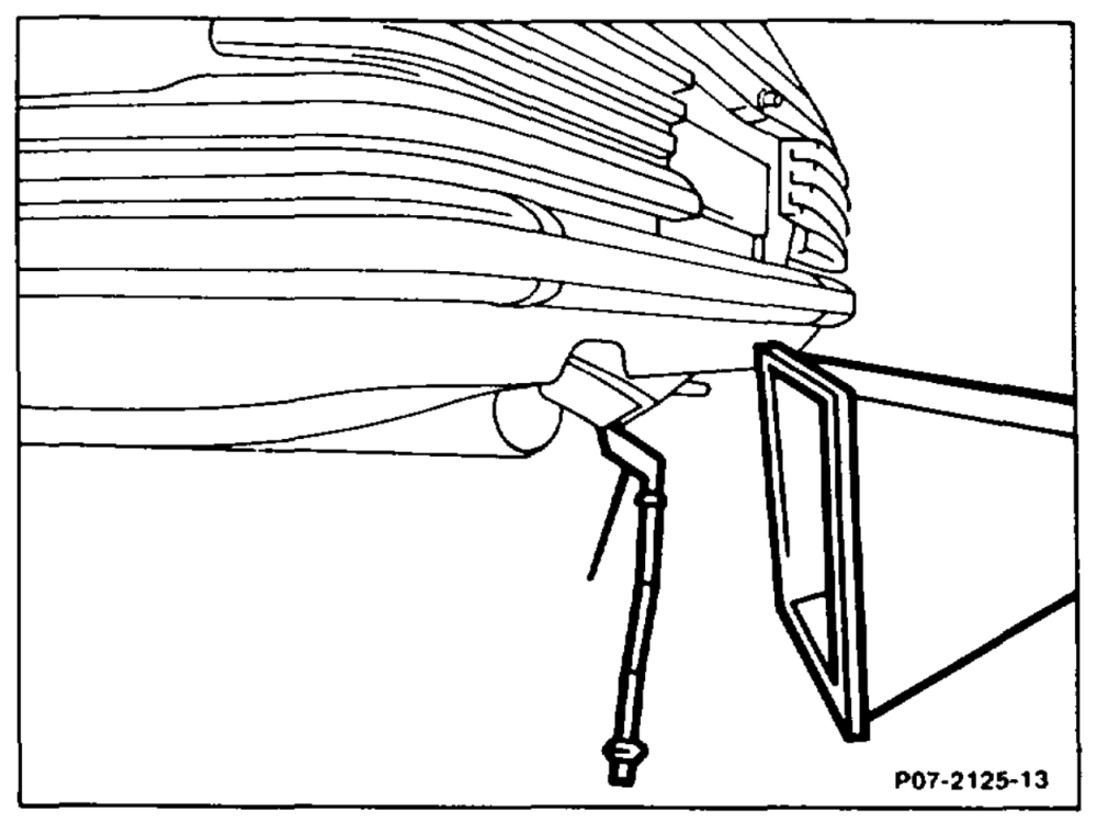
5 Fit extraction device (014) into exhaust tailpipe.
6 Check coolant level, adjust to correct level if necessary.
7 Check engine oil level, paying attention to condition of oi! (visual check).
8 Check oil !evel in automatic transmission.
9 Remove air cleaner (09-1051).
10 Check ease of movement and condition of accelerator control linkage and throttle valve. Lubricate all bearing points and ball sockets.
11 Check idle speed stop.
Engines without ASR
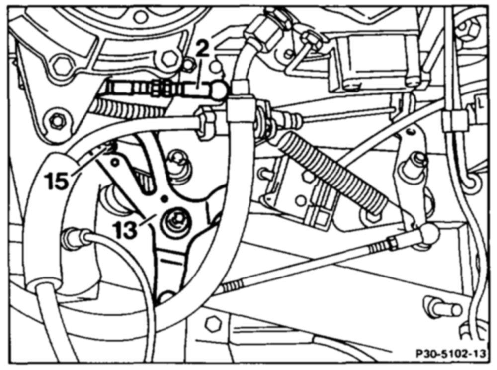
Check fulcrum lever, adjust. Check whether the roller (15) in the fulcrum lever (13) is resting free of testing against end stop. Adjust fulcrum lever (13) if necessary with the connecting rod (2) so that the roller (15) is resting free of tension against end stop.
wim RA 07.3.1112-1100/10
Engines with ASR
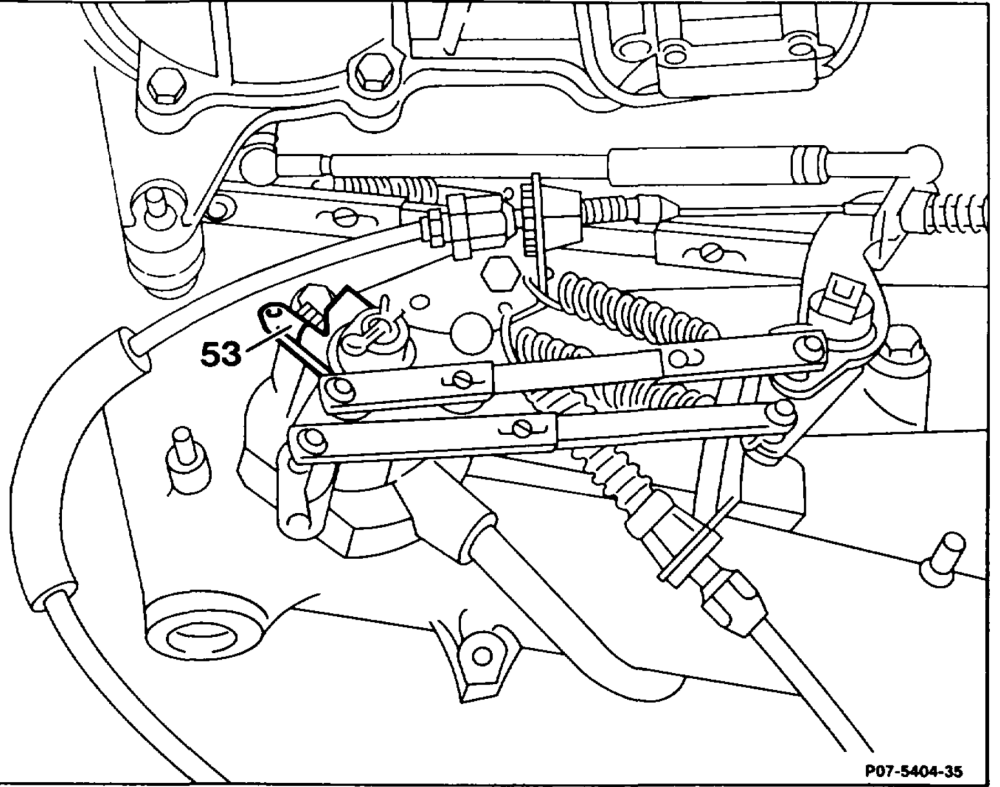
Switch on ignition. Fulcrum lever of set point sensor (53) must be resting against idle speed stop; adjust if necessary (30-1010).
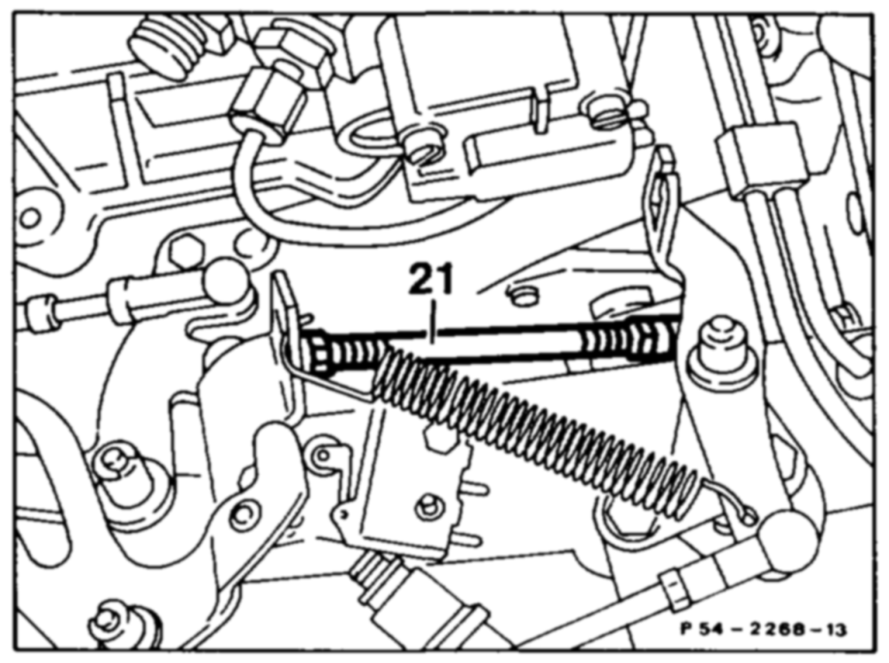
Check whether the throttle valve is resting against idle speed stop. Detach connecting rod for this step.
Vehicles with Tempomat cruise control
Check whether the actuator is resting against idle speed stop of the Tempomat cruise control. To do this, push lever of actuator clockwise against idle speed stop of Tempomat cruise control. When attaching the pull rod (21), ensure that the lever of the actuator is lifted about 1 mm off the idle stop at the cruise control. Adjust pull rod if necessary.
12 Check full throttle stop from accelerator pedal, adjust (30-1010).
wii =RA 07.3.1112-1100/11
a) No-load voltage
Connect voltmeter to battery and read off voltage. Specification: 12.2 volts.
b) Ignition coil
Engine not running, switch on ignition. Test voltage terminal 15 to ground at contact 5 of diagnostic socket. Specification: battery voltage.
Test difference in voltage between terminals 15 and 1 at contacts 5 and 4 of diagnostic socket. Specification: 0 volts.
{f the specifications are not achieved, test ignition system (15-1250).
14 Test current at actuator with ignition switched on. To do this, unplug coupling at actuator, connect test cable 102 589 04 63 00 into circuit. Connect multimeter, set to mA. Specification: see table. If the specification is not achieved, test electrical components of KE injection system (07.3-0121).
15 Test ignition timing and vacuum advance. For test data see table.
16 Warm up engine to approx. 80°C oil temperature.
iim §=RA 07.3.1112-1100/12
Manual Engine Volume 1 Register C).
18 Check intake system for leaks by spraying all sealing points with Iso-Oktan DIN 51756. CO increase <2 %.
A Do not use commercially available fuel for spraying (harmful vapours). Pay attention to risk of fire and do not spray onto red-hot parts or parts of the ignition system.
19 Test decel fuel shutoff. To do this, hold engine speed at constant >2500/min. Operate microswitch by hand; engine must surge when this is done. If necessary, check fuel pressures and internal leaktightness (07.3-1603).
wtime §=RA 07.3.1112-1100/13
components:
e Fault diagnosis by measuring on/off ratio. Engine idling Specification: KAT readout fluctutates RUF = constant readout 50 % If the specifications are not achieved, perform test program (07.3-0121).
@ Function check of idle speed and full load contact. Engine: OFF. Ignition: ON. Specification: 70 %.
Deflect air flow sensor plate. Specification: 10%. If 70%, test throttle valve switch (07.3-0121).
Air flow sensor plate zero position. Specification: 70 %.
Open throttle valve fully. Specification: 20 %. If 40 %, test air flow sensor position indicator (07.3-0121).
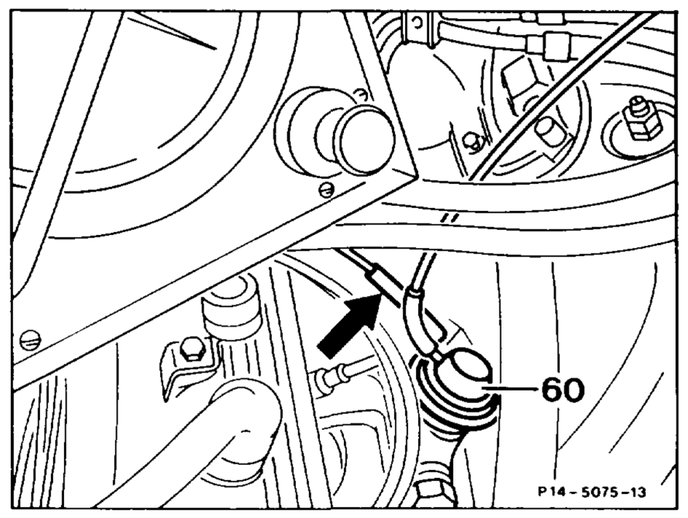
21 Test operation of exhaust gas recirculation valve. Detach vacuum line (arrow) at exhaust gas recirculation valve (60), connect tester to exhaust gas recirculation valve and pressurize with vacuum. If there is no clear deterioration in engine running, replace exhaust gas recirculation valve. Test actuation if necessary (14-7611).
23 Test idle speed (see table).
Note Idle speed can no longer be adjusted on engines with electronic idle speed control. !f the idle speed differs, perform test program (07.3-2006).
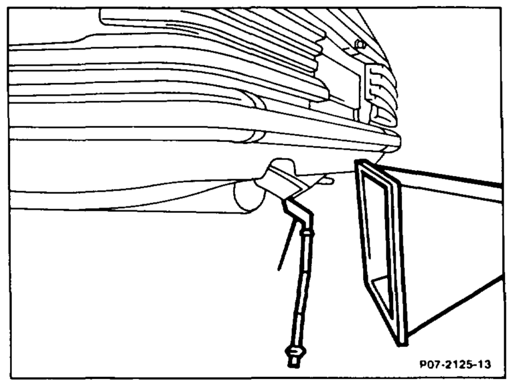
24 Test idle emissions level (see table); adjust if necessary (see step 26).
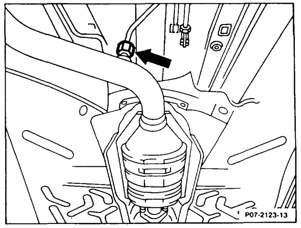
Measuring point at exhaust tailpipe
Measuring point (arrow) for open-loop KAT, upstream of Catalytic converter (only for adjustment work).
wii §=RA 07.3.1112-1100/15
Note The readout must fluctuate during the measurement. If a constant readout is indicated, there is a fault in the lambda control, e.g. oxygen sensor disconnected. For troubleshooting, see „Testing electrical components of KE injection system” (07.3-0121).
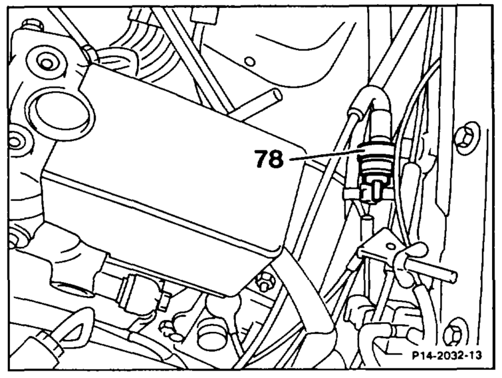
Detach regeneration line to throttle valve body at regeneration valve (78) and seal.
Connect lambda control tester to diagnostic socket (X11).
| Lambda control tester | Position |
| Bosch | 100% IR |
| Hermann | 100% @) |
Test on/off ratio at 2500/min and read off mean valule. Compare this reading with the idle speed value. The mean value at idle speed must not differ by more than + 10 from the reading obtained at 2500/min. Adjust lambda control (see step 26).
wii §=RA 07.3.1112-1100/16
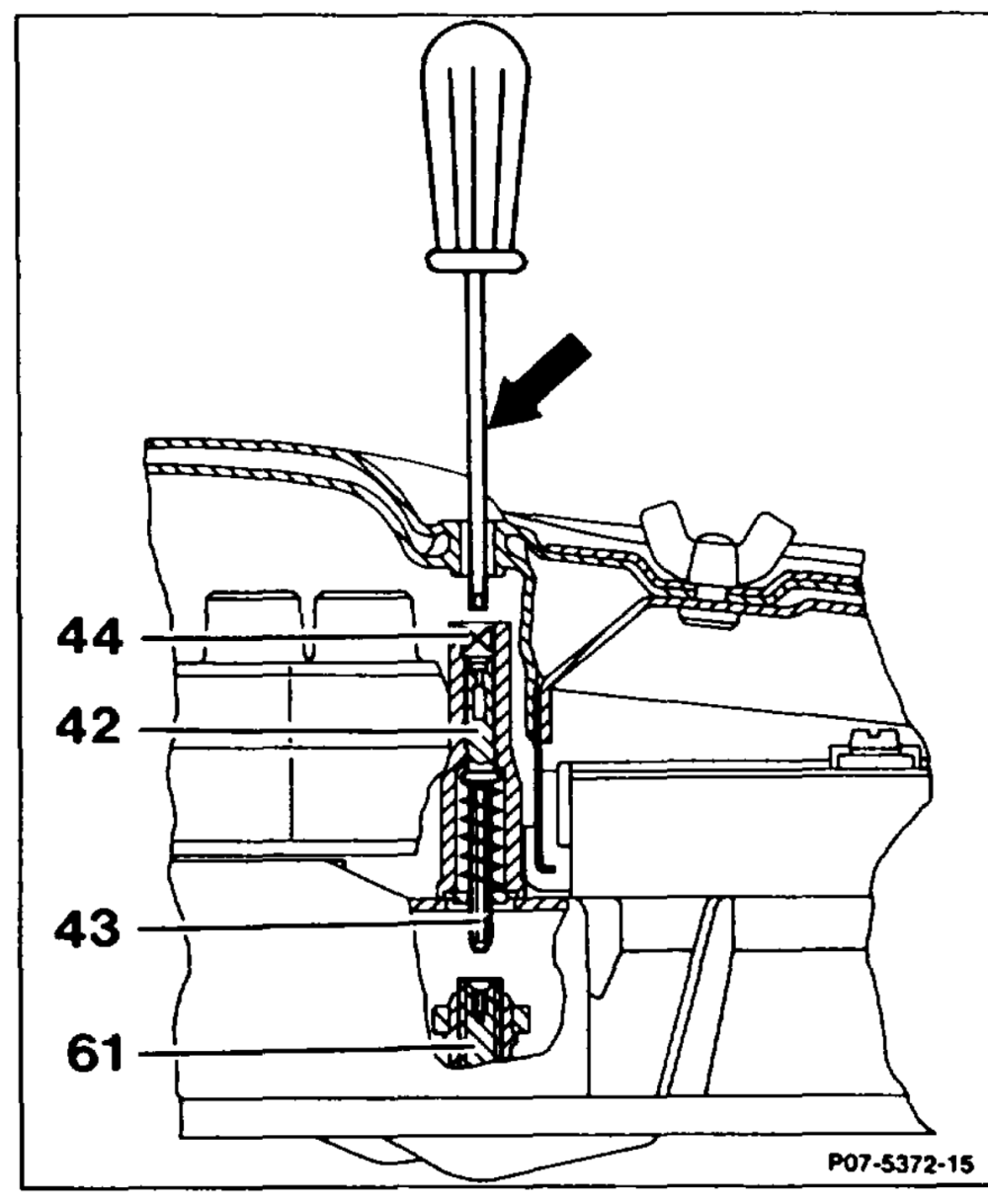
control. To do this remove anti-tamper plug (44) with the puller. Insert screwdriver (arrow) through the opening on the top of the air cleaner and push down on adjusting device (42). Push adjusting device down with screwdriver against spring force, turn slightly until the hexagon head (43) engages in the mixture regulating screw: Turning to the left =leaner — on/off ratio rises Turning to the right =richer —- on/off ratio drops
After each adjustment, briefly operate throttle; readjust if necessary. After the adjustment, insert a blue anti-tamper plug (44), part no. 000 997 59 86, with the insertion drift. Re-connect regeneration line (only if lambda control fitted).
27 Check that engine runs smoothly. To do this, move selector lever into Drive mode, switch on air conditioner/automatic climate control, turn power steering to full lock; engine must continue to run smoothly.