Checking basic position of hydraulic compensating elements
WIS 05-2130
Preceding work: Fan shroud removed (20-3400). Cylinder head cover removed (01-0500).
51
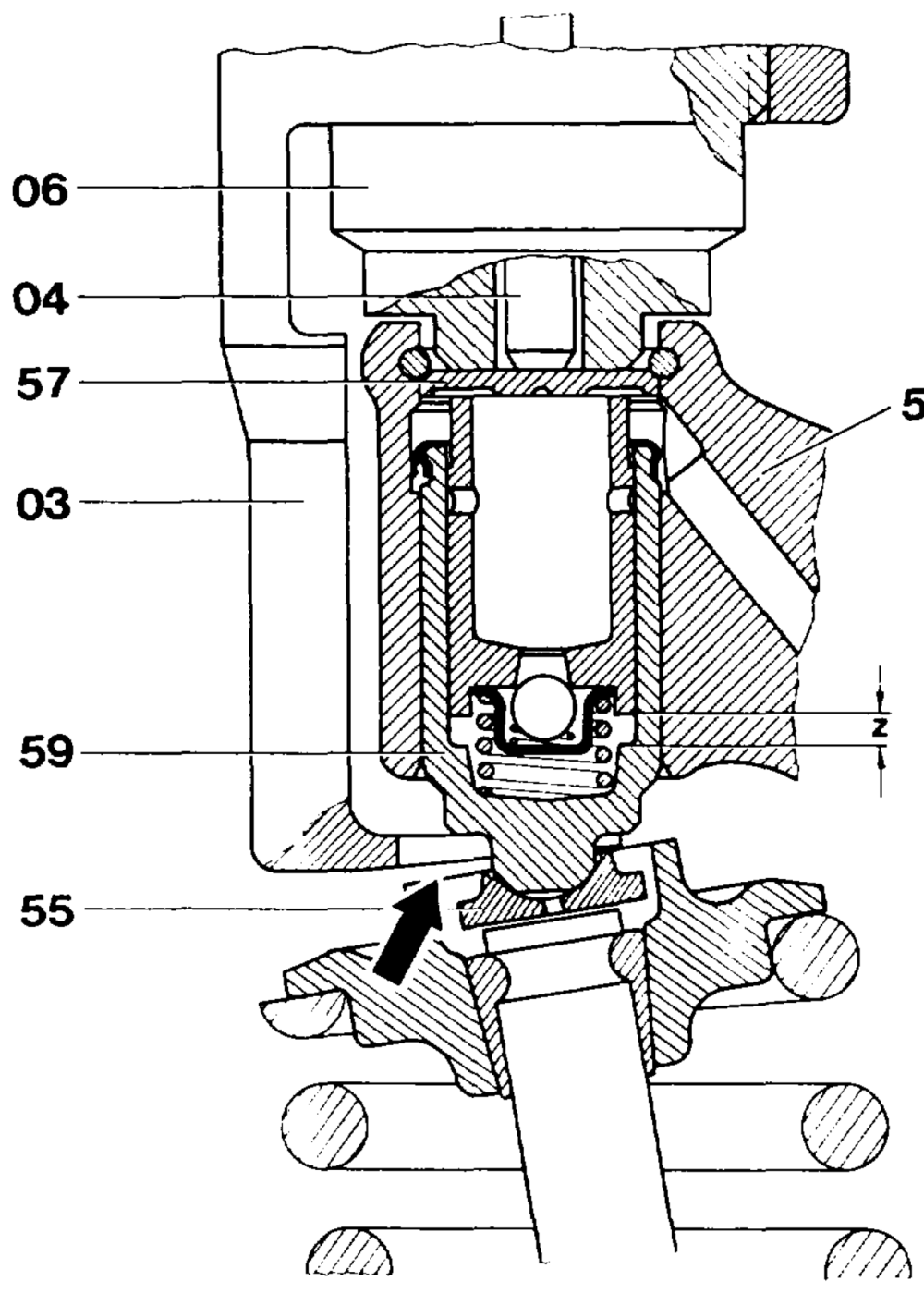
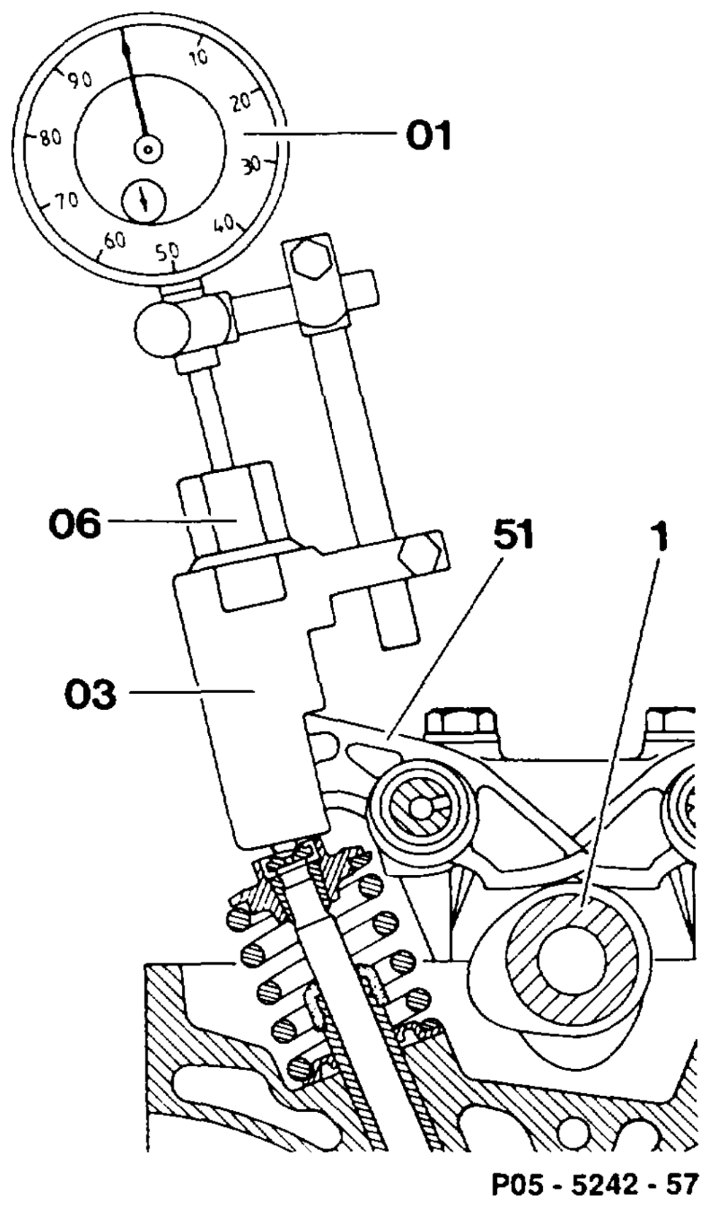
Crankshaft …….0….02.. 00000 eee eee eee rotate and position cam (1) of compensating element to be checked to base circle. Pronged sleeve (03) of measuring device 102 589 04 2100 2… eee eee position at guide sleeve (59) of compensating element (arrow). Hexagon head of thrust piece (06) ……….. screw in by hand until it touches the washer (57).
Note The thrust piece (06) must be touching the washer (57) of the compensating element and not the rocker arm (51) otherwise the residual stroke (z) measured will be incorrect.
aie §=RA 05.1123-2130/1
Dial gauge (01) with measuring pin insert into measuring device. (04) ……. clamp in measuring device with preload Dial gauge (01) …………. of 5 mm.
Large pointer of dial gauge …. set to ”0”. Hexagon head of thrust piece (06) screw in with wrench until residual stroke (z) is eliminated. Residual stroke (z) (adjustment) . read off on dial gauge (01), note. Residual stroke must be between 0.5 – 2.4 mm. If residual stroke is greater or less, adjust basic position of hydraulic compensating elements (05-2140).
A Stretched inlet valves may produce a residual stroke of less than 0.5 mm!
i i &
\ 102 589042100 \ 001589532100
Note The installation position of the hydraulic valve compensating elements must be checked:
@ if valve gear is noisy and no operating fault
of compensating element exists (05-2110).
@ if valves and valve seat rings have been
machined.
The compensating elements must be filled with engine oil for checking.