Replacement, centering and zero position of air flow sensor plate
|
|
||||
|
07.3—245 Replacement, centering and zero position of air flow sensor plate
|
||||
|
|
||||
|
Tightening torque
|
Nm
|
|||
|
|
||||
|
Hex. screw
|
5.0-5.5
|
|||
|
|
||||
|
Special tool
|
||||
|
|
||||
|
Torque wrench 1/4″ square, 4—16 Nm
|
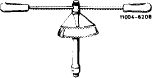 |
000 589 67 21 00
|
||
|
|
||||
|
Conventional equipment and tools
|
||||
|
|
||||
|
Hot air blower, tap M 6
|
||||
|
|
||||
|
Removal
|
 |
|||
|
1 Remove air cleaner.
|
||||
|
2 Unscrew stop bracket.
|
||||
|
|
||||
|
3 Heat fastening screw with a hot air blower and screw out with care (risk of tearing threads).
Attention!
The fastening screw is micro-encapsulated.
4 Clean bore for fastening air flow sensor plate with M 6 tap.
|
||||
|
|
||||
|
07.3.2 Ma—245/1 F2
|
||||
|
|
||||
|
|
|||
|
Installation
|
|||
|
|
|||
|
5 Install parts contained in repair kit. Make sure that the letters „TOP” are on top and insert air flow sensor plate. Lightly screw-in micro-encapsulated fastening screw (self-locking).
|
|||
|
|
|||
|
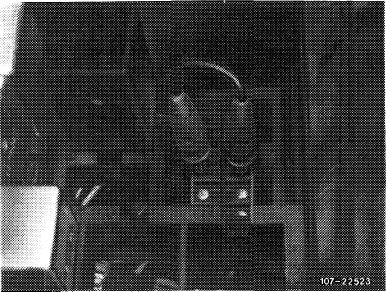
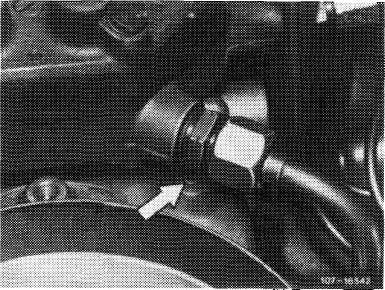
6 Center air flow sensor plate. For this purpose, pull off fuel pump relay (arrow) and bridge the two jacks short, or pull off plug on safety switch. Switch-on ignition for a short moment to establish control pressure.
Prior to September 1981: Jacks 1 and 2 Starting September 1981: Jacks 7 and 8
|
 |
||
|
|
|||
|
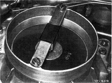
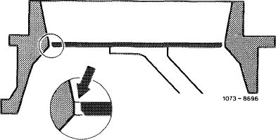
Use slip gauge 0.10—0.20 mm and make sure that the air flow sensor plate is accurately centered. Plate should not bind even under light lateral pressure (bearing play cancelled).
|
 |
||
|
|
|||
|
7 Tighten fastening screw to 5.0—5.5 Nm.
|
|||
|
|
|||
|
07.3.2 lla-245/2 F2
|
|||
|
|
|||
|
|
||||
|
8 Check air flow sensor plate for easy operation. For this purpose, push plate down manually. Plate should not bind. Release plate, which should also not bind when moving back and should audibly abut against resilient contact. Center air flow sensor plate again, if required.
|
||||
|
|
||||
|
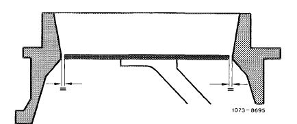
9 Check zero position (rest position) of air flow sensor plate. Upper edge of plate should close accura-rately flush with cylindrical part of of air funnel (arrow) along entire circumference. A higher location up to max. 0.5 mm is permitted.
Note: To check zero position, bridge electric safety circuit (refer to item 6). This will provide control piston with control pressure.
|
 |
|||
|
|
||||
|
10 Adjust zero position of air flow sensor plate:
a) If too high, lock guide pin (arrow) by means of a mandrel to required depth.
b) If too low, remove mixture controller and knock-in guide pin from below (07.3—200).
Attention!
Do not knock-in guide pin too low.
Avoid repeated adjustments in both directions, since the press fit of the pin will become too loose.
|
 |
|||
|
|
||||
|
11 Mount stop bracket and fuel pump relay or attach plug to safety switch.
12 Adjust idle speed (07.3-100).
|
||||
|
|
||||
|
07.3.2 lla-245/3
|
F 2
|
|||
|
|
||||