Removing, preventing formation of layer on breaker points (breaker-controlled transistorized ignitio
|
|
||
|
07.5—503 Removing, preventing formation of layer on breaker points (breaker-controlled transistorized ignition)
|
||
|
|
||
|
Conventional tool
|
||
|
|
||
|
Voltmeter with measuring range 0—3 volts
|
||
|
|
||
|
The formation of a blue or a dark grey layer on breaker points of transistorized ignition systems may result in misfiring when in a progressive stage due to the insulating characteristics of such a layer — no matter whether a GE or an SI switchgear is installed. Pertinent complaints resulted in an unjustified exchange of switchgear.
The formation of layers on breaker points is the result of various influences which are shortly explained below:
|
||
|
|
||
|
Blue layer
The blue layer (tungsten oxide) is formed by the arch occurring during the closing stage and the resulting burning of contact material. This arch is above all caused by the discharge of the anti-interference capacitor in ignition distributor.
A large closing angle (small contact spacing) favors the intensity of the arch and thereby the formation of a layer.
|
||
|
|
||
|
Dark grey layer
The dark grey layer is the result of burnt grease, oil or dirt particles formed between breaker points.
A remedy with regard to complaints concerning the formation of layers requires the following jobs:
1. Check on ignition distributor whether
a) a layer shows up on breaker point,
b) the cams are showing score marks (check with finger nail).
|
||
|
|
||
|
07.5.2 lb-503/1
|
||
|
|
||
|
|
|||
|
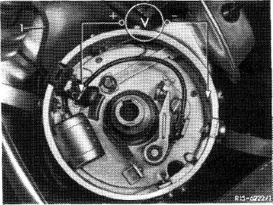
2. If a visual checkup shows no distinct fault, check function of points by measuring voltage drop. Use voltmeter with measuring range of 0—3 volts.
The voltage drop may amount to 0.5 volt with contact closed. A larger voltage drop is already indicating the formation of a layer.
|
 |
||
|
1 Control line with capacitor
|
|||
|
|
|||
|
Remedies
|
|||
|
|
|||
|
1. Lining on breaker points:
a) Exchange breaker points.
b) Remove control line with capacitor (1) and replace by shielded control line without capacitor.
2. Score marks in distributor cam or rubbed-through lubricator felt:
Exchange ignition distributor. Prior to installation, fit a shielded control line without capacitor to new ignition distributor.
|
|||
|
|
|||
|
Repair instructions
|
|||
|
|
|||
|
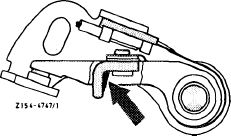
Breaker points
When renewing breaker points, be sure to coat slide piece (arrow) with a special grease pencil (special grease Bosch Ft 1 v 4). Without grease, the dwell angle will increase (smaller contact gap) due to the heavier wear of the slide piece. This in turn will favor the formation of a layer and may result in misfiring.
Arrow: point to be greased 07.5.2 lb-503/2
|
 |
||
|
|
|||
|
|
|||
|
Closing angle (dwell angle)
Set dwell angle to lower tolerance limit (07.5—500). This will guarantee that the dwell angle will not change beyond the specified value after running-in period of slide piece.
Adjusting values (lower tolerance) 34°
|
|||
|
|
|||
|
Protective breaker cap
Always mount protective breaker cap. Cap protects breaker point against grease, oil or dirt.
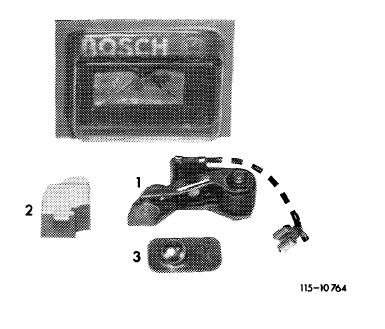
To make sure that during installation of breaker points the slide piece is greased and the protective cap is mounted, the breaker points are supplied with grease capsule and protective cap from now on.
|
 |
||
|
1 Breaker point
2 Protective cap
3 Grease capsule
|
|||
|
|
|||
|
07.5.2 lb-503/3
|
|||
|
|
|||