Removal, installation and adjustment of chassis regulating shaft
|
|
||||
|
30—320 Removal, installation and adjustment of chassis regulating shaft
|
||||
|
|
||||
|
A. Model 107
|
||||
|
|
||||
|
Adjusting value in mm
|
||||
|
|
||||
|
Length of pushrod (5)
|
105
|
|||
|
|
||||
|
Note
|
 |
|||
|
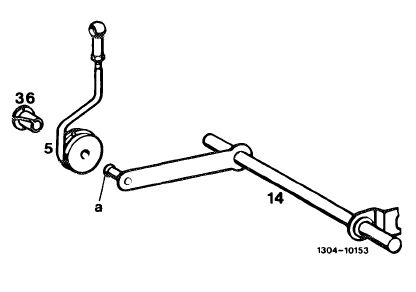
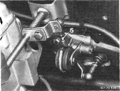
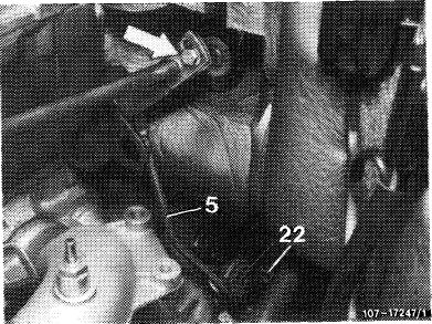
Since February 1981, pushrod (5) is mounted with a bearing bushing and collar (36) on front wall regulating shaft (14).
Subsequent installation is possible as follows:
|
||||
|
|
||||
|
Installation: February 1981
|
||||
|
|
||||
|
Model
|
Engine Chassis end No.
|
|||
|
|
||||
|
107.022 009866
107.042 11°-986 010249
|
||||
|
|
||||
|
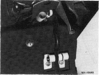
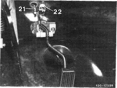
1 Slightly grease knob bolt (a) with Molykote-Longterm 2.
2 Insert bearing bushing with collar (36) in pushrod (5) and press pushrod on knob bolt (a). Pay attention to correct seat of bearing bushing.
|
||||
|
|
||||
|
30.2 Mb—320/1 F2
|
||||
|
|
||||
|
|
|||
|
Removal
|
 |
||
|
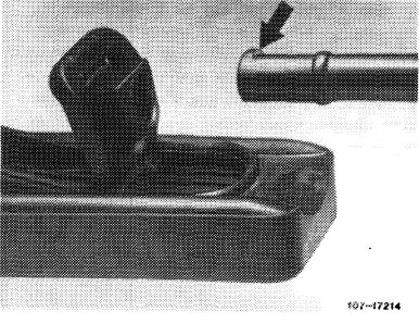
1 Push regulating rod with damping ring from lever of regulating shaft.
2 Remove accelerator pedal (30—330).
3 Remove heater box (83-100).
|
|||
|
|
|||
|
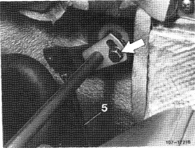
4 Disconnect restoring spring and unscrew fastening screws from plastic bearings.
5 Push out plastic bearings in upward direction and remove regulating shaft with bearing.
|
 |
||
|
|
|||
|
Installation
|
|||
|
|
|||
|
For installation proceed vice versa, while attaching restoring spring to inner hole.
Grease bearing points as well as ball sockets of regulation with Molykote-Longterm 2.
|
|||
|
|
|||
|
Checking and adjusting full throttle stop
|
 |
||
|
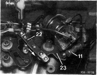
Attention!
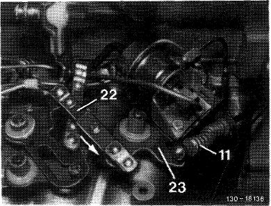
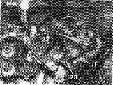
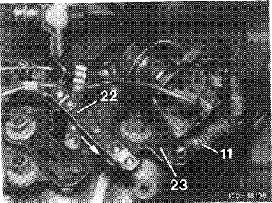
On vehicles with automatic transmission 722.3 (W 4 A 040) disconnect Bowden wire (11) and reconnect after adjusting full throttle stop.
|
|||
|
|
|||
|
30.2llb-320/2 F2
|
|||
|
|
|||
|
|
||||
|
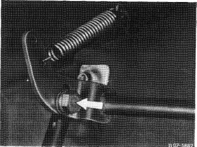
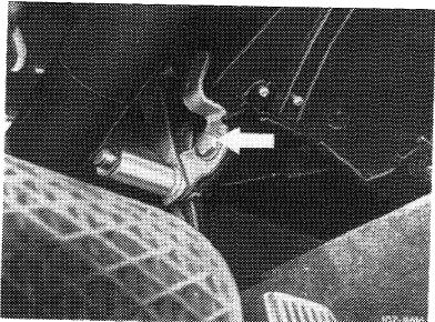
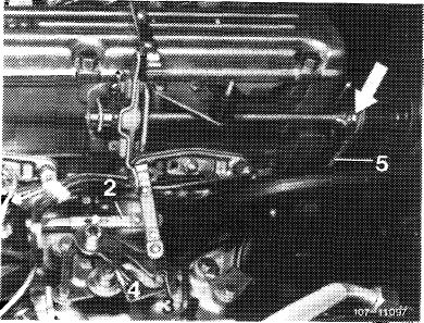
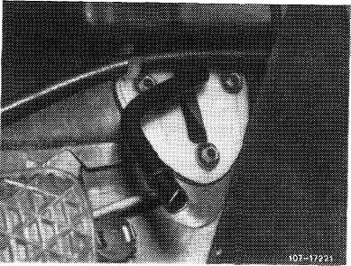
6 With engine stopped, step on accelerator pedal from inside vehicle up to full throttle stop or with automatic transmission up to stop on kickdown switch. Throttle valve lever should rest against full throttle stop. If required, adjust regulating linkage with adjusting screw (arrow) in such a manner that the throttle valve lever rests against full throttle stop.
If the full throttle or idle speed stop is not attained with this adjustment, setpushrod from longitudinal regulating shaft to accelerator pedal to 105 mm length, measured from center of ball socket to center of damping ring (refer to Fig. item 1).
|
 |
|||
|
|
||||
|
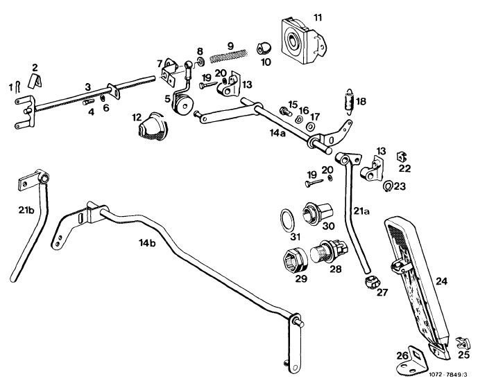
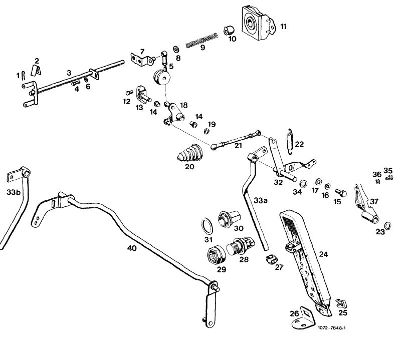
Chassis regulation
|
||||
|
|
||||
|
Model 107
|
||||
|
|
||||
 |
||||
|
|
||||
|
1 Lock
2 Spring
3 Longitudinal regulating shaft
4 Hex. screw
5 Pushrod
6 Washer
7 Guide lever for full throttle adjustment
8 Plastic spacer ring
9 Compression spring
10 Plastic ball
11 Bearing for longitudinal regulating shaft
12 Hex. screw
13 Bearing
14a Front wall regulating shaft lefthand steering 14b Front wall regulating shaft righthand steering
15 Hex. screw
16 Corrugated washer
|
17 Washer
18 Restoring spring
19 Screw
20 Washer
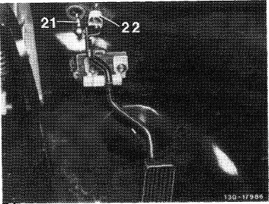
21a Accelerator lever lefthand steering 21b Accelerator lever righthand steering
22 Cage nut
23 Lock
24 Accelerator pedal
25 Clip
26 Fastening plate
27 Joint
28 Transition switch (kickdown)
29 Adjusting nut
30 Full throttle stop
31 Washer
|
|||
|
|
||||
|
30.2 llb-320/3 F 2
|
||||
|
|
||||
|
|
||||
|
B. Model 116
|
||||
|
|
||||
|
Adjusting value in mm
|
||||
|
|
||||
|
Length of connecting rod from accelerator pedal to guide lever
|
122
|
|||
|
|
||||
|
Length of pushrod (5)
|
68
|
|||
|
|
||||
|
Removal
|
 |
|||
|
1 Remove accelerator pedal (07.3-330).
2 Disconnect connecting rod.
3 Disconnect restoring spring, unscrew fastening nuts from bearing bracket and remove regulating shaft with bearing bracket.
|
||||
|
Lefthand steering
|
||||
|
|
||||
|
Installation
|
 |
|||
|
4 For installation proceed vice versa, while connecting restoring spring to inner hole. Grease bearing points as well as ball sockets of regulation with Molykote-Longterm 2.
|
||||
|
Righthand steering
|
||||
|
|
||||
|
Checking and adjusting full throttle stop
5 With engine stopped, step on accelerator from inside vehicle up to full throttle stop or with automatic transmission up to stop on kickdown switch. Throttle valve lever should rest against full throttle stop. If required, adjust regulating linkage with adjusting screw (arrow) in such a manner that the throttle valve lever rests against full throttle stop.
If the full throttle or idle speed stop is not attained with this adjustment, adjust pushrod (5) from longitudinal regulating shaft to accelerator pedal to 68 mm in length, measured from center of ball socket to center of damping ring. 30.2 llb-320/4 F2
|
 |
|||
|
|
||||
|
|
|||||
|
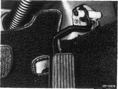
If the full throttle or idle speed stop is not attained with this adjustment, adjust connecting rod from guide lever engine compartment to accelerator pedal to 122 mm, measured from center of ball socket to center of ball socket. If required, adjust regulating lever inside vehicle. For this purpose, loosen fastening screw (arrow), pull accelerator pedal slightly in upward direction and tighten fastening screw again.
|
 |
||||
|
|
|||||
|
Chassis regulation
|
|||||
|
|
|||||
|
Model 116
|
|||||
|
|
|||||
 |
|||||
|
|
|||||
|
1 Lock
2 Spring
3 Longitudinal regulating shaft
4 Hex. screw
5 Pushrod
6 Washer
7 Guide lever for full throttle adjustment
8 Plastic spacer ring
9 Compression spring 10 Plastic ball
|
13 Bearing
14 Plastic bushing
15 Hex. screw
16 Corrugated washer
17 Washer
18 Guide lever
19 Lock
20 Rubber grommet
21 Connecting rod
22 Restoring spring
23 Lock
24 Accelerator pedal
|
25 Clip
26 Fastening plate
27 Joint
28 Kickdown switch
29 Adjusting nut
30 Full throttle stop
31 Washer
32 Guide lever
33a Accelerator lever lefthand steering 33b Accelerator lever righthand steering 34 Plastic spacer ring 40 Front wall regulating shaft righthand steering
|
|||
|
11 12
|
Bearing for longitudinal regulating shaft
|
||||
|
Hex. screw
|
|||||
|
|
|||||
|
30.2 llb-320/5 F2
|
|||||
|
|
|||||
|
|
|||
|
C. Model 123
|
-.a,
|
||
|
Removal
|
|||
|
1 Remove accelerator pedal (07.3—330).
2 Disconnect restoring spring and pushrod.
|
|||
|
|
|||
|
3 Unscrew plastic bearing inside vehicle and remove shaft by turning.
|
 |
||
|
Installation
|
|||
|
4 For installation proceed vice versa, while connecting restoring spring to inside hole. Grease bearing points as well as ball socket of regulation with Molykote-Longterm 2.
|
|||
|
Lefthand steering
|
|||
|
|
|||
|
Righthand steering
|
 |
||
|
|
|||
|
Checking and adjusting full throttle stop
|
 |
||
|
Attention!
On vehicles with automatic transmission 722.3 (W 4 A 040) disconnect Bowden wire (11) and reconnect after adjusting full throttle stop.
|
|||
|
|
|||
|
30.2 llb-320/6 F2
|
|||
|
|
|||
|
|
||||
|
5 With the engine stopped, step on accelerator pedal from inside vehicle up to full throttle stop or with automatic transmission up to stop on kickdown switch. Throttle valve lever should rest against full throttle stop. If required, adjust regulating linkage with adjusting screw (arrow) in such a manner that the throttle valve lever rests against full throttle stop.
If the full throttle or idle speed stop is not attained with this adjustment, adjust pushrod (5) from longitudinal regulating shaft to accelerator pedal to 186 mm length, measured from center of ball socket to center of damping ring.
|
 |
|||
|
|
||||
|
Chassis regulation
|
||||
|
|
||||
|
Model 123
|
||||
|
|
||||
|
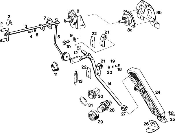
1
1 Lock
2 Spring
3 Longitudinal regulating shaft
4 Hex screw
5 Pushrod
6 Washer
7 Guide lever for full throttle adjustment
8 Bearing for longitudinal regulating shaft 1st version 8a Bearing 2nd version
8b Fastening plate 2nd version
9 Corrugated washer
10 Screw
11 Rubber grommet
12 Plastic spacer ring
13 Restoring spring
14 Accelerator lever
18 Hex. screw
19 Corrugated washer
20 Washer
21 Bearing
22 Gasket
24 Accelerator pedal
25 Clip
26 Fastening plate
27 Joint
28 Kickdown switch
|
1073-78111
|
|||
|
29 Adjusting nut
30 Full throttle stop
31 Washer
|
||||
|
|
||||
|
30.2 lib—320/7 F 2
|
||||
|
|
||||
|
|
||||
|
D. Model 126
|
||||
|
|
||||
|
Adjusting values in mm
|
||||
|
|
||||
|
Lefthand steering
|
||||
|
|
||||
|
Length of pushrod (5) from longitudinal regulating shaft to accelerator pedal
|
220
|
|||
|
|
||||
|
Righthand steering
|
||||
|
|
||||
|
Length of connecting rod (21) from accelerator pedal to guide lever Length of connecting rod (40)
|
172
|
|||
|
597
|
||||
|
|
||||
|
Removal
|
 |
|||
|
1 Disconnect restoring spring (22) and push off connecting rod (5 or 21).
2 Remove accelerator pedal (30—330).
|
||||
|
Lefthand steering
|
||||
|
|
||||
|
Righthand steering
|
 |
|||
|
|
||||
|
30.2 llb-320/8 F 2
|
||||
|
|
||||
|
|
|||
|
3 Unscrew fastening screws on bearing bracket, remove bearing bracket and accelerator lever.
|
 |
||
|
Lefthand steering
|
|||
|
|
|||
|
Righthand steering
|
 |
||
|
|
|||
|
Installation
|
 |
||
|
4 For installation proceed vice versa.
Grease bearing points as well as ball sockets of regulation with Molykote-Longterm 2.
The connection from accelerator lever to accelerator pedal is maintenance-free and requires no lubrication.
|
|||
|
|
|||
|
Checking and adjusting full throttle stop
|
 |
||
|
Lefthand steering
Attention!
On vehicles with automatic transmission 722.3 (W 4 A 040) disconnect Bowden wire (11) and reconnect after adjusting full throttle stop.
|
|||
|
|
|||
|
30.2 llb-320/9 F2
|
|||
|
|
|||
|
|
|||
|
5 With engine stopped, step on accelerator pedal from inside vehicle up to full throttle stop or with automatic transmission up to stop on kickdown switch. Throttle valve lever should rest against full throttle stop. If required, adjust regulating linkage with adjusting screw (arrow) in such a manner that the throttle valve lever rests against full throttle stop.
If the full throttle or idle stop is not attained with this adjustment, adjust pushrod (5) from longitudinal regulating shaft to accelerator pedal to 220 mm in length measured from center of ball socket to center of damping ring.
|
 |
||
|
|
|||
|
Righthand steering
Attention!
On vehicles with automatic transmission 722.3 (W 4 A 040) disconnect Bowden wire (11) and reconnect after adjusting full throttle stop.
|
 |
||
|
|
|||
|
6 With engine stopped, step on accelerator pedal from inside vehicle up to full throttle stop or with automatic transmission up to stop on kickdown switch. Throttle valve lever should rest against full throttle stop. If required, adjust regulating linkage with adjusting screw (arrow) in such a manner that the throttle valve lever rests against full throttle stop.
|
 |
||
|
|
|||
|
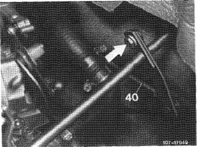
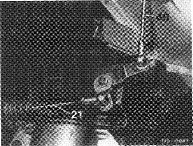
If the full throttle or idle speed stop is not attained with the previous adjustment, adjust connecting rod (21) from guide lever engine compartment to accelerator pedal and connecting rod (40) to specified length, measured from center of ball socket to center of ball socket.
Connecting rod (21) 172 mm Connecting rod (40) 597 mm
|
 |
||
|
|
|||
|
30.2 llb-320/10 F2
|
|||
|
|
|||
|
|
||||
|
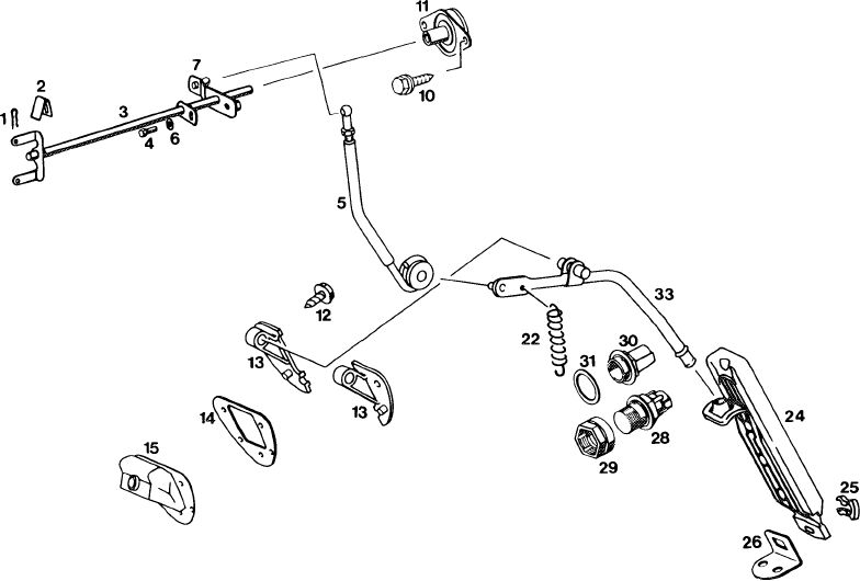
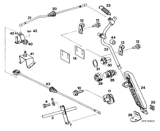
Chassis regulation Lefthand steering model 126
|
||||
|
|
||||
 |
1072-9126/2
|
|||
|
|
||||
|
1 Lock
2 Spring
3 Longitudinal regulating shaft
4 Hex. screw
5 Pushrod
6 Washer
7 Guide lever for full throttle adjustment
10 Hex. screw
11 Bearing for longitudinal regulating shaft
12 Hex. screw
13 Bearing
|
14 Intermediate plate
15 Rubber sleeve 22 Restoring spring
24 Accelerator pedal
25 Clip
26 Fastening plate
28 Kickdown switch
29 Adjusting nut
30 Full throttle stop
31 Washer
33 Accelerator lever
|
|||
|
|
||||
|
30.2 lib—320/11 F2
|
||||
|
|
||||
|
|
||||||||||||||||||||||||||||||||||||||||||||||||||||||||||||||||||||||||||||||||||||||||||||||||||
|
Righthand steering mode! 126
|
||||||||||||||||||||||||||||||||||||||||||||||||||||||||||||||||||||||||||||||||||||||||||||||||||
|
|
||||||||||||||||||||||||||||||||||||||||||||||||||||||||||||||||||||||||||||||||||||||||||||||||||
 |
||||||||||||||||||||||||||||||||||||||||||||||||||||||||||||||||||||||||||||||||||||||||||||||||||
|
|
||||||||||||||||||||||||||||||||||||||||||||||||||||||||||||||||||||||||||||||||||||||||||||||||||
|
||||||||||||||||||||||||||||||||||||||||||||||||||||||||||||||||||||||||||||||||||||||||||||||||||
|
|
||||||||||||||||||||||||||||||||||||||||||||||||||||||||||||||||||||||||||||||||||||||||||||||||||
|
30.2 llb-320/12 F2
|
||||||||||||||||||||||||||||||||||||||||||||||||||||||||||||||||||||||||||||||||||||||||||||||||||
|
|
||||||||||||||||||||||||||||||||||||||||||||||||||||||||||||||||||||||||||||||||||||||||||||||||||