Adjusting regulating linkage, vehicles with lefthand steering
WIS 30-300
A. Engine 615, 616 with M-injection pump
Length of regulating linkage
| rod unit to angle lever, Fig. item 4) | 1st version 2nd version | 310 mm 317 mm |
| lever to tickler shaft) | Ist version 2nd version | 205 mm 225 mm |
Adjusting gauge Cee – 115 589 30 23 00
Adjusting
1 Check regulating linkage for easy operation and distortion. Replace damaged parts, if any.
2 Disconnect the three regulating rods.
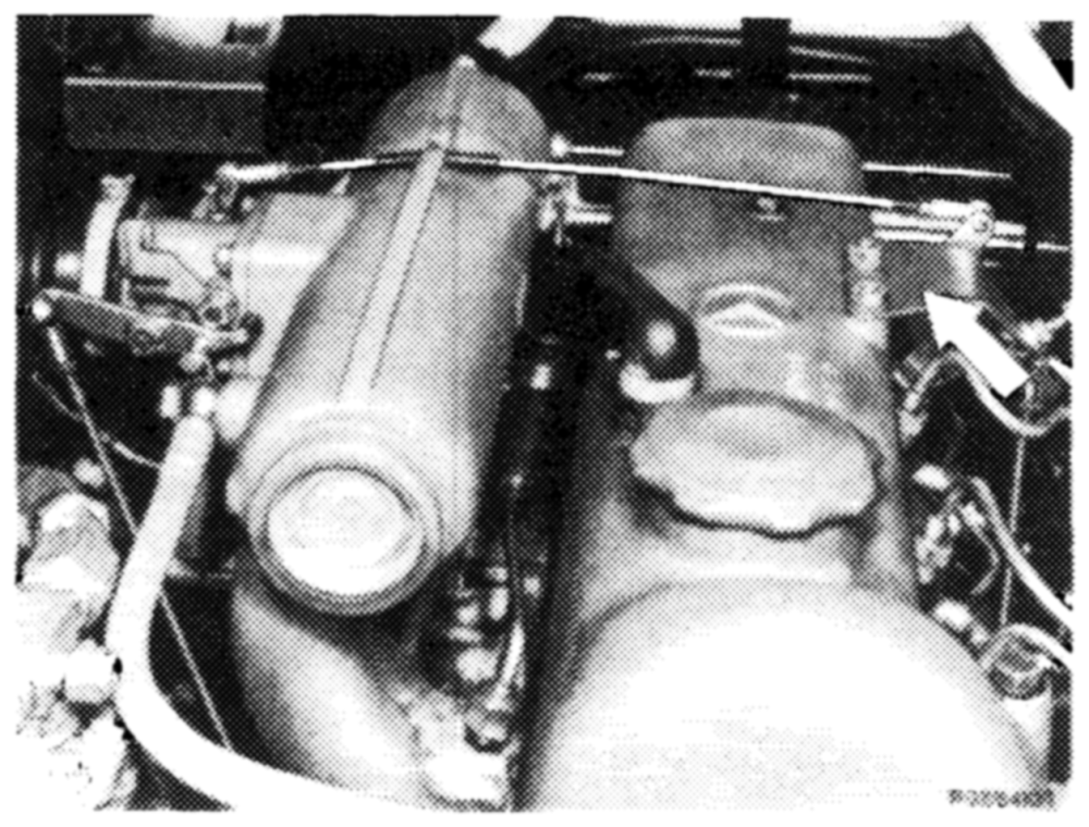
3 Check whether throttle valve closes completely without binding.
4 Adjust connecting rod from throttle unit to angle lever to a length of 310 mm on (st version or 317 mm on 2nd version, measured from center to center of ball head.
1st version flat bearing bracket
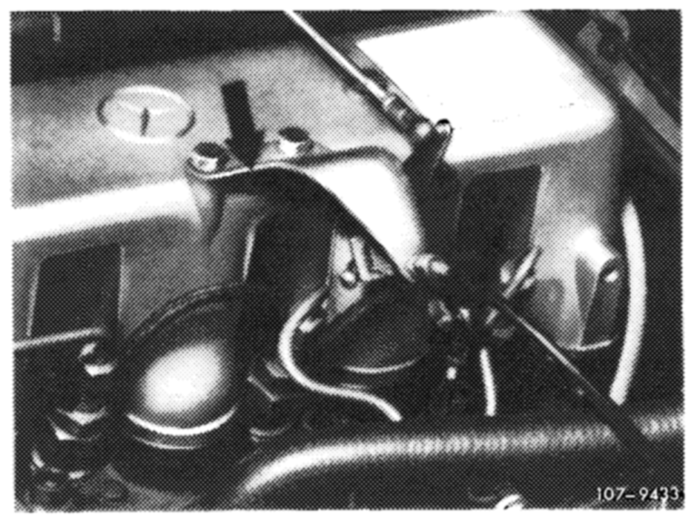
2nd version offset bearing bracket
5 Vehicles with automatic transmission:
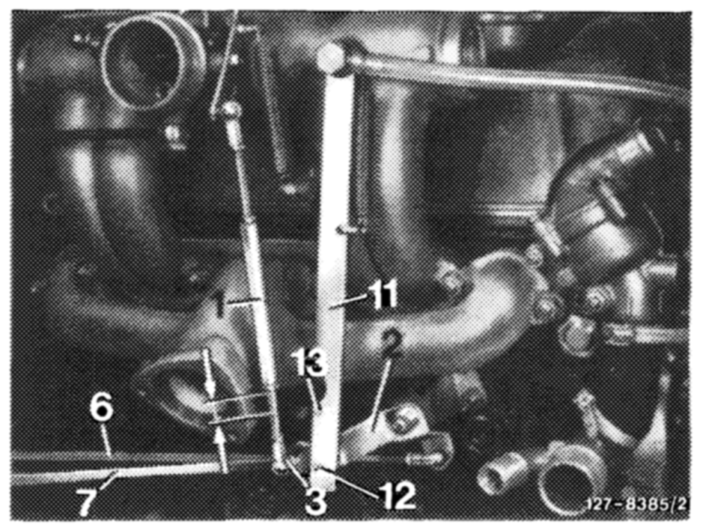
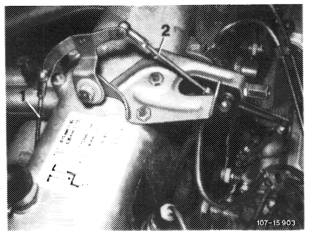
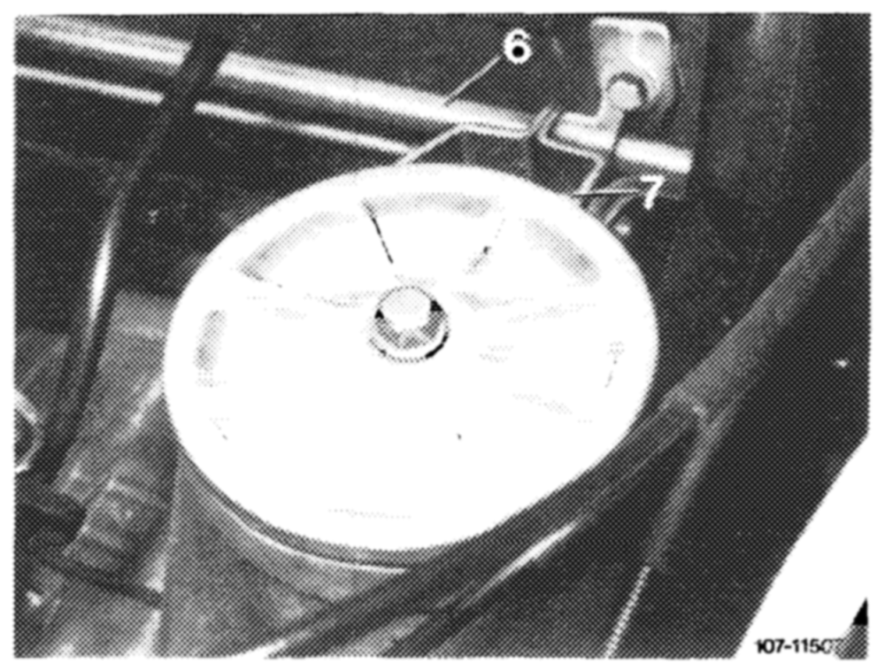
Disconnect resilient pull rod (1), control pressure rod (7) and push rod (6).
1 Resilient pull rod 7 Control pressure rod L = idle travel 11. Adjusting gauge
2 Intermediate lever 12 Full throttle detent
3 Adjustable ball head 13 Idle throttle detent
6 Push rod
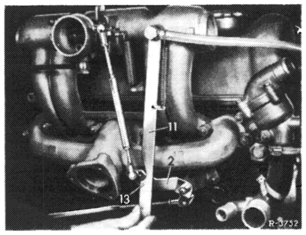
Attach adjusting gauge (11) with idle throttle detent (13) to intermediate lever (2).
Push resilient pull rod (1) completely together and attach free of tension, adjust if required. Throttle valve should rest against idle speed stop.
Push control pressure rod (7) completely to the rear to idle throttle stop and connect free of tension. Adjust with ball socket, if required.
2 Intermediate lever 13 Idle throttle detent 11. Adjusting gauge
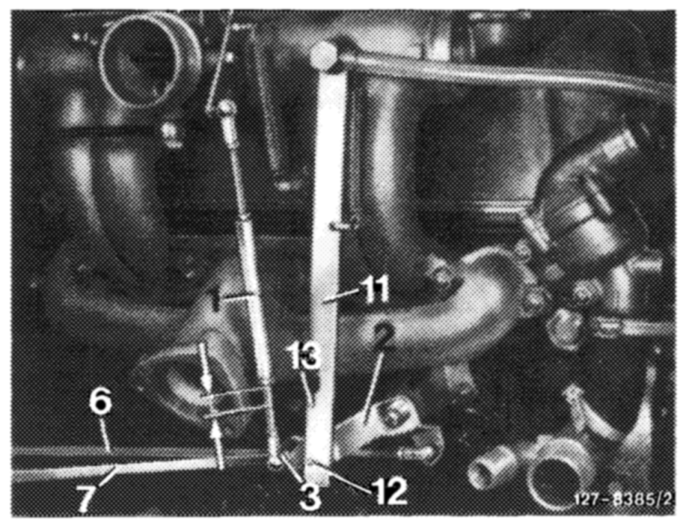
Attach push rod (6) free of tension and adjust, if required. Remove adjusting gauge (11) and accelerate to full throttle by means of accelerator pedal. Adjusting gauge (11) should permit attachment to full throttle detent (12) free of tension. Adjust front wall regulating shaft, if required (refer to item 7). Push intermediate lever (2) down, resilient pull rod (1) should then permit additionally extension for another 6 mm in relation to idle travel ‘“‘L’’. Loosen adjustable ball head (3), if required, and adjust. Remove adjusting gauge and check kick-down position.
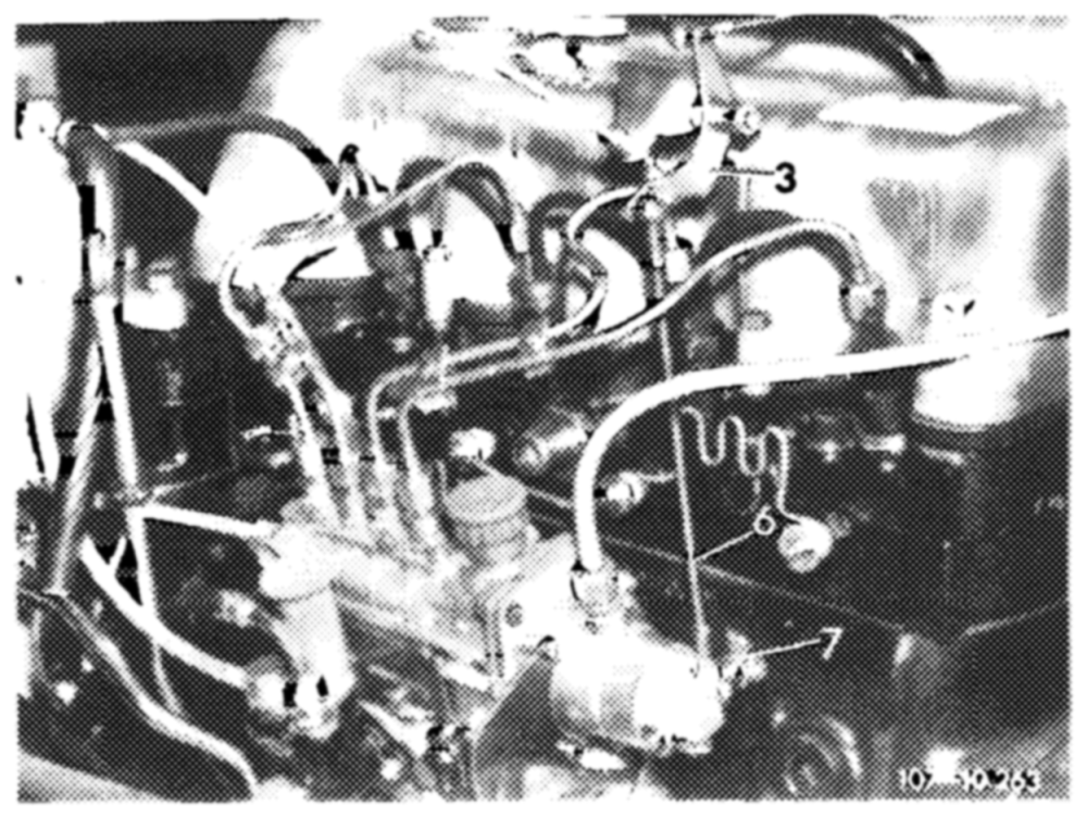
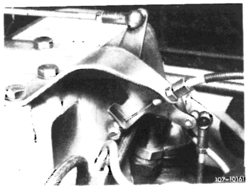
6 Adjust tickler. Disconnect connecting rod (6) from guide lever to tickler shaft on guide lever (3).
Push connecting rod (6) downwards up to stop by means of actuating lever (7).
3 Guide lever 7 Actuating lever 6 Connecting rod
For attaching connecting rod (6), lift rod by 4 mm (half of ball head). Adjust, if required.
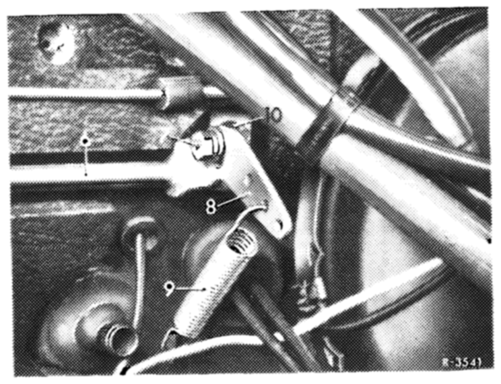
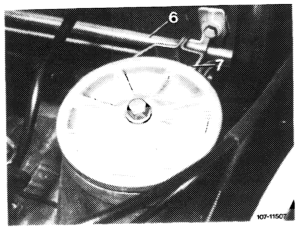
7 Check full throttle stop. With engine stopped, step down one accelerator pedal from inside vehicle up to or on vehicles with automatic transmission up to stop on kickdown switch. Accelerator pedal and the throttle valve lever should rest against full throttle stop. Adjust regulating shaft (6), if required.
For this purpose, loosen hex screw (7), pull accelerator pedal slightly outwards and tighten hex screw again. Check full throttle stop once again and repeat adjustments, if required.
Model 115.1
Model 123.1
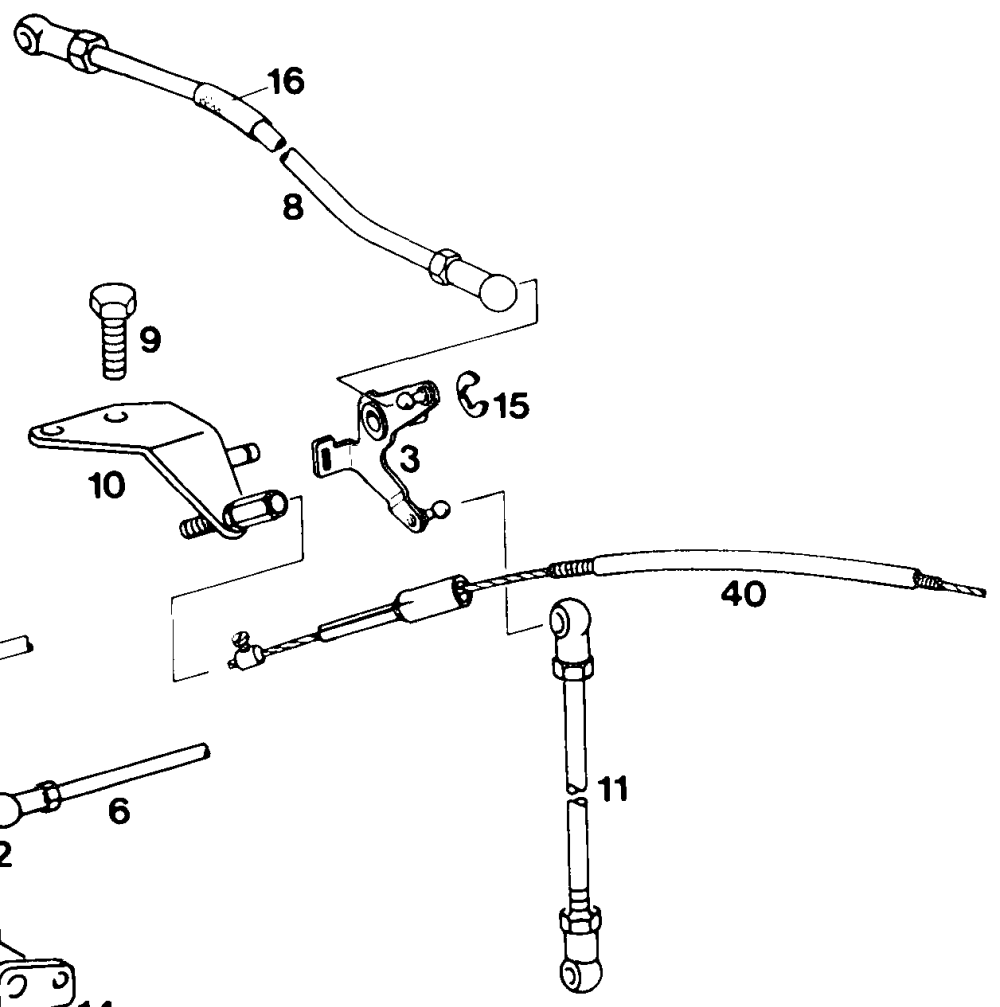
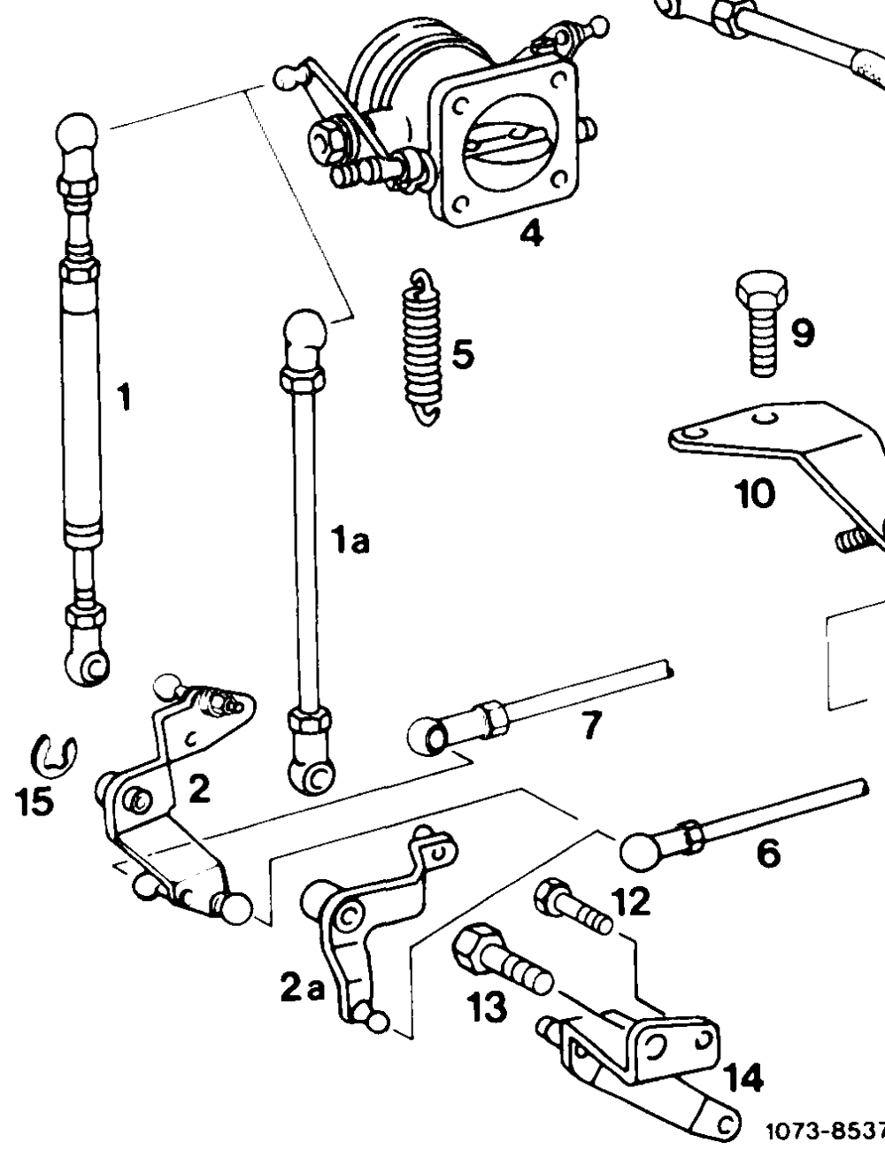
Engine 615, 616 M-injection pump with pneumatic governor
1 Idle path rod (automatic transmission) 6 Connecting rod to front wall Hex screw 1a Push rod (manual transmission) regulating shaft Hex screw
2 Intermediate lever (automatic transmission) 7 Control! pressure rod Bearing 2a Intermediate lever (manual transmission) 8 Connecting rod Lock
3 Angle lever 9 Hex screw Rubber hose
4 Throttle unit 10 Holder Bowden wire for idle speed ajuster
5 Return spring 11° Pull rod
Pull rod (3 in Fig. item 4) 225 mm
| rod (2 in Fig. item 4) manual transmission (2 in Fig. item 4) for automatic transmission extended | 158 mm |
| (1 in Fig. item 4) | 252 mm |
Adjusting
1 Check regulating linkage for easy operation and distortion. Replace damaged parts, if any.
2 Disconnect all regulating rods.
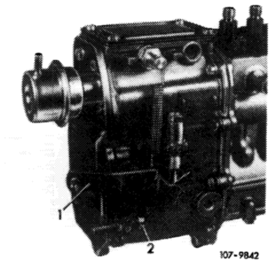
3 Check whether regulating lever (1) of injection pump rests against idle speed stop (3).
1 Regulating lever 3 Idle speed stop 2 Full throttle stop
4 Vehicles with manual transmission:
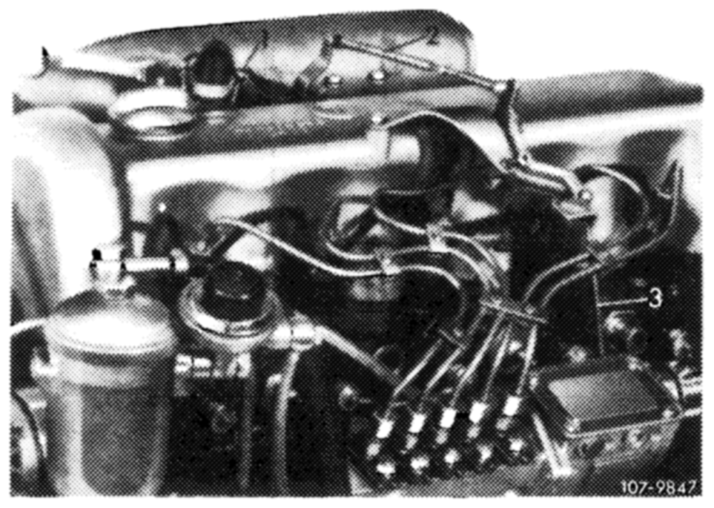
a) Adjust push rod (1) and pull rod (3) to specified length, measured from center to center of ball head and attach.
Attention! Pull rod (3) should be covered with an insulating hose.
1 Push rod 3 Pull rod 2 Connecting rod
b) Attach connecting rod (2) free of tension and adjust, if required.
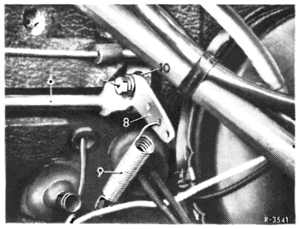
on accelerator pedal from inside vehicle up to stop. Accelerator pedal and regulating lever (1) should rest against full throttle stop (Fig. item 3). Adjust regulating shaft (6), if required. For this purpose, loosen hex screw (7), pull accelerator pedal slightly up and tighten hex screw again. Check full throttle stop once again and repeat adjustments, if required.
Attention!
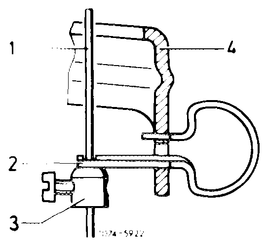
If the regulating linkage is not moving to full throttle, check whether shaped spring for idle speed adjuster is correctly installed.
1 Cable control for idle speed increase PWN Shaped spring Adjusting ring Guide lever
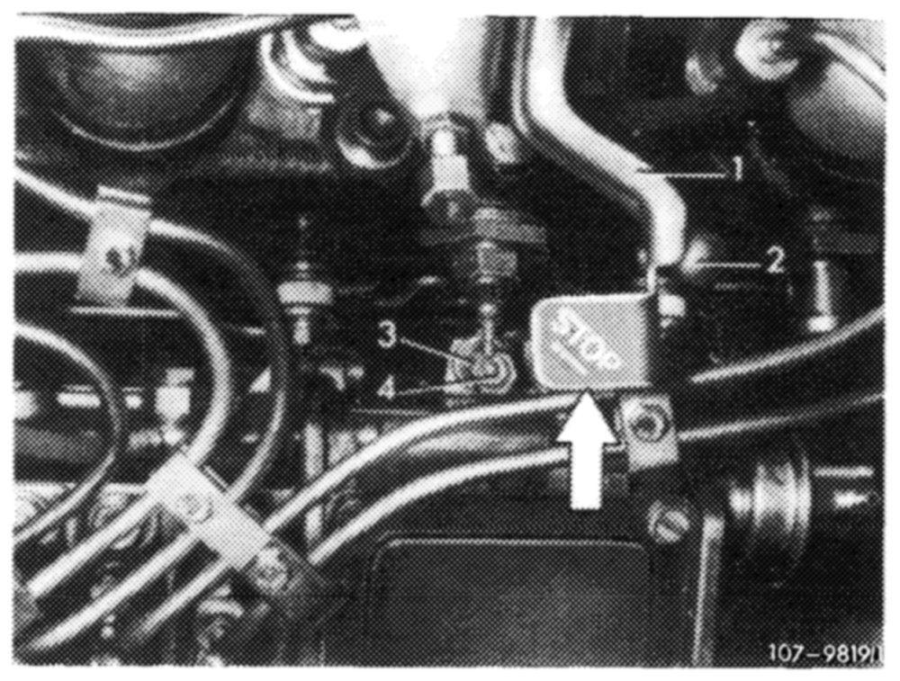
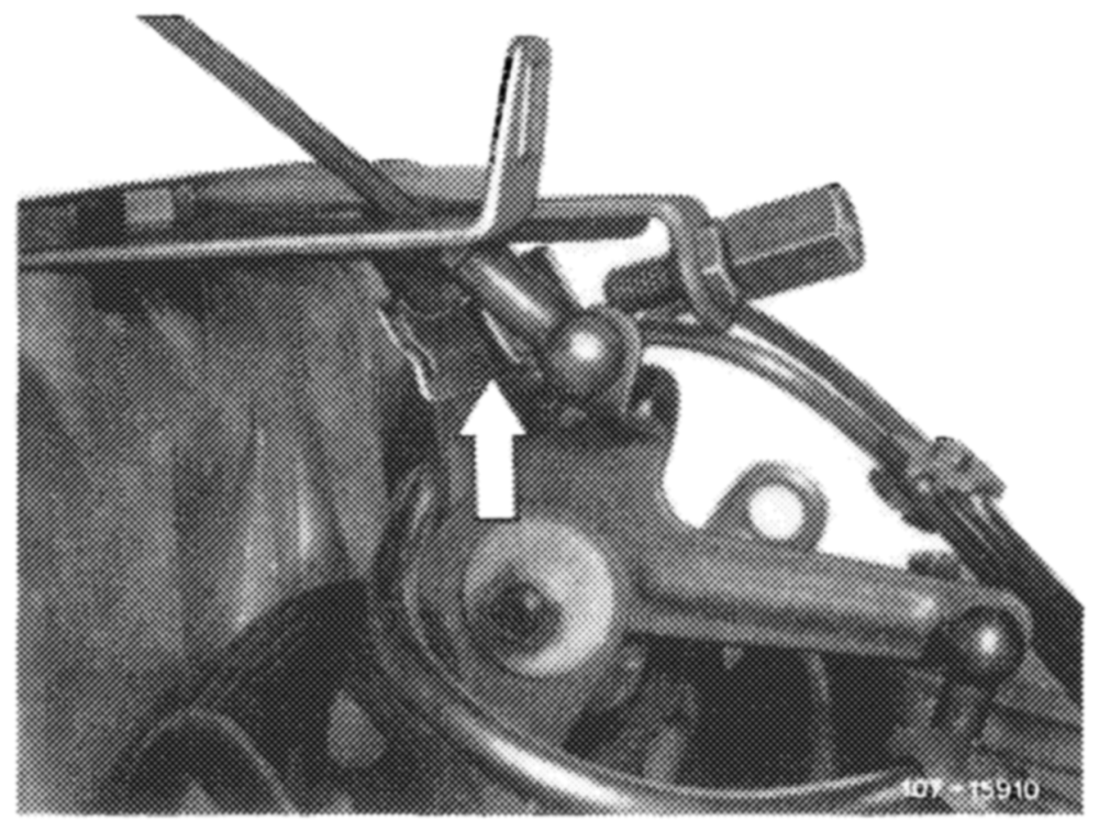
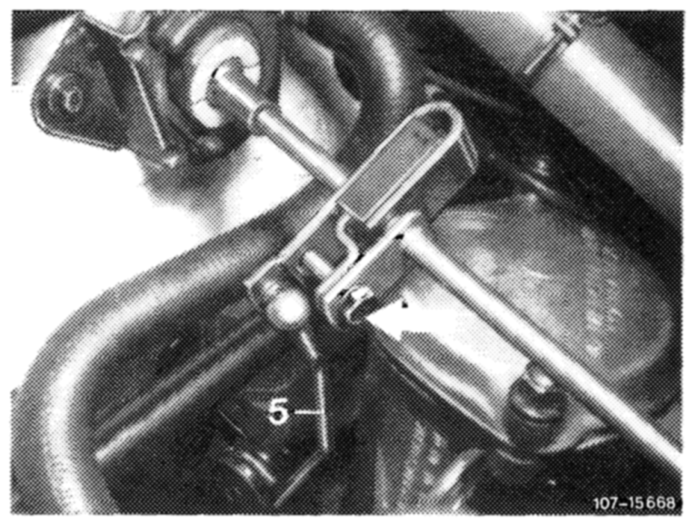
5 Check function of emergency stop button. Run engine at idle speed, push emergency stop button (arrow). Engine should stop. Adjust pull rod (2) if required.
1 Pushrod 3 Pull rod 2 Slide rod
6 Vehicles with automatic transmission:
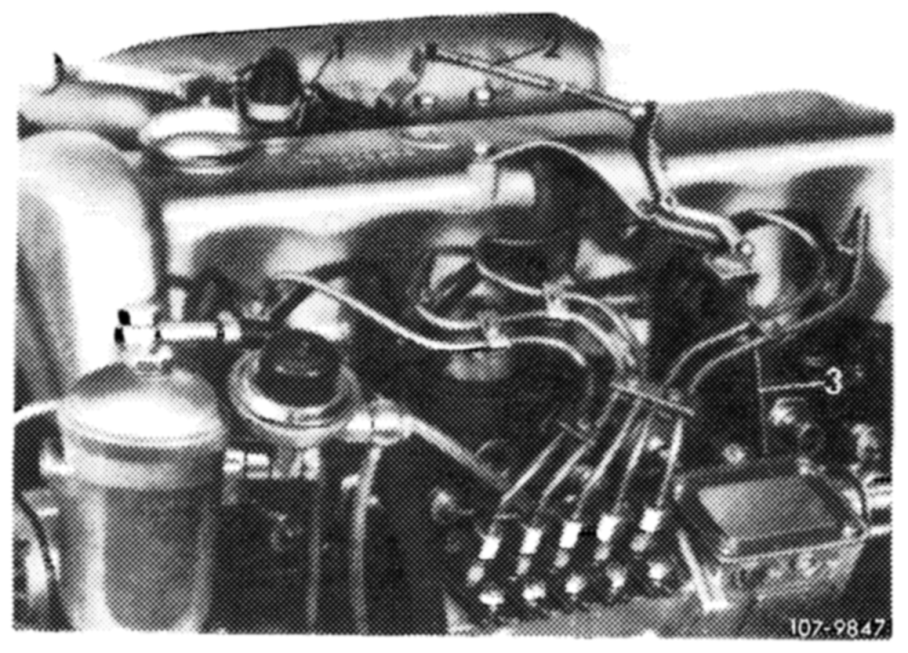
a) Adjust push rod (1) to 252 mm and pull rod (3) to 225 mm, measured from center to center of ball head, and attach.
Attention! Pull rod (3) should be covered with an insulating hose.
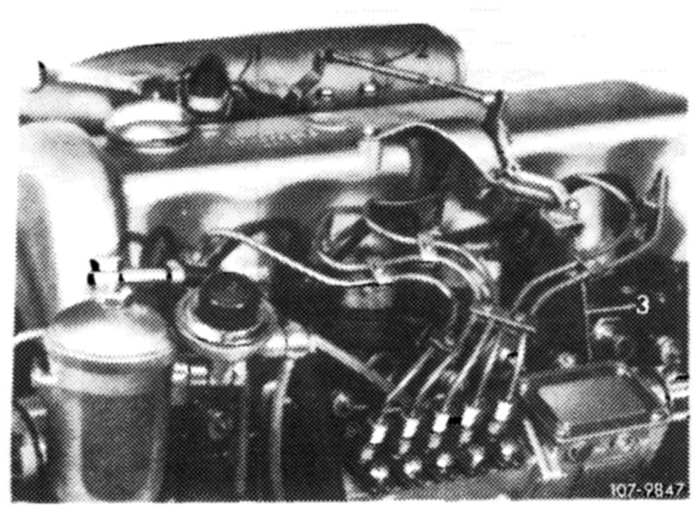
b) Adjust slide rod (2) in completely extended condition to a length of 158 mm, measured from center of ball head, and attach.
Note: For attachment, the slide rod need not be completely pulled out.
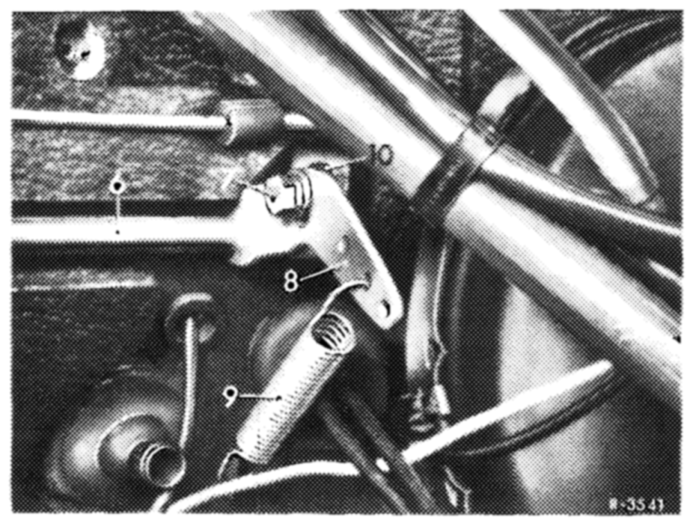
c) Check full throttle stop. With the engine stopped, step down on accelerator pedal from inside vehicle up to stop on kickdown switch. Accelerator pedal and regulating lever (1) should rest against full throttle stop (Fig. item 3). Adjust regulating shaft (6), if required. For this purpose, loosen hex screw (7), pull accelerator pedal slightly up and tighten hex screw again. Check full throttle stop once again and repeat adjustments, if required.
Attention!
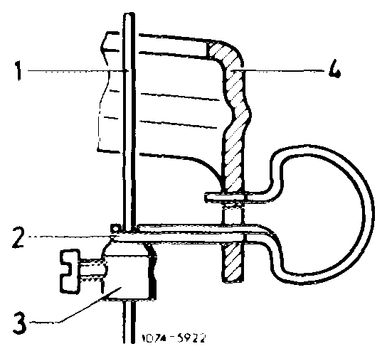
If the regulating linkage is not moving to full throttle, check whether shaped spring for idle speed adjuster is correctly installed.
1 Cable control for idle speed increase Pwn Shaped spring Adjusting ring Guide lever
d) Adjust control pressure rod.
Attention! Due to working pressure control (proportional to engine torque) it is extremely important that the control pressure rod is correctly adjusted.
A wrongly adjusted control pressure rod will lead to a reduction of the working pressure and will thereby make the gears ineffective.
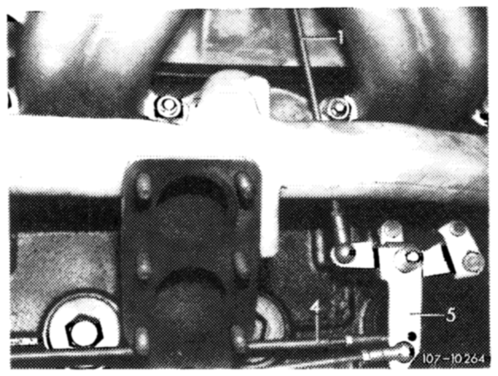
(not kickdown). Disconnect control pressure rod (4) and pull completely forward to full throttle stop. Adjust control pressure rod with ball socket in such a manner that it can be pushed on ball head of guide lever (5) free of tension.
1 Push rod 5 Guide lever 4 Control pressure rod
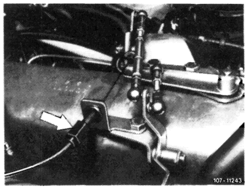
e) Adjust Bowden wire for Tempomat (cruise control). For this purpose, push shutoff lever up to stop. Bowden wire should rest against regulating lever free of tension. Adjust Bowden wire with adjusting nut (arrow), if required. Release shutoff lever (idle speed position). In this position, Bowden wire is slack.
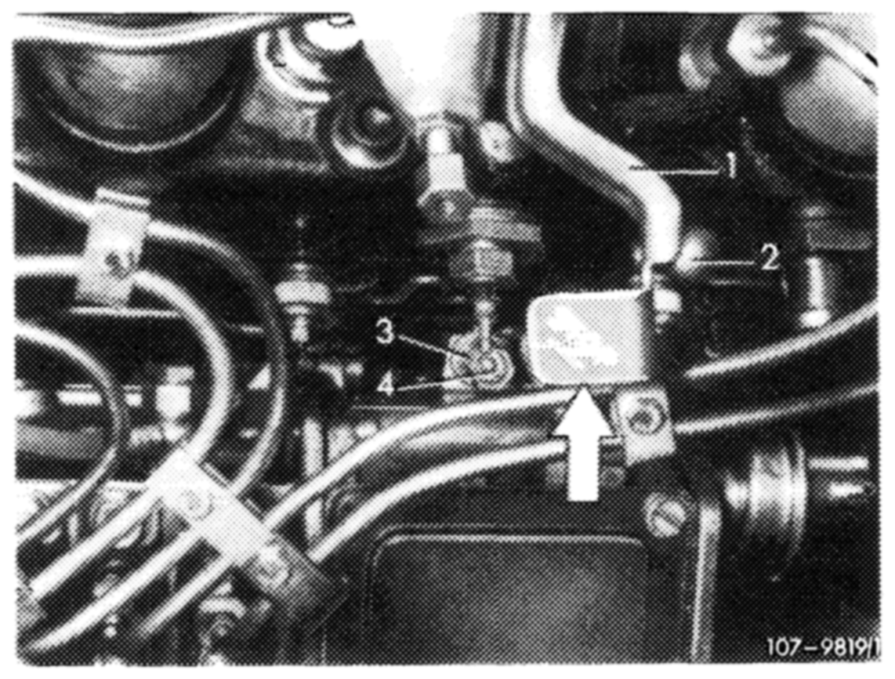
7 Check function of emergency stop button. Run engine at idle speed, push emergency stop button (arrow). Engine should shut off. Readjust pull rod (2), if required.
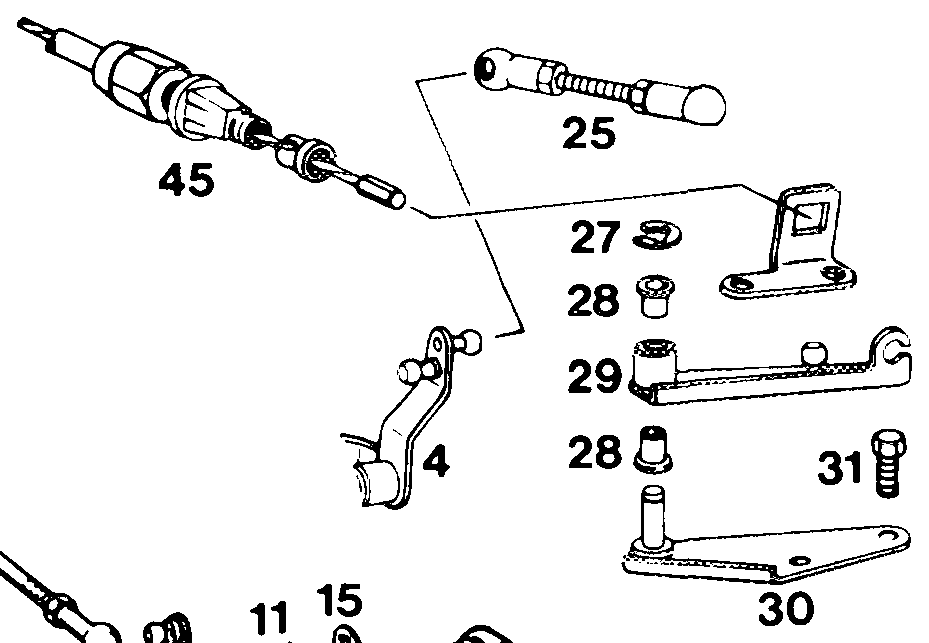
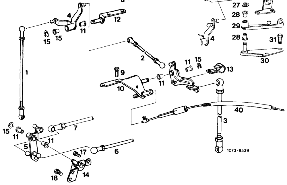
Engine 617 in model 115.1 MW-injection pump with mechanical governor
1 Push rod 11 Plastic bushing USA version
2 Connecting rod 12 Bearing 25 Connecting rod
3 Pull rod 13 Shaped spring 26 Holder
4 Guide lever 14 Bearing 27° ~Lock
5 Intermediate lever 15 Lock 28 Plastic bushing
6 Connecting rod to front wall 16 Angle lever 29 Guide lever regulating shaft 17 Hex screw 30 Holder
7 Control pressure rod 18 Hex screw 31° Hex screw
8 Hex screw 40 Bowden wire for idle speed adjuster
9 Hex screw 45 Bowden wire for Tempomat
10 Holder (cruise control)
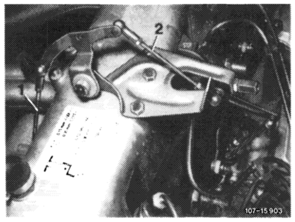
with MW-injection pump Standard version and @us) G) CG) @® up to 1979
Length of regulating linkage
Connecting rod (2) from guide lever to regulating lever on cylinder head cover 122 mm (manual transmission)
Connecting rod (1) from regulating lever on cylinder head cover to regulating lever 327 mm on cylinder crankcase
Adjusting
1 Check regulating linkage for easy operation and distortion. Replace damaged parts, if required.
2 Disconnect all regulating rods.
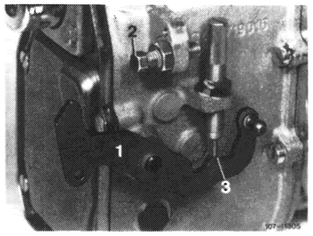
3 Check whether regulating lever (1) of injection pump rests against idle speed stop (3).
1 Regulating lever 3 Idle speed stop 2 Full throttle stop
4 Vehicles with manual transmission:
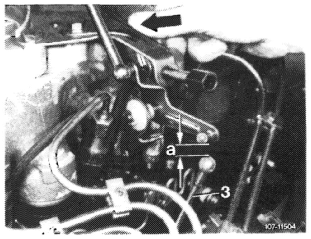
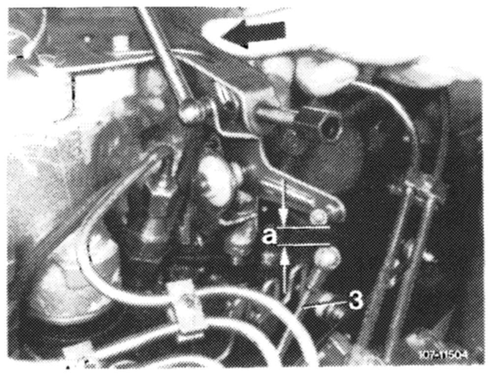
a) Adjust pull rod (3). For this purpose, push shutoff lever (arrow) to stop. Adjust pull rod in such a manner that there are 5–6 mm (distance ‘‘a’’) play between bottom edge of ball head and upper edge of ball socket. Attach pull rod.
Attention! On engine 616, pull rod (3) should be covered with an insulating hose.
3 Pull rod Distance ‘‘a’’ = 5–6 mm
b) Adjust connecting rod (1 and 2) to 122 mm or 327 mm, measured from center to center of ball head, and attach.
1 Connecting rod 2 Connecting rod
step on accelerator pedal from inside vehicle up to stop. Accelerator pedal and regulating lever (1 in Fig. item 3) should rest against full throttle stop. Adjust regulating shaft (6), if required. For this purpose, loosen hex screw (7), pull accelerator pedal slightly up and tighten hex screw again. Check full throttle stop once again and repeat adjustments, if required.
Attention!
If the regulating linkage is not moving to full throttle, check whether shaped spring (arrow) for idle speed adjuster is correctly installed.
5 Vehicles with automatic transmission:
a) Adjust pull rod (3). For this purpose, push shutoff lever (arrow) against stop. Adjust pull rod in such a manner that the play between bottom edge of ball head and upper edge of ball socket is 5–6 mm (distance ‘‘a’’). Attach pull rod.
Attention! On engine 616, pull rod (3) should be covered with an insulating hose.
3 Pull rod Distance ‘’a’’ = 5–6 mm
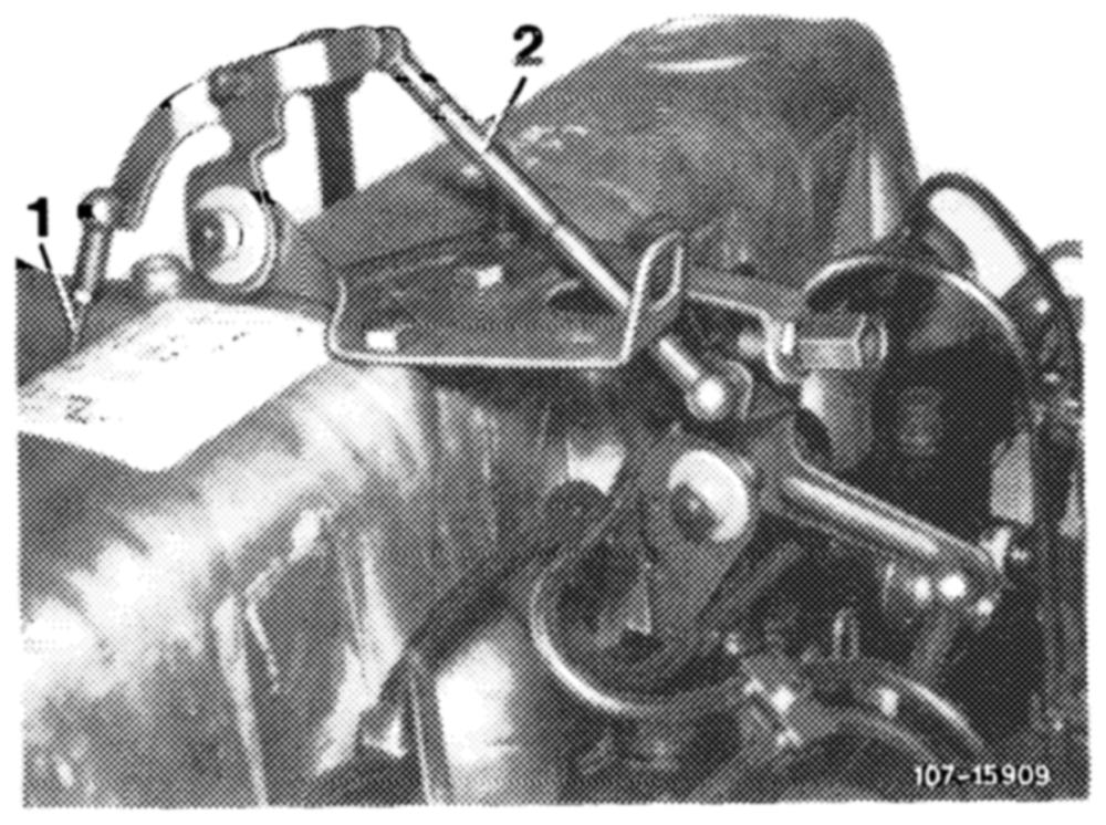
b) Adjust connecting rod (1) to 327 mm, measured from center to center of ball head, and attach.
c) Attach idle path rod (2).
1 Connecting rod 2 Idle path rod
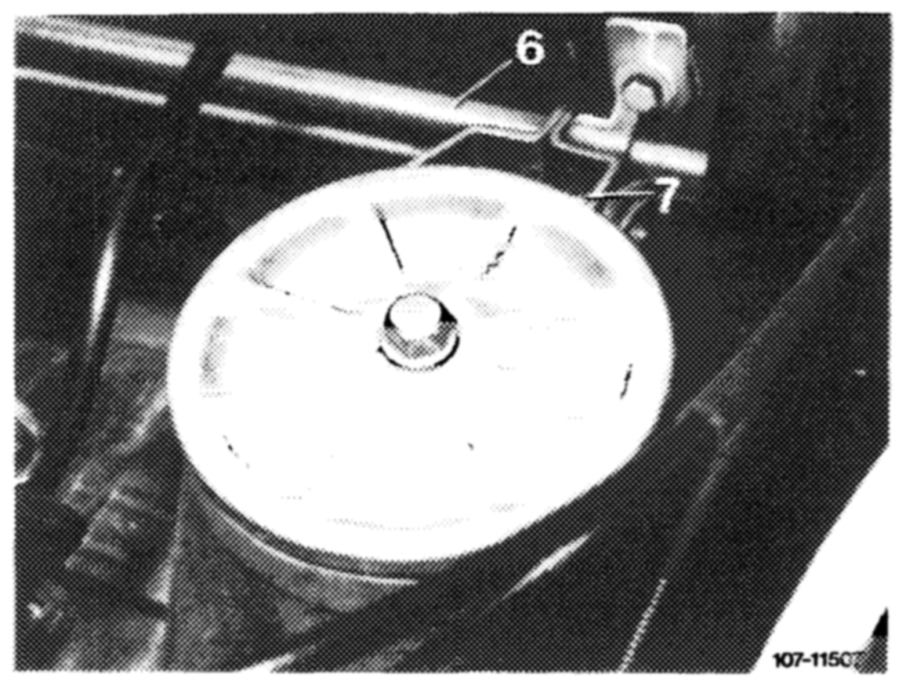
step on accelerator pedal from inside vehicle down to stop on kickdown switch. The accelerator pedal and the regulating lever (1 in Fig. item 3) should rest against full throttle stop. Adjust regulating shaft (6) if required. For this purpose, loosen hex screw (7), pull accelerator pedal slightly up and tighten hex screw again. Check full throttle stop again and repeat adjustments, if required.
Attention!
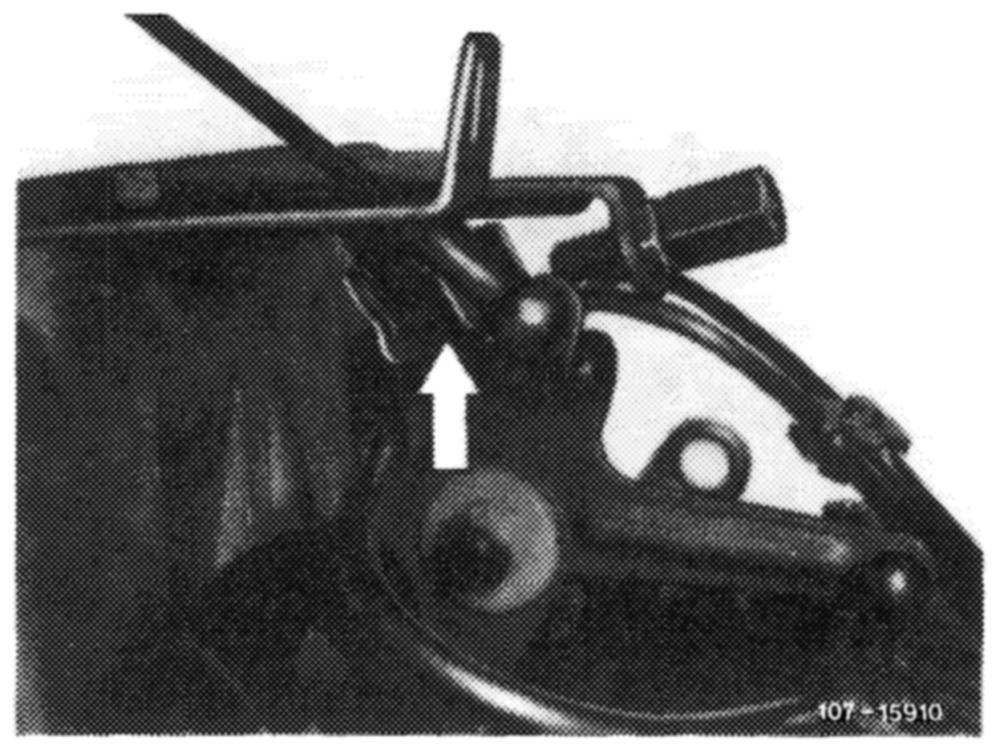
If regulating linkage is not moving to full throttle, check whether shaped spring (arrow) for idle speed adjuster is correctly installed.
e) Adjust control pressure rod.
Attention! Since the working pressure is regulated via the control pressure rod it is extremely important that it is adjusted as instructed. A wrongly adjusted control pressure rod will change the working pressures and thereby damage the gear assembly.
Engine 616
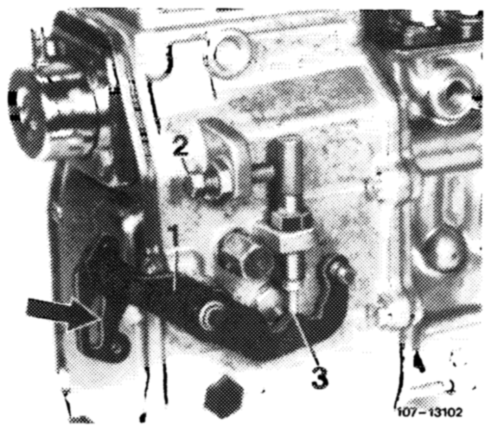
Note The control pressure rod is attached to slot (arrow) of regulating lever (1) on injection pump.
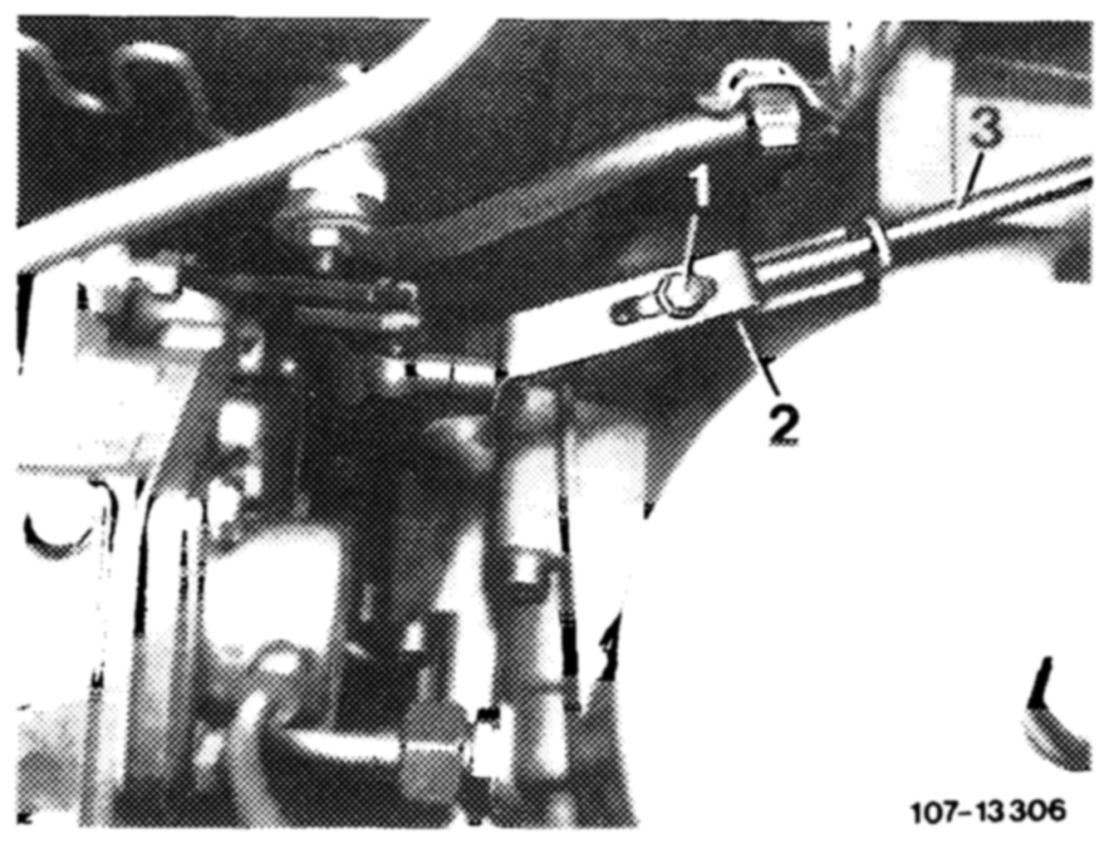
Apply full throttle from direction of guide lever on cylinder head cover. Regulating lever should rest against full throttle stop on injection pump and control pressure rod against full throttle stop of automatic transmission.
Tighten clamping screw (1) again.
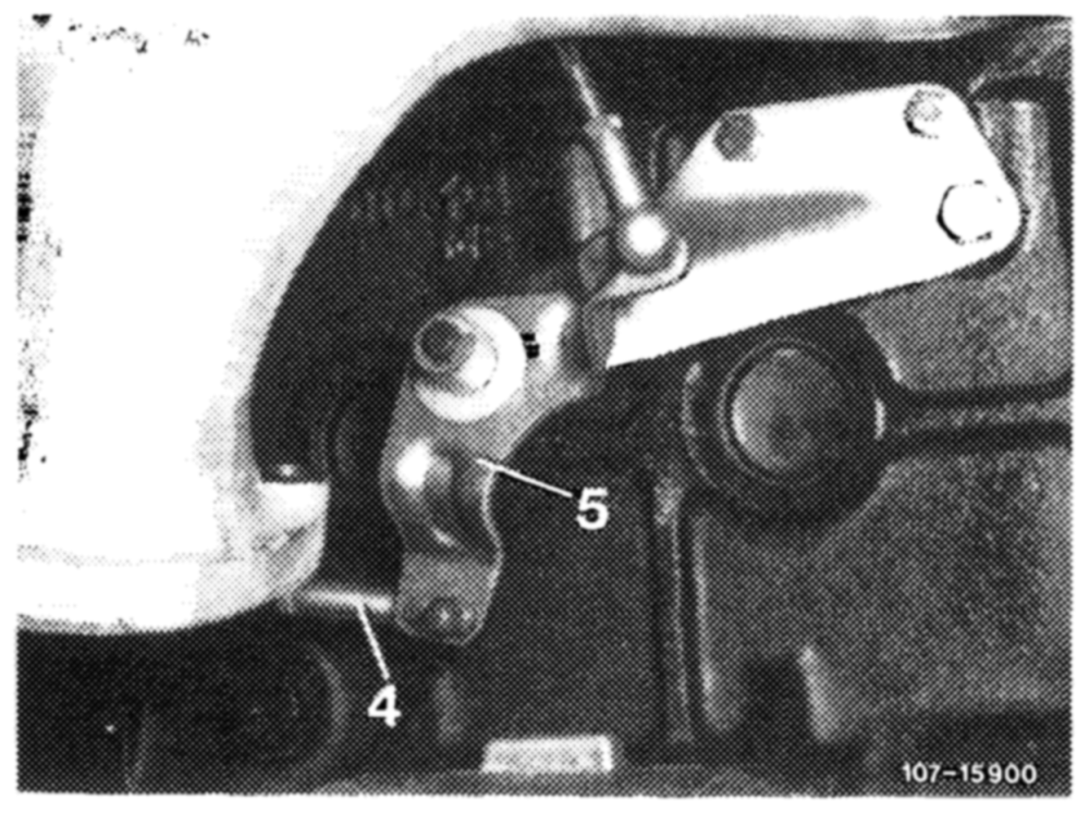
Note: Compression spring (2) pulls the control pressure rod to full throttle. 1 Clamping screw 2 Compression spring (covered) 3 Control pressure rod
Engine 617
Disconnect contro! pressure rod (4) and apply full throttle from direction of guide lever (5). Pull control pressure rod completely forward to full throttle stop and attach free of tension, adjust if required.
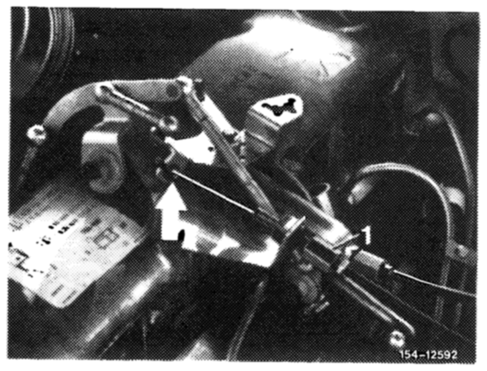
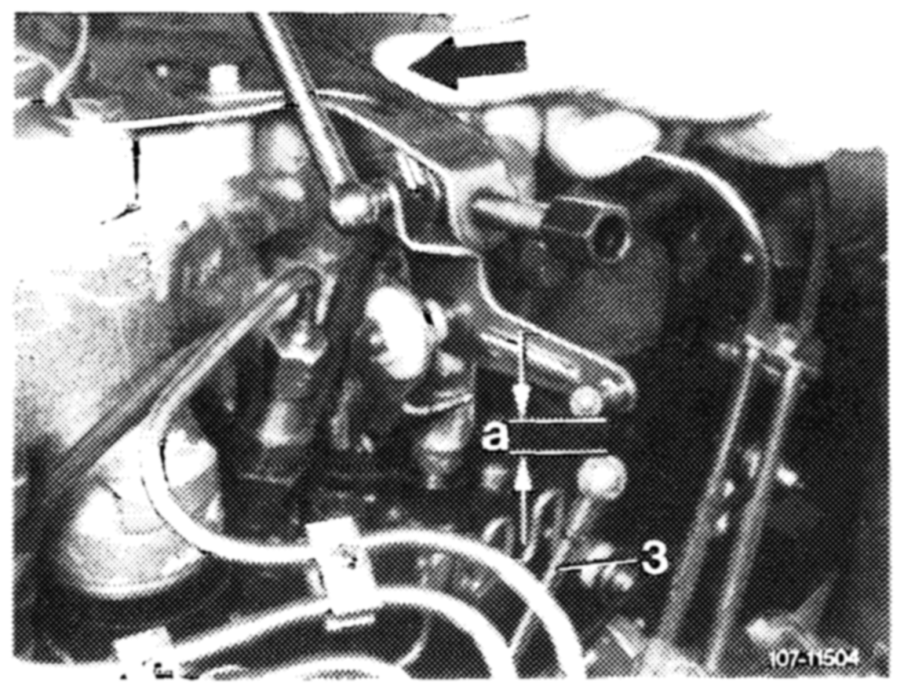
f) Adjust Bowden wire for Tempomat (cruise control). For this purpose, push shutoff lever up to stop position. Bowden wire should rest against regulating lever (arrow). Adjust Bowden wire with adjusting screw (1), if required. Release shutoff lever (idle speed position). In this position, Bowden wire is slack.
6 Check function of emergency stop button. Run engine at idle speed, push emergency stop button (arrow). Engine should shut off. Readjust pull rod (3), if required.
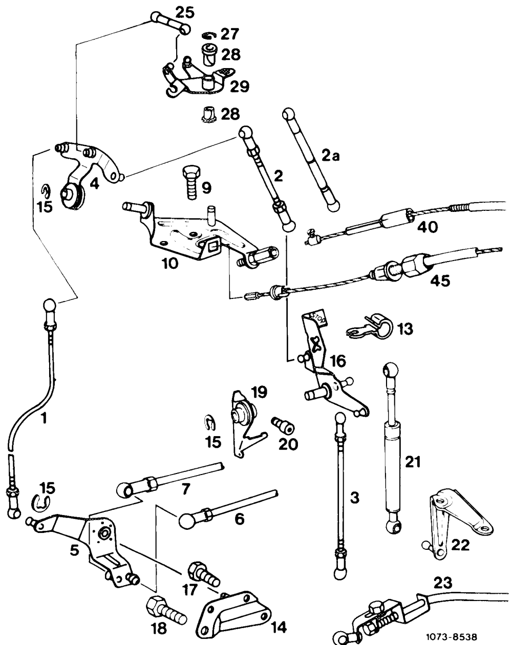
MWinjection pump with mechanical governor
1 Push rod 13 Shaped spring 23 Control pressure rod engine 616
2 Connecting rod 14 Bearing 40 Bowden wire for idle speed adjuster 2a Idle path rod 15 Lock 45 Bowden wire for Tempomat
3 Pull rod 16 Angle lever (cruise control)
4 Guide lever 17 Hex screw
5 Intermediate lever 18 Hex screw USA version
6 Connecting rod to front 19 Bearing 25 Connecting rod wall regulating shaft 20 Hex socket screw 27 Lock
7 Control pressure rod engine 617 21 Damper 28 Plastic bushing
9 Hex screw 22 Holder 29 Guide lever
10 Holder
Designation Engine mm
616, 617 180 Push rod (4 in Fig. item 2) 615 188
Connecting rod (5 in Fig. item 2) 615, 616, 617 213
Adjusting
1 Check regulating linkage for easy operation and distortions. Replace damaged parts, if any.
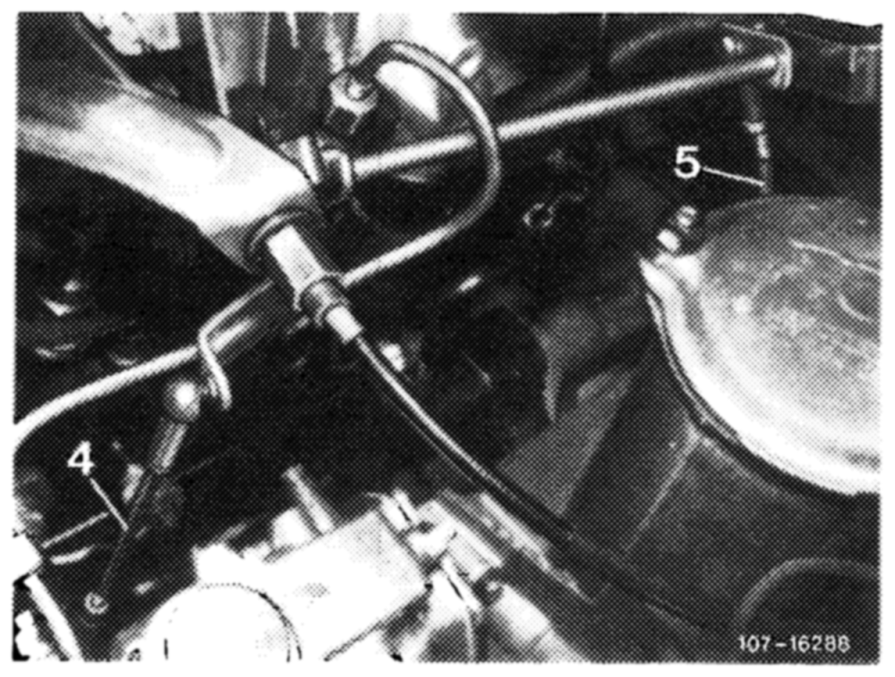
2 Disconnect both regulating rods (4 and 5).
3 Set push rod (4) on engine 615 to 188 mm, on engine 616 and 617 to 180 mm, measured from center to center of ball socket and attach.
Attention! On engine 617, the push rod (4) should be covered with an insulating hose.
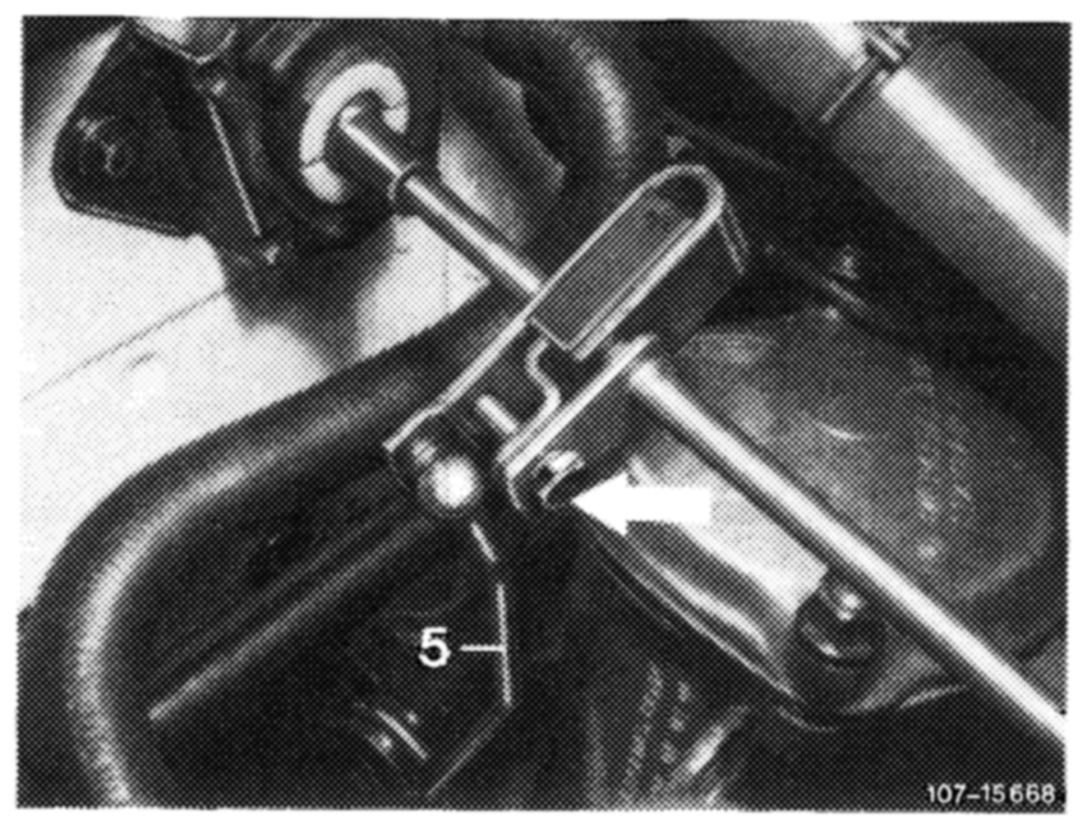
4 Check full stop position. With engine stopped, step on accelerator pedal from inside vehicle down to stop or on automatic transmission down to stop of kickdown switch. Accelerator pedal and regulating lever should rest against full throttle stop (2). If required, adjust regulating linkage with adjusting screw (arrow) in such a manner that the regulating lever on injection pump (1) rests against full throttle stop (2).
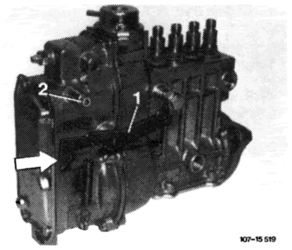
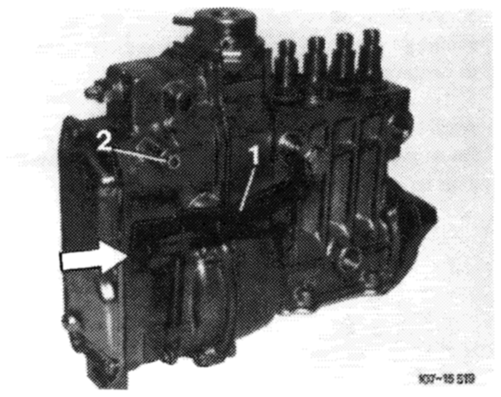
If the full throttle or idle throttle stop is not attained with this adjustment, adjust connecting rod (5) from longitudinal regulating valve to accelerator pedal to 213 mm, measured from center of ball socket to center of damping ring and attach.
6 Vehicles with automatic transmission. Adjust control pressure rod as follows:
Engine 616 1st version
The contro! pressure rod is attached to bore (arrow) of regulating lever (1) on injection pump.
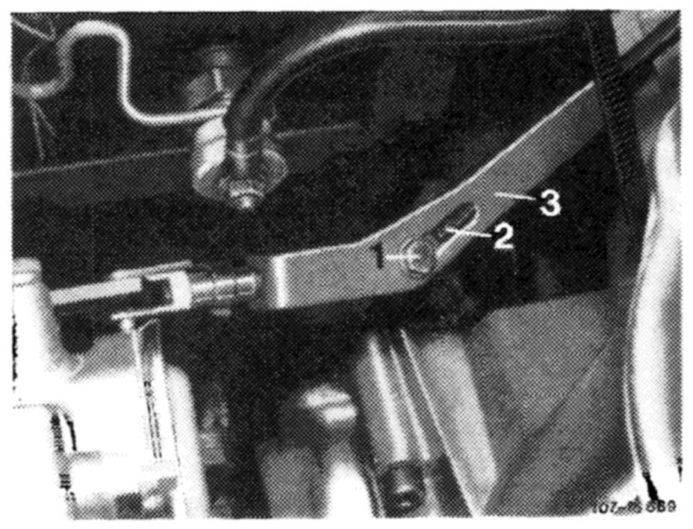
Loosen clamping screw (1) oncontrol pressure rod (3). Apply full throttle from direction of guide lever on cylinder head cover. Regulating lever should rest against full throttle stop on injection pump and the control pressure rod against full throttle stop of automatic transmission.
Note: Compression spring (2) will pull contro! pressure rod also to full throttle.
Engine 615, 617
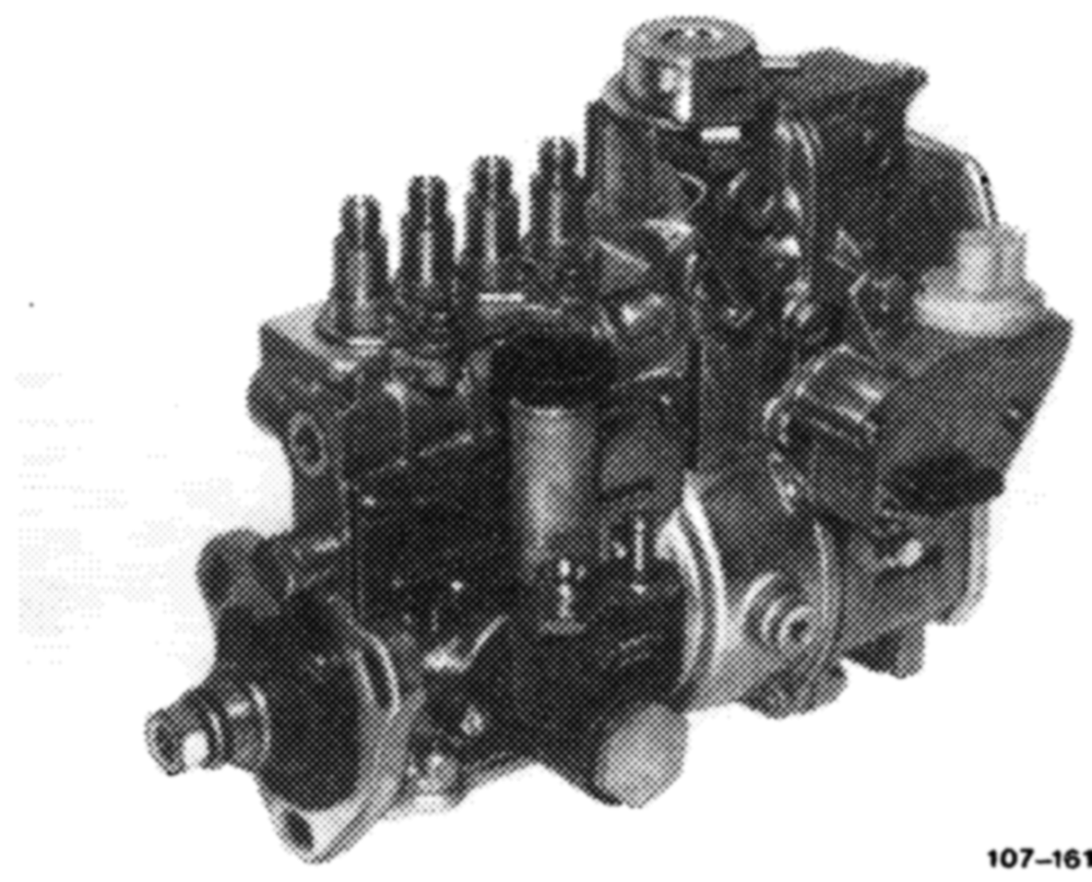
Engine 616 2nd version
Note: These engines have no control pressure rod. A vacuum control valve is mounted to injection pump instead.
Start of series
Starting Starting Model Engine = engine chassis end No. end No. automatic transmission
123.120 615.940 004749 146687
123.102 123.103 123.193 016-912 027799 109714 123.125
123.183 003661
123.105 123.130 165193 123.132 165258 617.912 085716 123.150 004950 123.190 011087
Length of regulating linkage
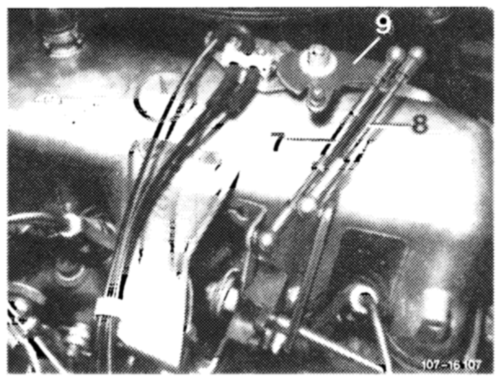
Idle path rod (7) in extended condition 54 mm 154
Pull rod (8) 137 mm
1 Disconnect all regulating rods.