2 Adjust vacuum control valve. For this purpose,
WIS 30-300-2
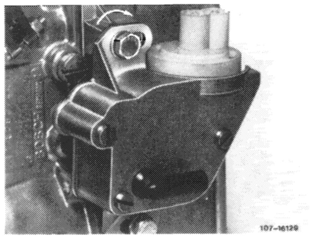
loosen fastening screws. Push regulating lever of injection pump to full load and turn vacuum control valve clockwise (arrow) up to noticeable stop. In this position, tighten fastening screws again.
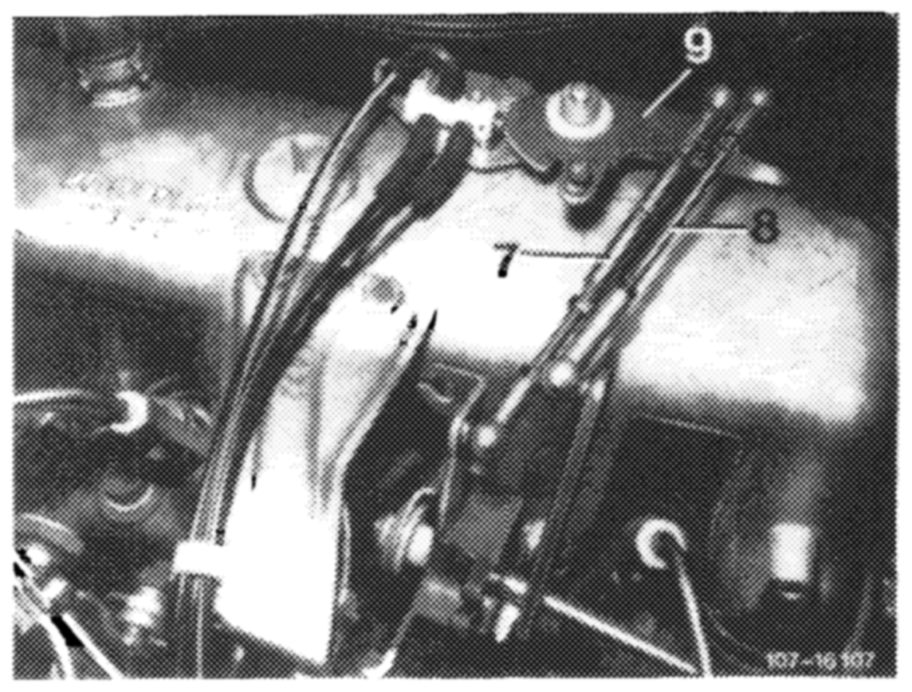
3 Adjust and attach idle path rod (7) in fully extended condition and pull rod (8) to 137 mm, measure from center to center of ball head.
7 Idle path rod 8 Pull rod
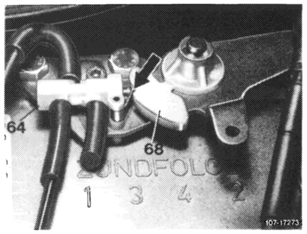
4 Adjust push rod (4) in such a manner that max. 0.5 mm play (refer to arrow) is available between control cam lobe of guide lever (68) and link of switchover valve (64). Regulating lever on injection pump should rest against idle speed stop, and idle path rod (7) should be completely extended.
Attention! Do not actuate switchover valve in this position.
64 Switchover valve 68 Guide lever
Attention!
During lubricating jobs for regulating system, do not lubricate runway of plastic cam on guide lever.
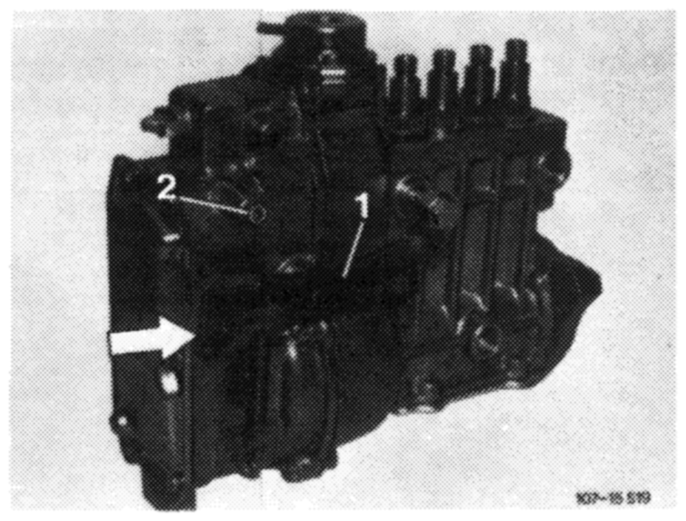
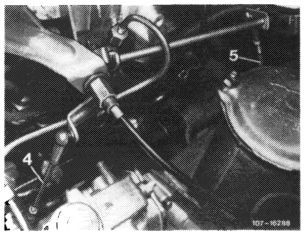
on accelerator pedal from inside vehicle down to stop of kickdown switch. Accelerator pedal and regulating lever should rest against full throttle stop (2). If required, adjust regulating linkage with adjusting screw (arrow) in such a manner that the regulating lever on injection pump (1) rests against full throttle stop (2).
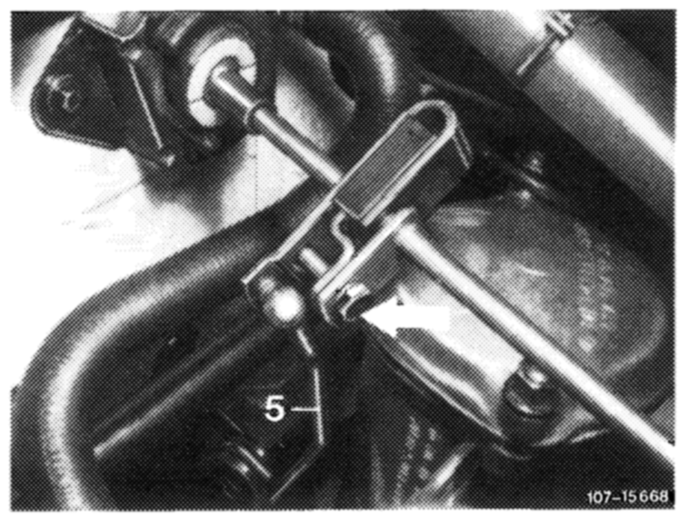
If the full throttle or idle speed stop is not attained with this adjustment, adjust connecting rod (5) from longitudinal regulating shaft to accelerator pedal to 213 mm, measured from center of ball socket to center of damping ring and attach.
Engine 615, 616, 617 in model 123.1 with manual! transmission
M/RSF-injection pump with mechanical governor
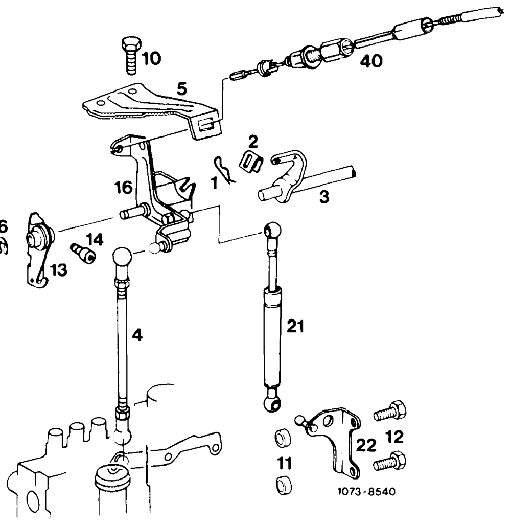
1 Lock 6 Lock 14 Hex socket screw
2 Eve 10 Hex screw 16 Angle lever 3 > Longitudinal regulating shaft 11. Spacing ring 21 Damper
4 Push rod 12 Hex screw 22 Holder
5 Holder 13 Bearing 40 Bowden wire for idle speed adjuster
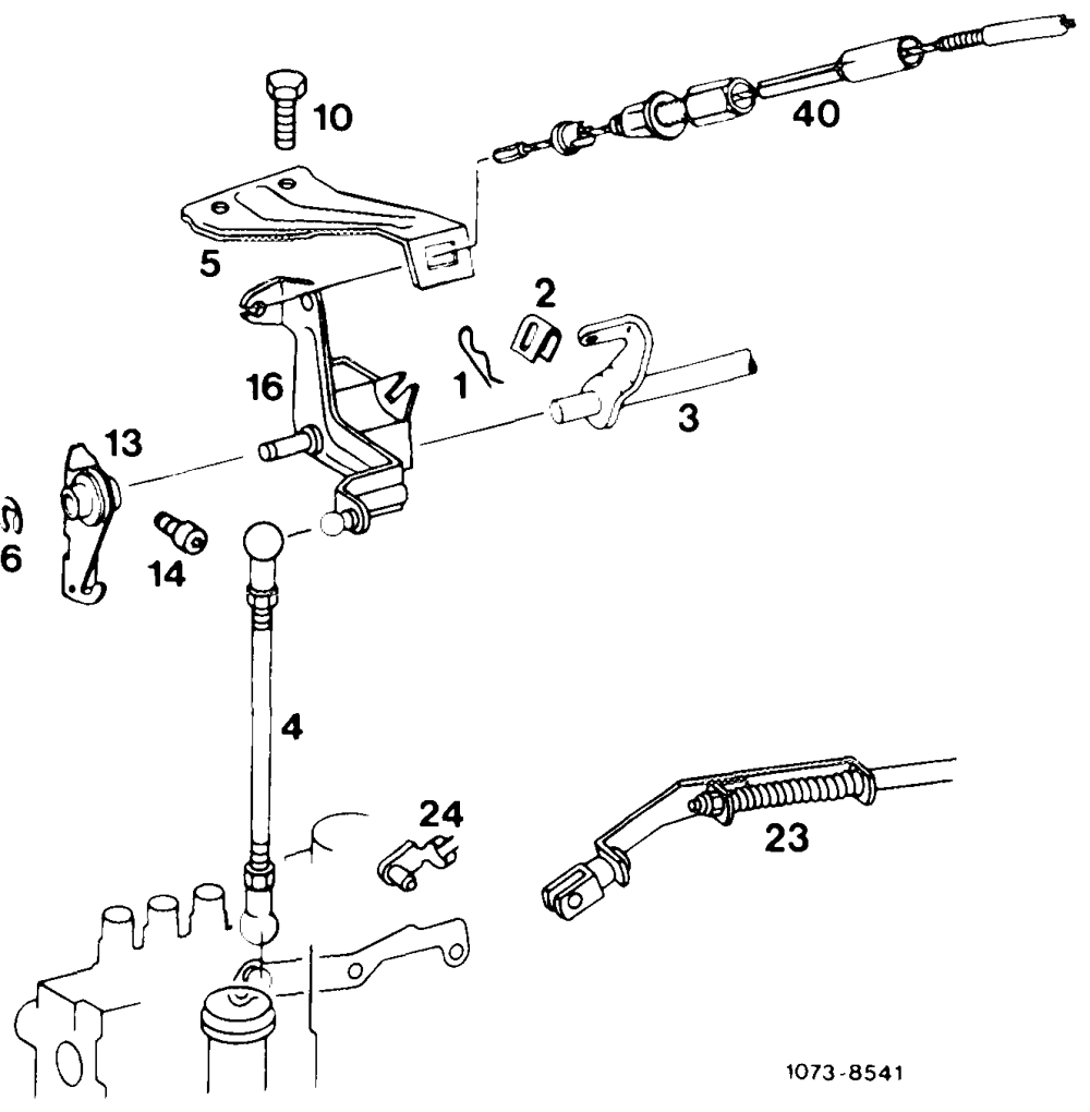
Engine regulation Engine 616 in model 123.1 with automatic transmission 1st version M/RSF-injection pump with mechanical governor
1 Lock 6 Lock 23 Control pressure rod
2 Eye 10 Hex screw 24 Lock for control pressure rod
3 Longitudinal regulating shaft 13 Bearing 40 Bowden wire for idle speed adjuster
4 Push rod 14 Hex socket screw
5 Holder 16 Angle lever
Engine 615, 616, 617 in model 123.1 with automatic transmission 2nd version
M/RSF-injection pump with mechanical governor
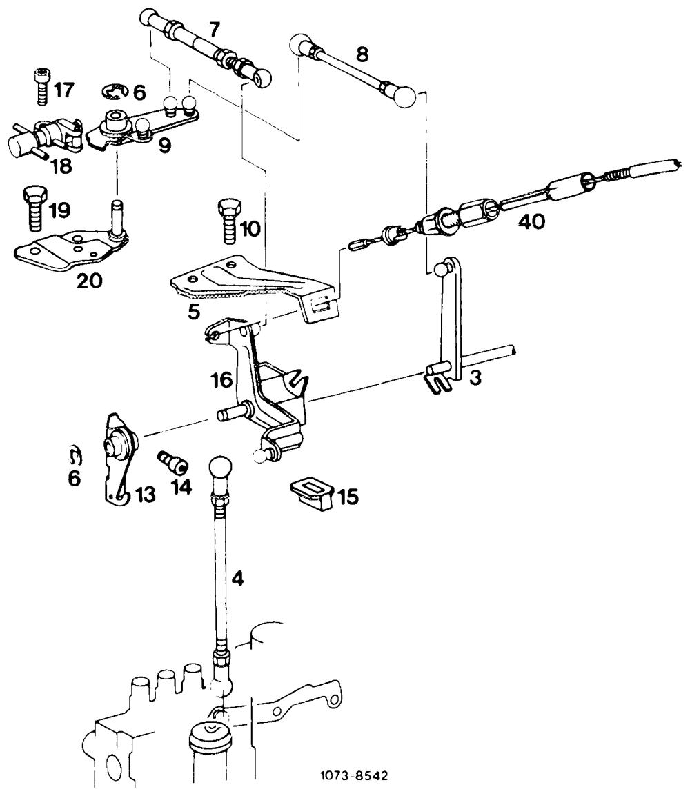
3 Longitudinal regulating shaft 9 Guide lever 17 Hex socket screw
4 Push rod 10 Hex screw 18 Vacuum control valve
5 Holder 13 Bearing 19 Hex screw
6 Lock 14 Hex socket screw 20 Bearing
7 Idle path rod 15 Plastic hub 40 Bowden wire for idle speed adjuster
8 Pull rod 16 Angle lever shaft model 115.1
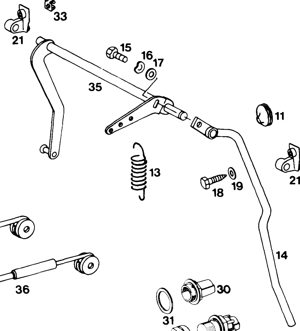
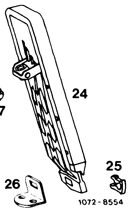
Engine 615, 616 with M-injection pump, Engine 617 with MW- injection pump
we
11. Rubber grommet Bearing 30 Full throttle stop 13. Return spring Gasket 31 Washer
14 Accelerator pedal Accelerator pedal 33 Cage nut Clip
15 Hex screw 35 Front wall regulating shaft Fastening plate
16 Domed washer 36 Resilient connecting rod
17 Washer Joint 36a Rigid connecting rod
18 Hex screw Kickdown switch Adjusting nut
19 Domed washer
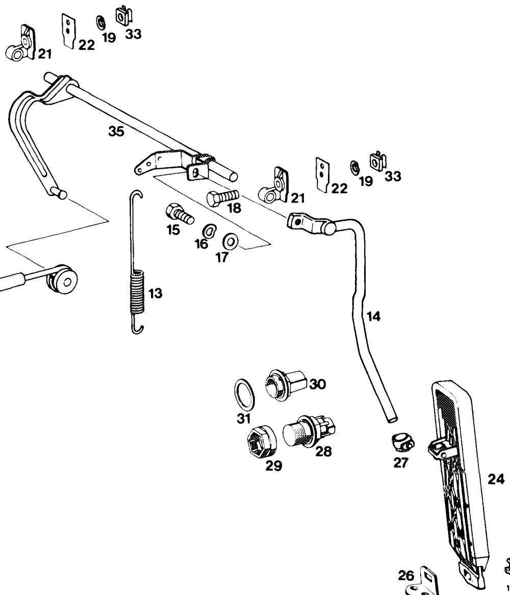
Engine 615, 616 with M-injection pump, Engine 616, 617 with MW-injection pump
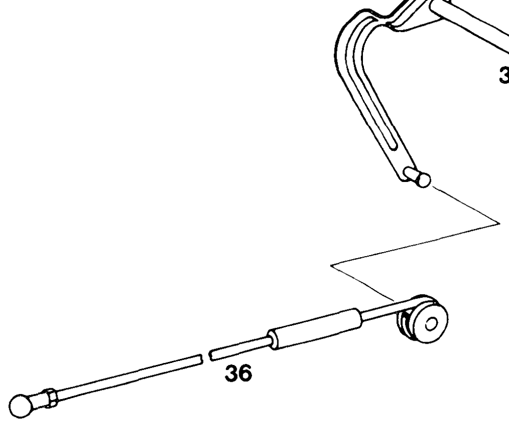
os
Q25
13 Return spring 21 + Bearing 29 Adjusting nut
14 Accelerator lever 22 Gasket 30 Full throttle stop
15 Hex screw 24 Accelerator pedal 31. Washer
16 Domed washer 25 Clip 33 Cage nut
17 Washer 26 Fastening plate 35 Front wall regulating shaft
18 Hex screw 27 Joint 36 Resilient connecting rod
19 Domed washer 28 Kickdown switch
Engine 615, 616, 617 with M/RSF-injection pump
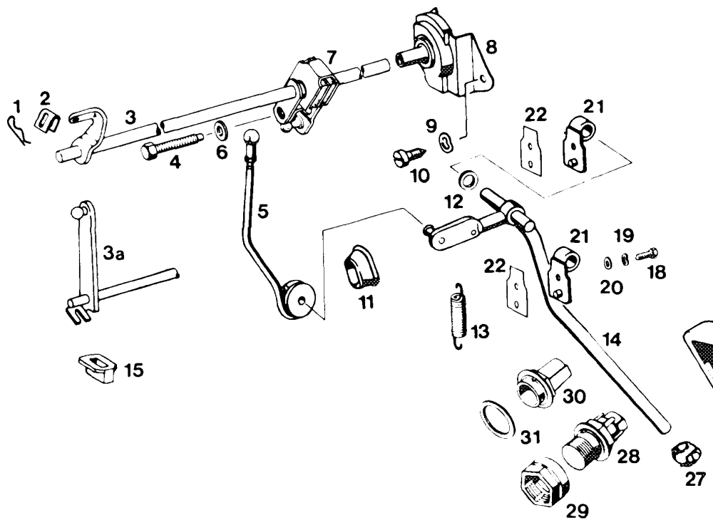
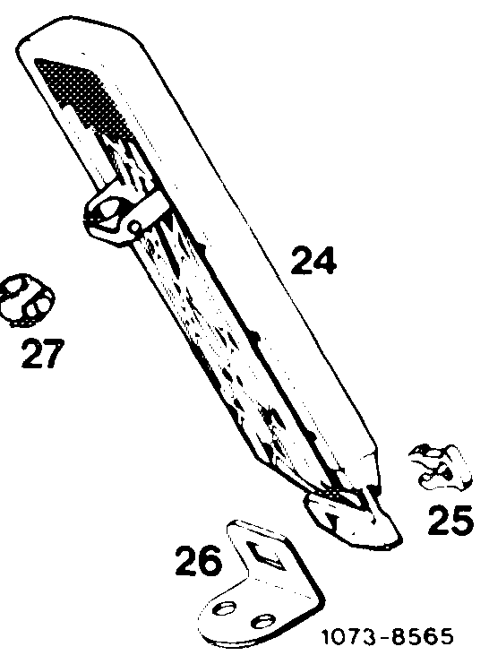
1 Lock, manual transmission 10 Screw 22 Gasket 2. Spring, manual transmission 11 Rubber grommet 24 Accelerator pedal
3 Longitudinal regulating shaft manual transmission 12 Plastic spacing ring 25 Clip 3a Longitudinal regulating shaft automatic transmission 13 Return spring 26 Fastening plate ODrIHDnILS Adjusting screw 14 Accelerator lever 27 Joint Push rod 15 Plastic hub 28 Kickdown switch Washer 18 Hex screw 29 Adjusting nut Angle lever with damper 19 Domed washer 30 Full throttle stop Bearing for regulating shaft 20 Washer 31 Washer Domed washer 21 Bearing
Chassis regulation with longitudinal regulating shaft 2nd version
Model 123.1
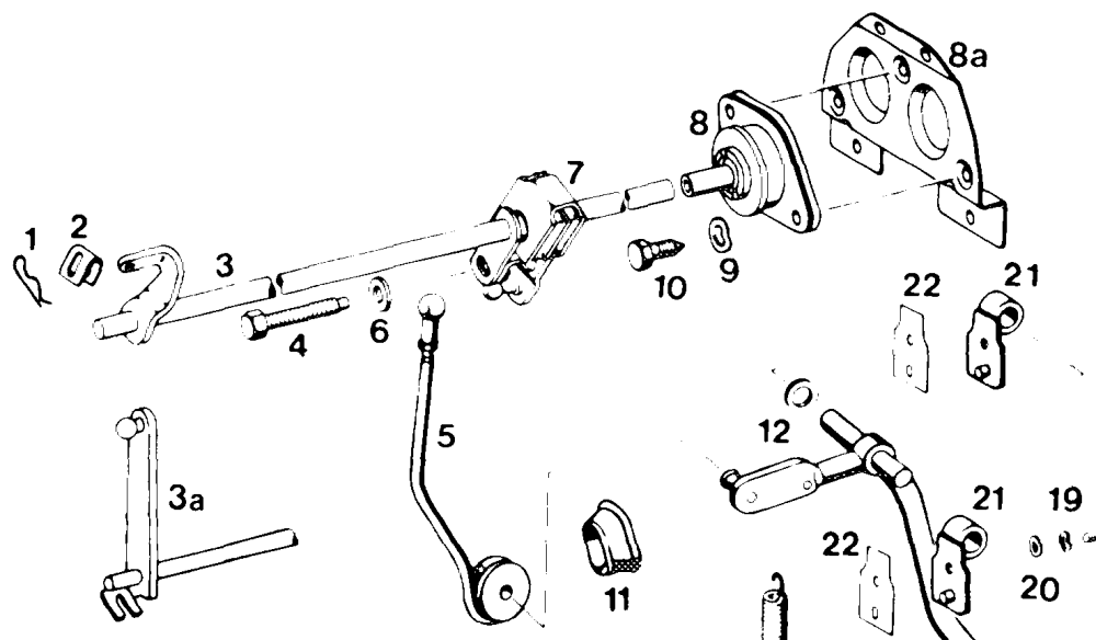
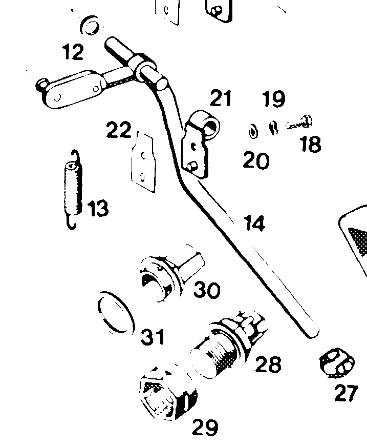
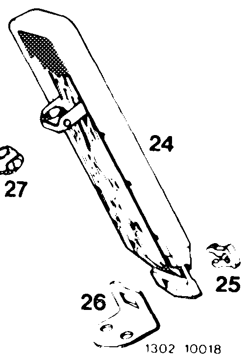
Engine 615, 616, 617 with M/RSF-injection pump
1 Lock, manual transmission 10 Screw 25 Clip
2 Spring, manual transmission 11. Rubber grommet 26 Fastening plate
3 Longitudinal regulating shaft, 12 Plastic spacing ring 27 = = Joint manual transmission 13. Return spring 28 Kickdown switch 3a Longitudinal regulating shaft, 14 Accelerator lever 29 Adjusting nut automatic transmission 15 Plastic hub 30 Full throttle stop
4 Adjusting schrew 18 Hex. screw 31. Washer
5 Push rod 19 Domed washer
6 Washer 20 Washer
7 Angle lever with damper 21° Bearing
8 Bearing for regulating shaft 22 Gasket 8a Plate 24 Accelerator pedal
9 Domed washer
Model 123.1
Engine 615, 616, 617 with M/RSF-injection pump
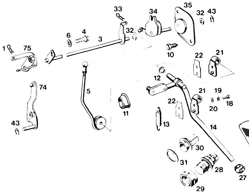
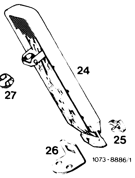
18 29 Adjusting nut Lock, manual transmission Hex. screw OnhwFull throttle stop Longitudinal regulating shaft 19 Domed washer 30 Adjusting screw 20 Washer 31 Washer Push rod 32 Plastic spacing ring 21 Bearing Washer 22 Gasket 33 Lock 10 Screw 24 Accelerator pedal 34 Regulating lever with dampfer Clip 35 Bearing holder 11 Rubber grommet 25 Fastening plate Plastic spacing ring 26 43 Lock Guide lever, automatic transmission 13 Return spring 27 Joint 74 14 Accelerator lever 28 Kickdown switch 75 Driver, manual transmission
Length of regulating linkage
Idle path rod (60 in Fig. item 8) in extended condition 154 mm
Pull rod (61 in Fig. item 8) 137 mm
Push rod (5 in Fig. item 6) 186 mm
Connecting rod (5 in Fig. item 7) 122 mm
Adjustment
1 Check regulating linkage for easy operation and distortion. Replace damaged parts, if required.
2 Disconnect all regulating rods.
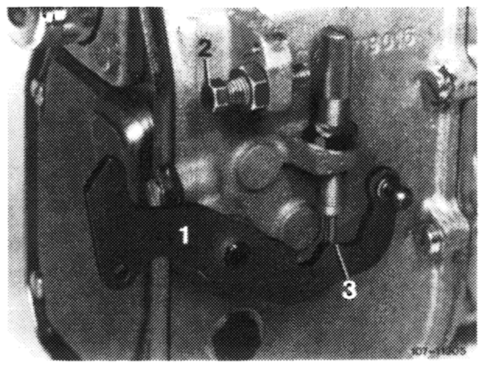
3 Check whether regulating lever (1) of injection pump rests against idle speed stop (3).
1 Regulating lever 2 Full throttle stop 3 Idle speed stop
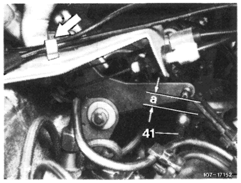
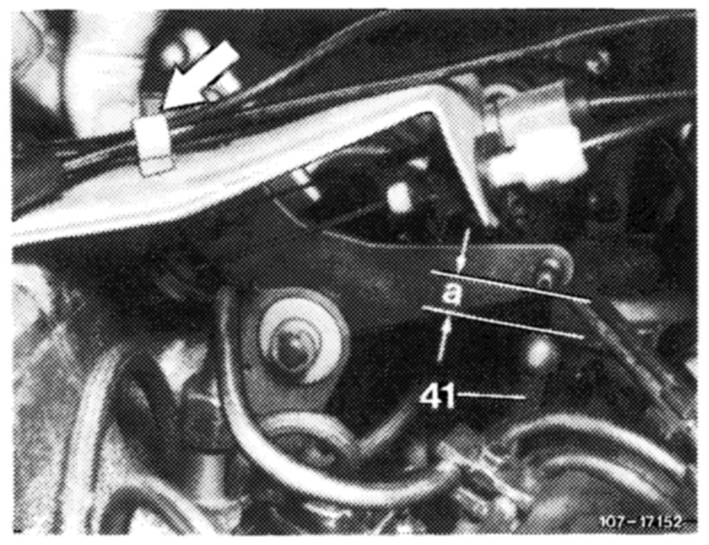
Attention! On engine 616, push rod (41) should be covered with an insulating hose.
Vehicles with manual transmission
4 Adjust push rod (41). For this purpose, push shutoff lever (arrow) against stop. Adjust push rod in such a manner that 5—6 mm clearance (distance “‘a”) is available between bottom edge of ball head and upper edge of ball socket. Attach push rod.
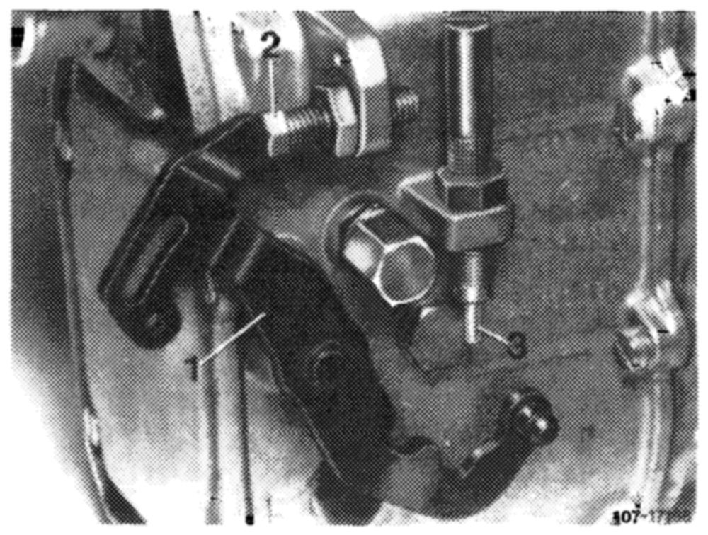
on accelerator pedal from inside vehicle down to stop. Accelerator pedal and regulating lever (1) should then rest against full load stop of injection pump (2). If required, adjust regulating linkage by means of adjusting screw in such a manner that the regulating lever rests against full throttle stop (2) on injection pump (1).
1 Regulating lever 2 Full throttle stop 3 Idle speed stop
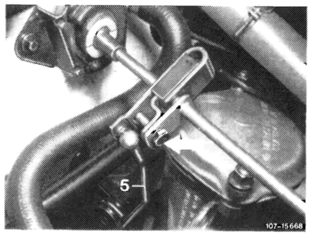
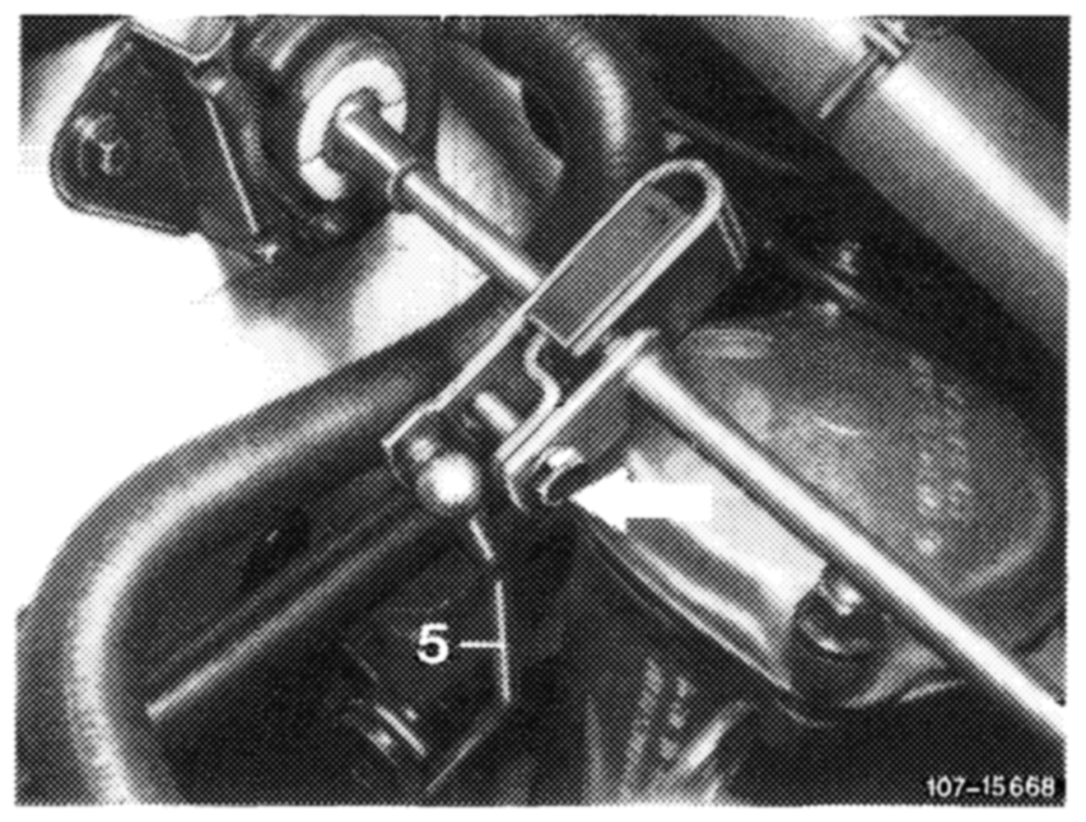
6 If full throttle or idle speed stop (3) is not attained with this adjusting screw, adjust push rod (5) from longitudinal regulating shaft to accelerator pedal to 186 mm, measured from center of ball socket to center of damping ring.
Attention!
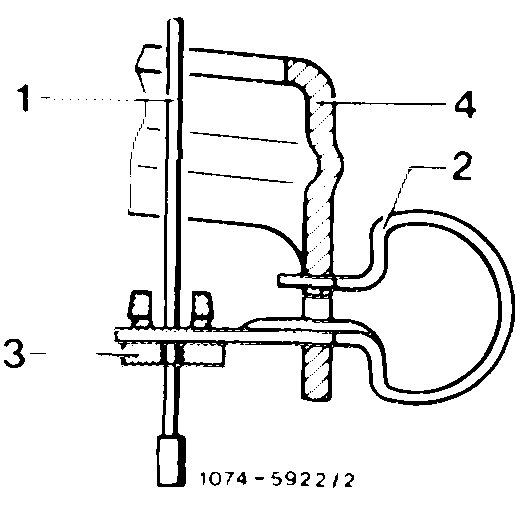
\f the regulating linkage is not moving to full throttle, check whether contour spring for idle speed adjuster is correctly installed.
Cable contro! for idle speed increase PBwnContour spring Plastic scleeve Guide lever
Vehicles with automatic transmission
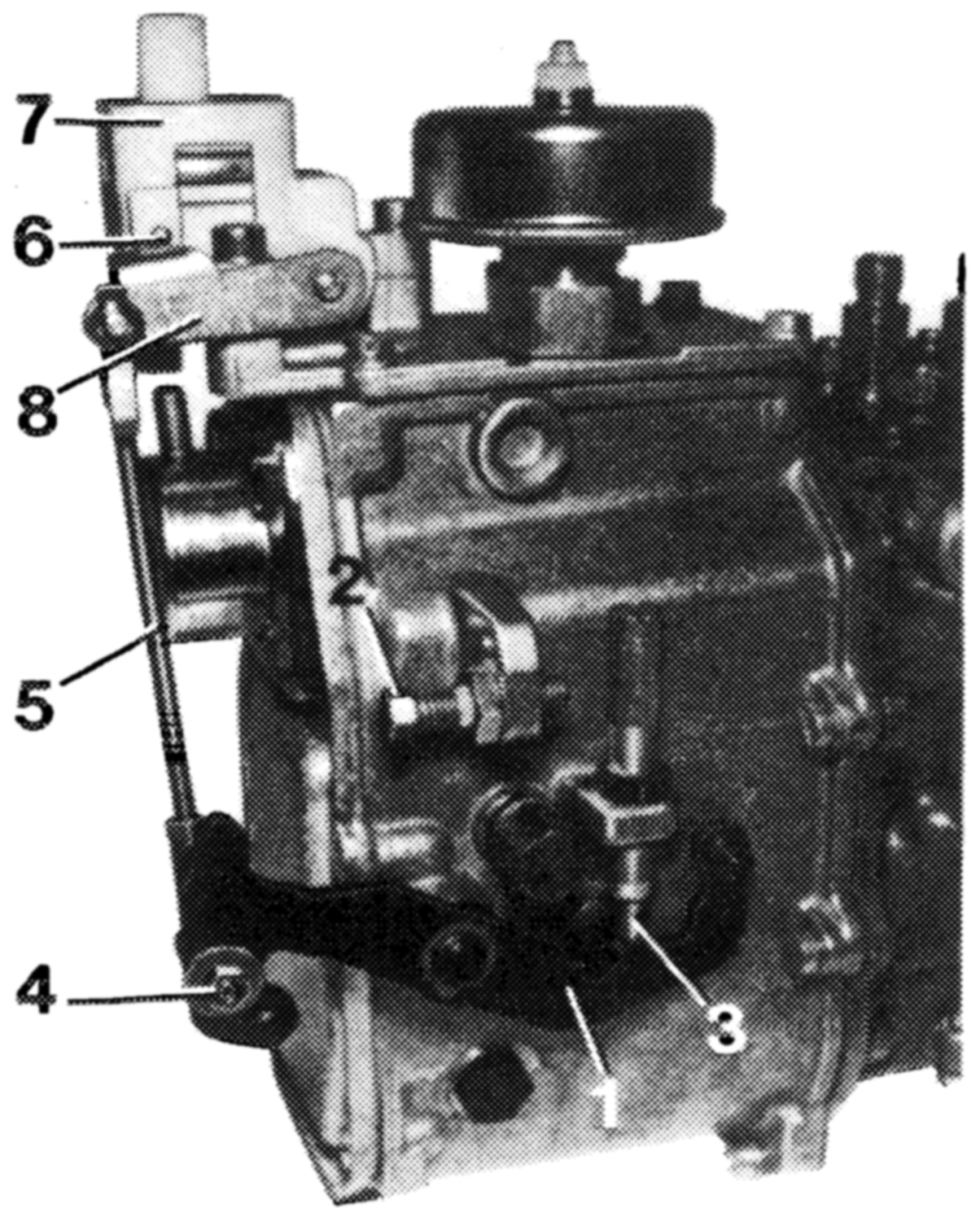
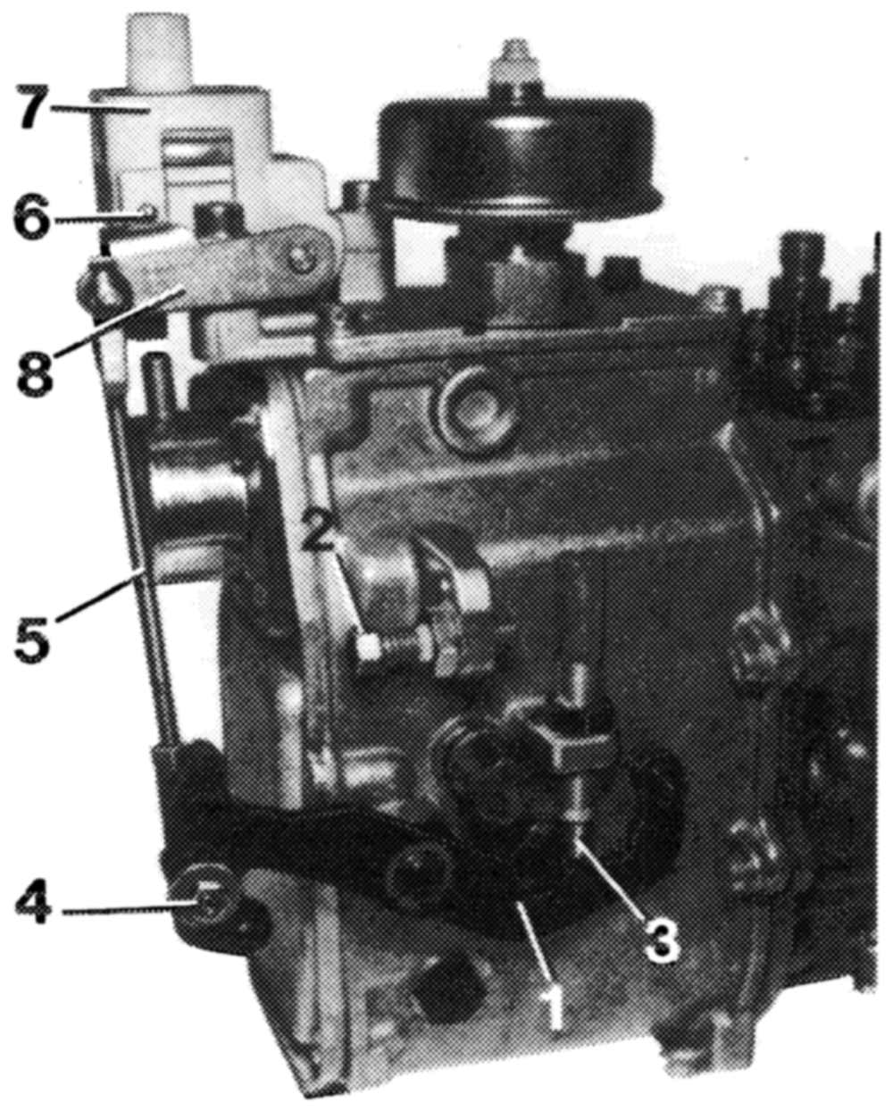
7 Check whether connecting rod (5) is correctly adjusted. For this purpose, push regulating lever (1) to full throttle stop (2). The actuating lever (8) should have max. 0.5 mm play up to full load stop (6). If required, adjust connecting rod (5) by means of adjustable ball head (4). Set connecting rod (5) to 122 mm, measured from center of ball socket to center of linkage. Attach connecting rod.
Regulating lever MOIOnRWN— Full throttle stop Idle speed stop Adjustable ball head Connecting rod Full load stop on vacuum control valve Vacuum control valve Actuating lever for vacuum control valve 107 -17189
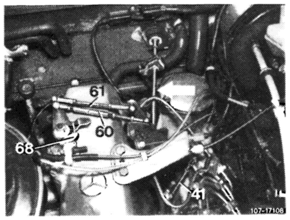
8 Adjust idle path rod (60) in fully extended condition and pull rod (61) to 137 mm, measured from center to center of ball head. Attach pull rod (61).
41 Push rod 60 Idle path rod 61 Pull rod
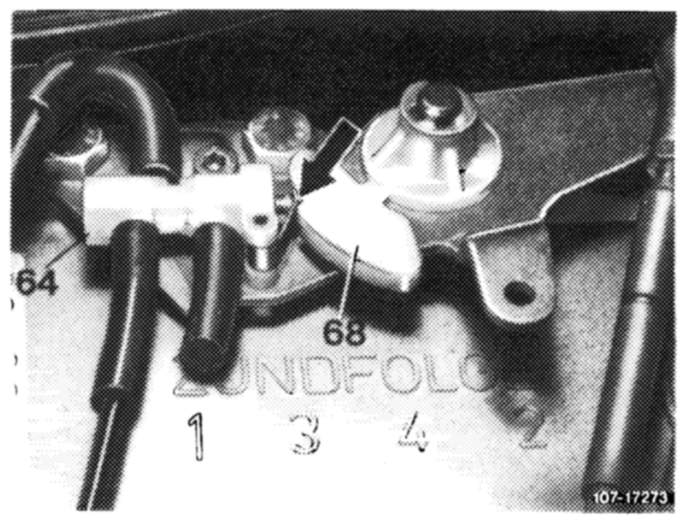
9 Adjust push rod (41) in such a manner that max. 0.5 mm play is available between control cam lobe of guide lever (68) and link of switch-over valve (64) (arrow). Regulating lever (1) should rest against idle speed stop (3).
Attention!
During lubricating jobs for regulating system, do not lubricate runway of plastic cam on guide lever.
1 Regulating lever 2 Full load stop 3 Idle speed stop 4 Adjustable ball head 5 Connecting rod 6 Full load stop on vacuum control valve 7 Vacuum control valve 8 Actuating lever for vacuum control valve
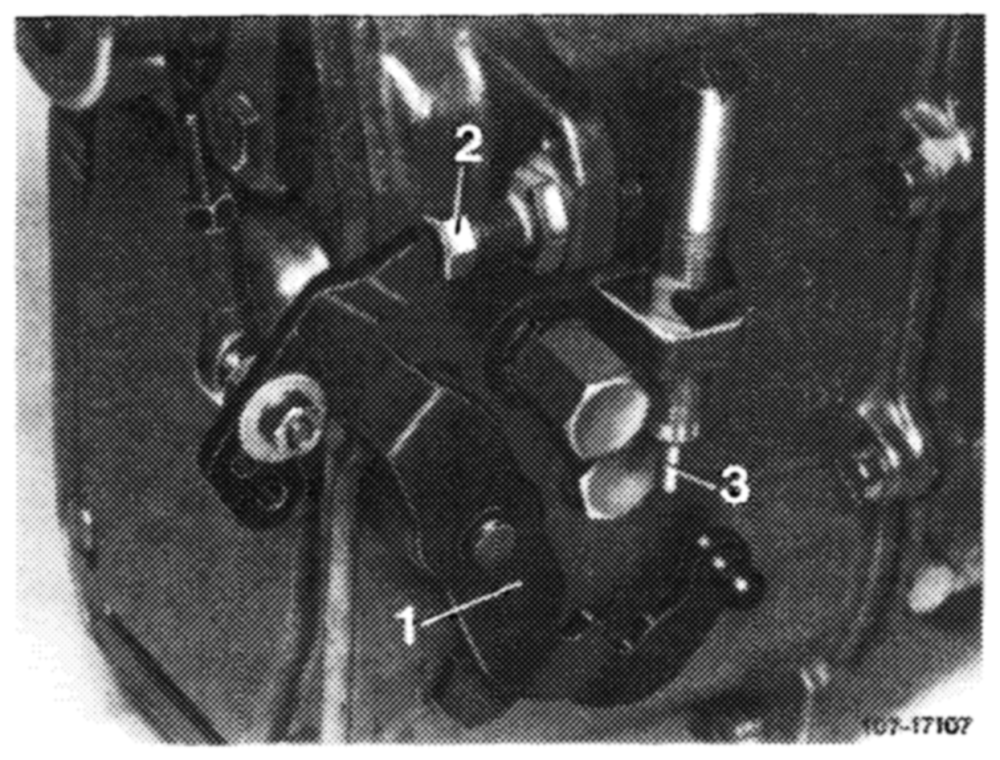
step on accelerator pedal from inside vehicle up to stop on kickdown switch. Accelerator pedal and regulating lever (1) should then rest against full throttle stop of injection pump (2). If required, adjust regulating linkage with adjusting screw (arrow) in such a manner that the regulating lever rests against full throttle stop (2) on injection pump (1).
1 Regulating lever 2 Full throttle stop 3 Idle speed stop
Attention!
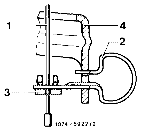
If regulating linkage is not moving to full throttle, check whether contour spring for idle speed adjuster is correctly installed.
Cable control for idle speed increase PWN Contour spring Plastic sleeve Guide lever
Engine 616 in model 123.1
MW-injection pump with mechanical governor
@® 1980
Vehicles with manual transmission
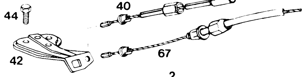
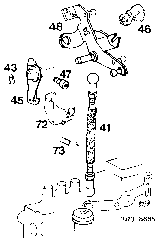
1 Lock
42 Holder 48 Angle lever
2 Spring 43 Fuse Bowden wire for idle speed adjuster
3 Longitudinal regulating 44 Hex. screw 50 Plastic bushing shaft, manual transmission 45 Bearing 67 Bowden wire for cruise contro!/Tempomat
0 Plastic sleeve 46 Contour spring 72 Holder
1 Push rod 47 Hex. socket screw 73 Hex. socket screw
Engine 616, 617 in model 123.1 MWinjection pump with mechanical governor @ 1980
Vehicles with automatic transmission
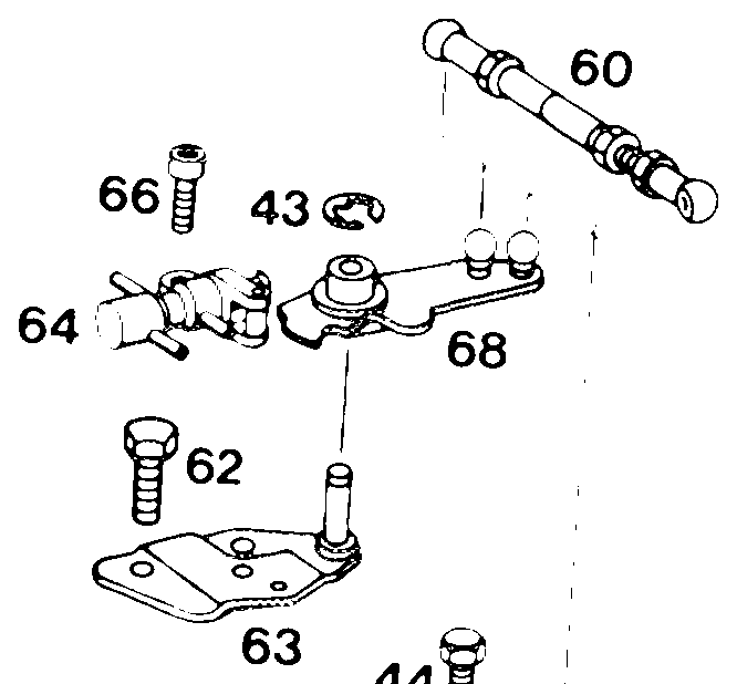
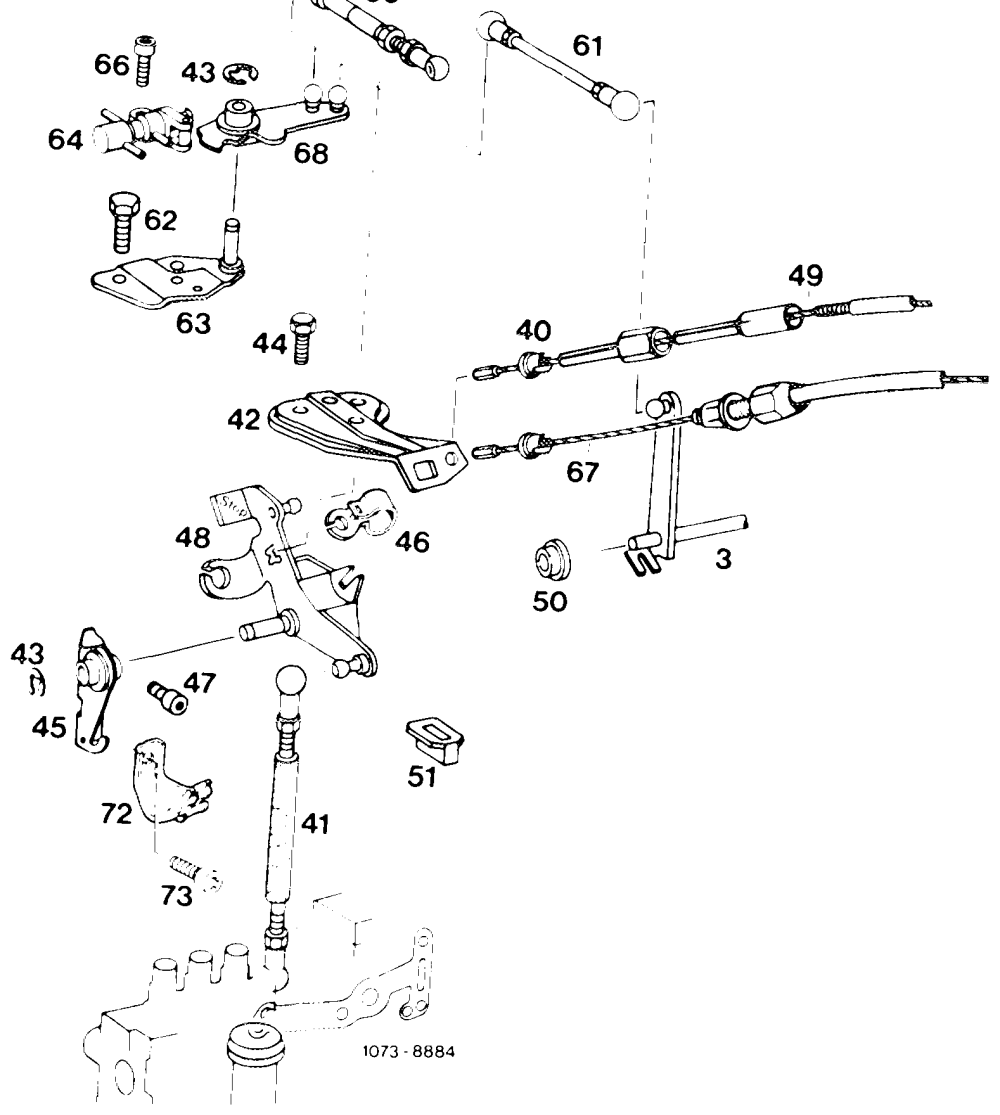
Holder Longitudinal regulating shaft Hex. socket screw 63 47 Switchover valve Plastic sleeve 48 Angle lever 64 Push rod 49 Bowden wire for idle speed 66 Hex. socket screw adjuster 67 Bowden wire for cruise control/Tempomat Holder Guide lever Plastic bushing 68 Lock 50 Hex. screw Plastic hub 72 Holder Bearing 60 Idle path rod 73 Hex. socket screw Contour spring 61 Pull rod 62 Hex. screw
Lenght of regulating linkage
Idle path rod (60 in Fig. item 9) in extended condition 154 mm
Pull rod (61 in Fig. item 9) 137 mm
Push rod (5 in Fig. item 6) 186 mm
Connecting rod (5 in Fig. item 8) 122 mm
Adjustment
1 Check regulating linkage for easy operation and distortion. Renew damaged parts, if required.
2 Disconnect all regulating rods.
3 Check whether regulating lever (1) of injection pump rests against idle speed stop (3).
Attention!
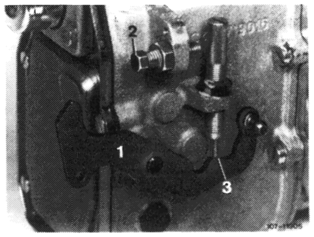
Push rod (41) should be covered with an insulating hose.
1 Regulating lever 2 Full throttle stop 3. Idle speed stop
Vehicles with manual transmission
4 Adjust push rod (41). For this purpose, push shutoff lever (arrow) against stop. Adjust push rod in such a manner that a clearance of 5—6 mm (distance ‘‘a’’) is available between bottom edge of ball head and upper edge of bal! socket. Connect push rod.
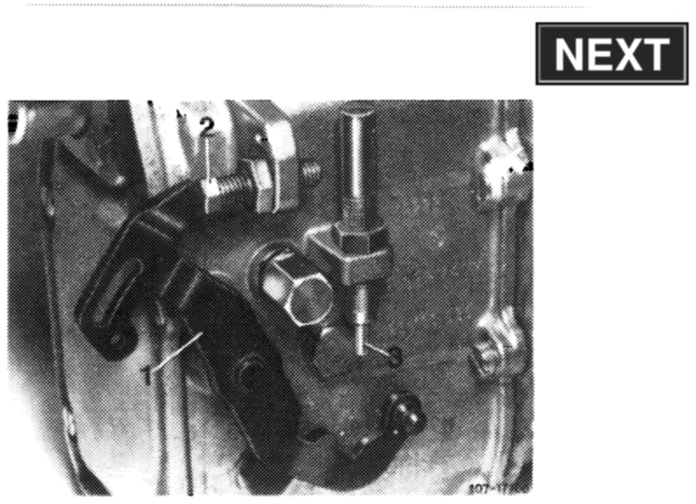
down on accelerator pedal from inside vehicle up to stop. Accelerator pedal and regulating lever (1) should then rest against full throttle stop (2) of injection pump. If required, adjust regulating linkage with adjusting screw (arrow in Fig. item 6) in such a manner that regulating lever (1) rests against full throttle stop (2) of injection pump.
1 Regulating lever 2 Full throttle stop 3 Idle speed stop
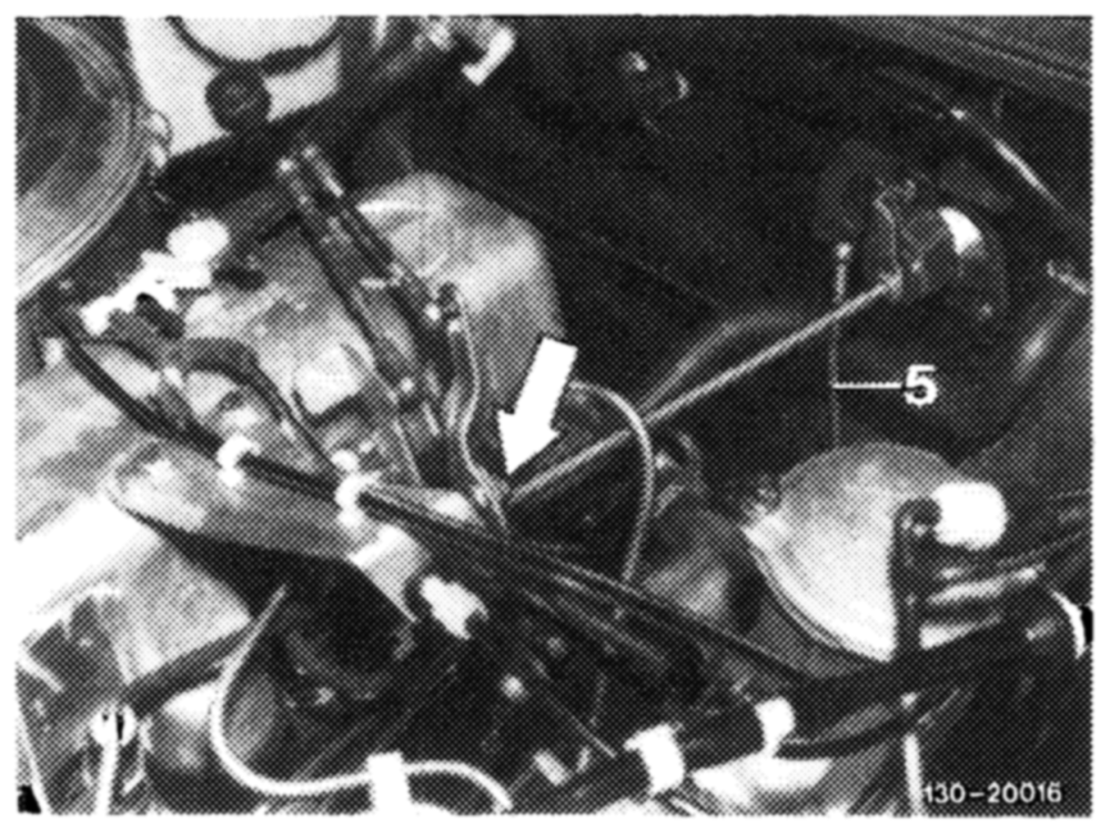
6 If full throttle or idle speed stop (2 or 3) is not attained with this adjustment, adjust push rod (5) from longitudinal regulating shaft to accelerator pedal to 186 mm, measured from center of ball socket to center of damping ring and connect.
Attention!
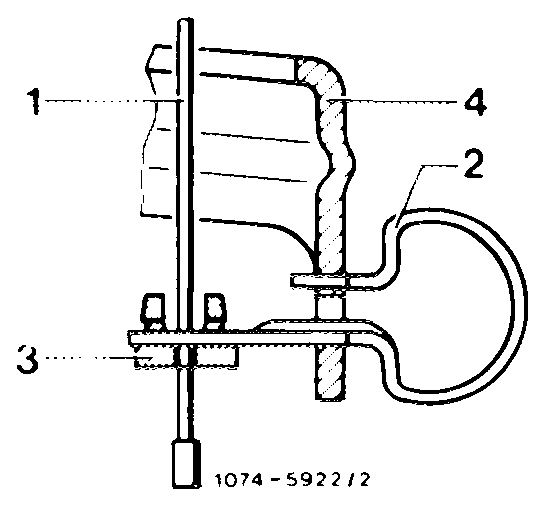
If regulating linkage is not moving to full throttle stop, check whether contour spring for idle speed adjuster is correctly installed.
Cable control for idle speed increase PWN Contour spring Plastic sleeve Guide lever
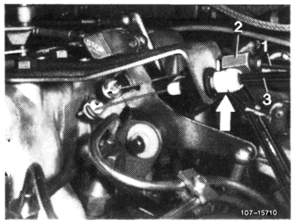
7 Adjust Bowden wire for cruise control/Tempomat. For this purpose, push shutoff lever up to stop. Bowden wire should then rest free of tension against regulating lever.
\f required, adjust Bowden wire with adjusting nut (arrow). Release shutoff lever (idle speed position). This will provide Bowden wire with the required play (arrow).
arrow = Bowden wire for cruise control/Tempomat