Removal and installation of front engine stop
WIS 00-215
Tightening torques Nm (kpm)
| Nut (32) for adjusting screw, type 115.1 | 90 | (9) |
| Bolts (35), type 115.1 Adjusting screw (31 ), type 123.1 | 20 130 | (2) (13) |
| Bolts (35), type 123.1 | 30 | (3) |
Special tools
Torque wrench handle 20–100 Nm (2–10 kpm) : _ 1004-7035, Torque wrench handle 50–200 Nm (5–20 kpm) 001 589 44 21 00 – 001 589 35 21 00
Attachable ratchet, 1/2” drive for Das torque wrench handle , aS 4 – 001 689 42 09 00
Shop-made tool
= 114.5
’ o_ 1 — ‘
; 95\7 161 Gauge to adjust front engine stop i-y> . ~ Z Y (type 123.1) 4 : g Co ry Le! 7 Ta
_ J 11004 = ASM
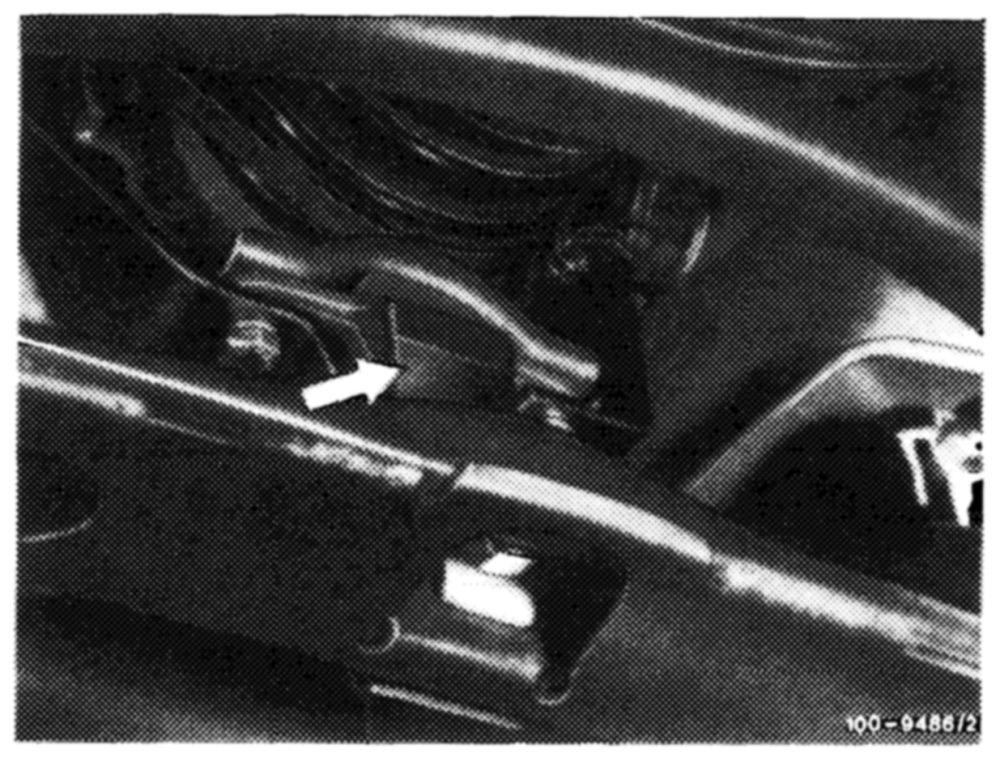
A. Engine 615 in type 115.1
Note On engine model 615 in type 115.1, the engine stop is attached to the end of the engine; on engine models 615, 616, 617 in type 123.1, the stop is positioned beneath the engine between the oil pan and crossmember.
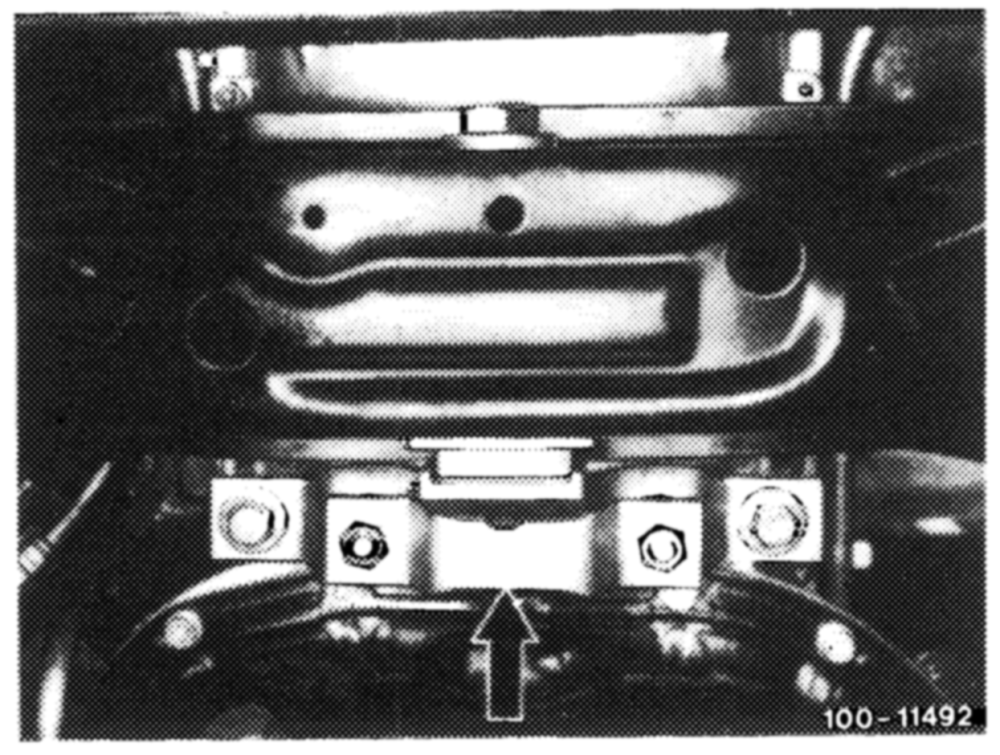
Engine stops with porous or cracked fastening arms (arrows) are to be exchanged.
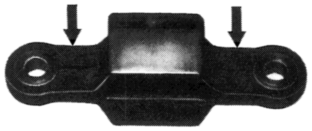
This will also apply if the vulcanized plastic pads are found to be worn out.
Removal
1 Unscrew nut (32) and withdraw adjusting screw (31).
2 Remove plate (39).
3 Unscrew nuts (34) and withdraw bolts (35).
4 Remove engine stop (33) and strap (37).
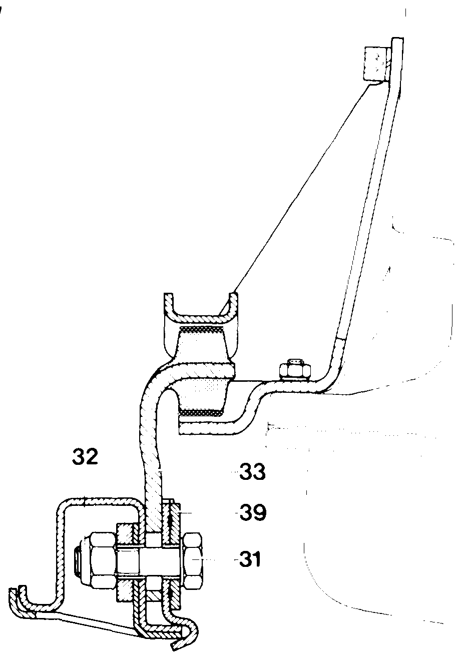
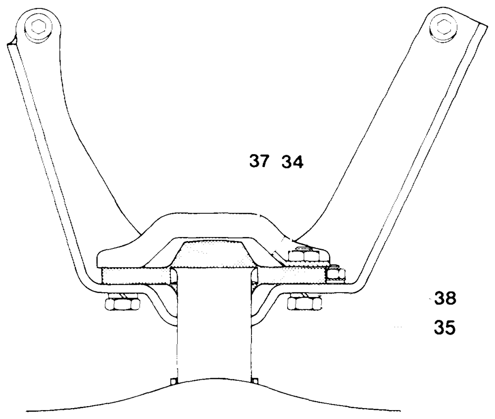
31. Adjusting screw 32) NutM12x 1.5
33 Engine stop
34 NutM8
35 BoltM8x 25
37 Strap
38 Lock washer
39 Plate
5 Insert engine stop (33) and place strap (37) in position.
6 Insert bolts (35) and screw nuts on.
7 Insert plate (39) and adjusting screw (31).
8 Screw nut (32) on but do not tighten.
9 Adjust engine stop (00O—220).
10 Tighten bolts (35) and nut (32) to correct torque setting.
B. Type 123.1
Note
| model 617 with two engine shock absorbers | | = p> |
| not have the engine stop. | ee nnenemmnnnt |
Removal
1 Turn steering to full left or right lock.
2 Lift up retainer (30) at front engine stop and swing away to one side. Remove adjusting screw (31).
3 Unscrew nuts (34).
4 Remove engine stop (33) with strap (37).
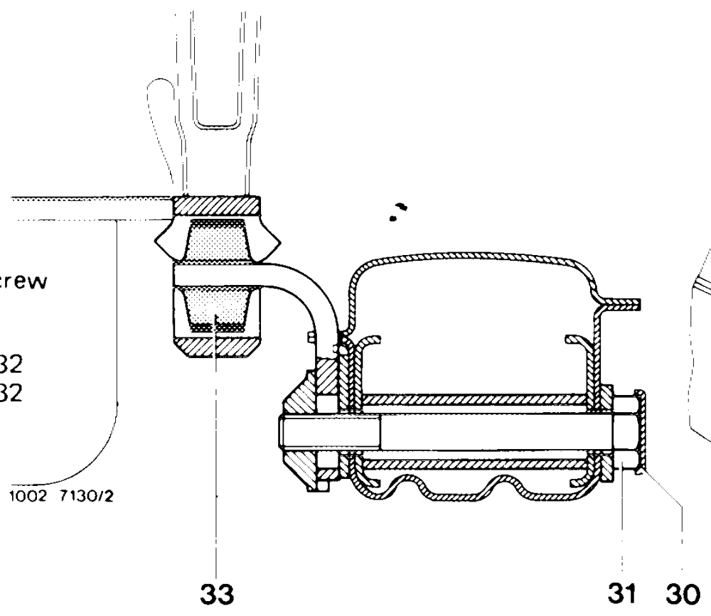
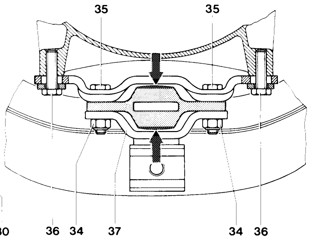
30 Retainer
31 Adjusting
33 Engine stop
34 NutM8
35 Bolt M8 x
36 Bolt M8 x
37 Strap
Installation
5 Place engine stop (33) and strap (37) in position.
6 Insert bolts (35) and apply nuts (34).
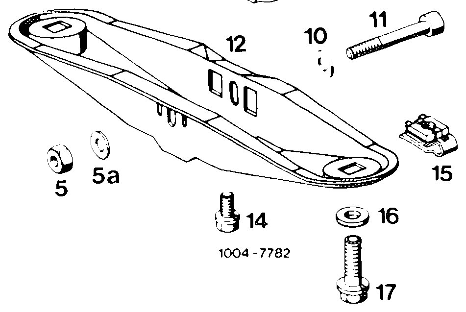
7 If any, release adjusting screw (11) at rear engine mount.
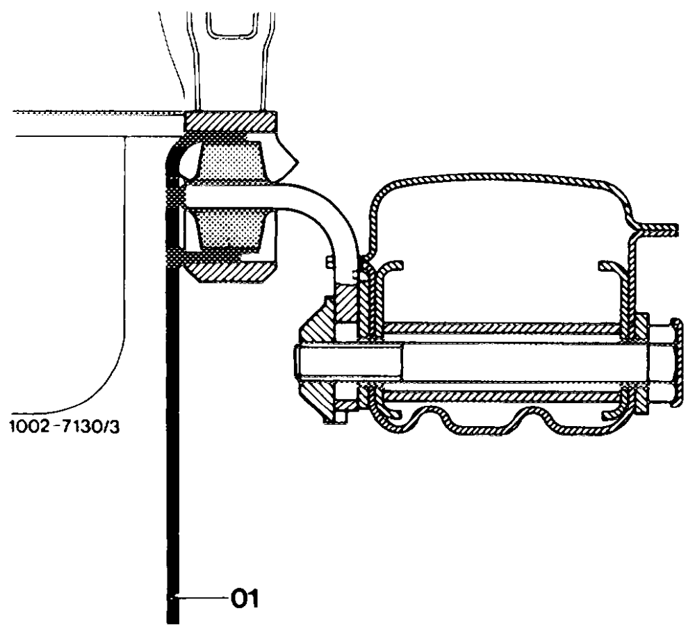
8 Move engine by slightly rocking from side to side with your hands.
9 Position shop-made gauge (01) on front enyine stop.
10 Tighten nuts (34) and adjusting screw (31) to correct torque setting.
11 Withdraw gauge.
12 Secure adjusting screw (31) with retainer (30).
13 Tighten adjusting screw (11) at rear engine mount.
004 ~215/4