Removal and installation of precombustion chambers
WIS 05-117
Data
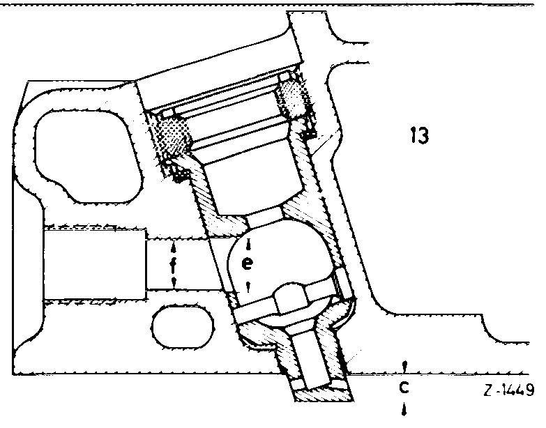
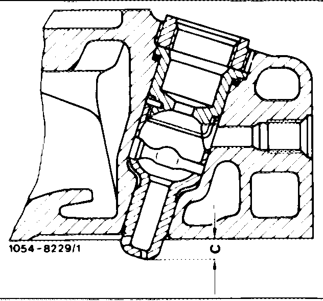
Engine 615.912/941 (44 kW) 615.913/940 (40 kW) Precombustion chamber projection at 616.912/916 (48 kW) cylinder head dimension ‘‘c’’ 5.5–5.9 mm 617.910/912 (59 kW)
Engines 615.940 (44 kw) Precombustion chamber projection 616.912 (53 kW) at cylinder head dimension ‘‘c’’ 7.6–8.3 mm
Tightening torques Nm (kpm)
Cap nuts of injection lines 25 (2.5)
Bolts for cylinder head cover (engine 615) 5 (0.5) Nuts for cylinder head cover (engines 615, 616, 617) 15 (1.5)
Precombustion chamber in cylinder head (screw collar) 150-180 (15–18)
Nozzle holder in precombustion chamber 70–80 (7–8)
Special tools
Box wrench socket open, 17 mm, 1/2” drive S ee ee for injection lines 11004-6359 – 000 589 68 03 00
Socket 27 mm, 1/2” drive eon Ie – 001 589 65 09 00
Pin wrench for screw collar of precombustion chamber a i – 615 589 00 70 00
Extractor for precombustion chamber – 615 589 00 33 00
Box-end wrench 20.8 mm for glow plugs – 617 589 00 03 00
Reamer 3/8” drive for glow plug hole SIE oos esos – 617 589 00 53 00
Note
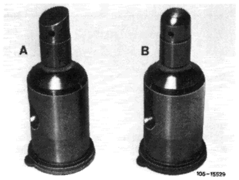
There are two different precombustion chamber versions for these engines.
A 1st version B 2nd version
1st version
Precombustion chambers for normal power engines
The lower part of the precombustion chamber (neck) features 5 holes.
Besides, the precombustion chamber has a slanting neck tip.
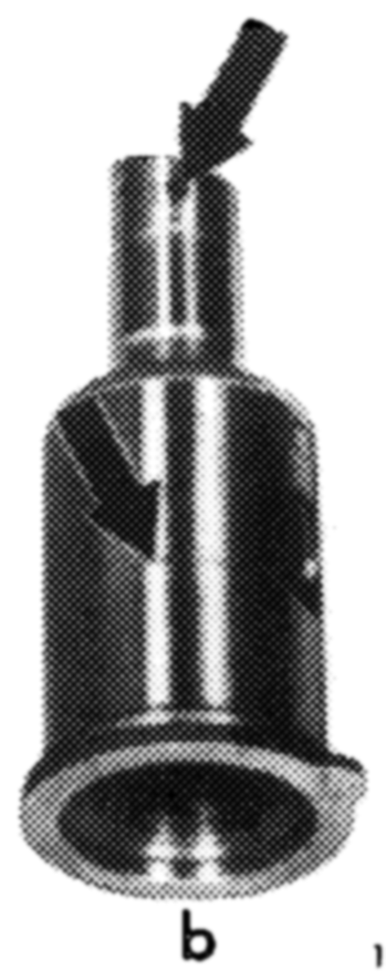
The precombustion chamber for engines 615.913/940 differs from that for engines 615.912/941, 616 and 617 with regard to the burn hole diameter (arrows) and the precombustion chamber volume.
a Precombustion chamber for engines 615.913/940; burn hole dia. 2.6 mm b Precombustion chamber for engines 615.912/941, 616 and 617; burn hole dia. 3.0 mm
Moreover, the precombustion chamber for engines 615.913/940 bears a distinguishing groove (arrow).
Be sure not to use wrong precombustion chamber in wrong engine.
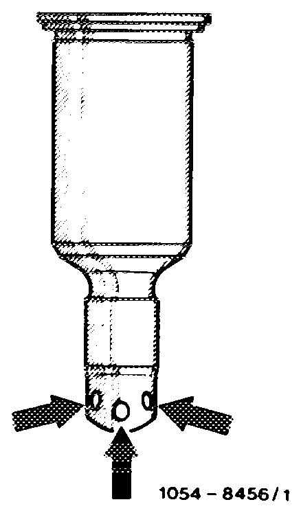
The front 3 burn holes have been bored from 2.6 mm to 3 mm dia. (arrows) to improve the performance of engine 615.940.
Series introduction starting end chassis No. 123.701.
tn future, the Esslingen-Mettingen spare parts division will only supply the type with the 3 enlarged burn holes.
To rectify complaints about poor performance, it is possible to retrofit the modified precombustion chamber in models with lower end chassis Nos.
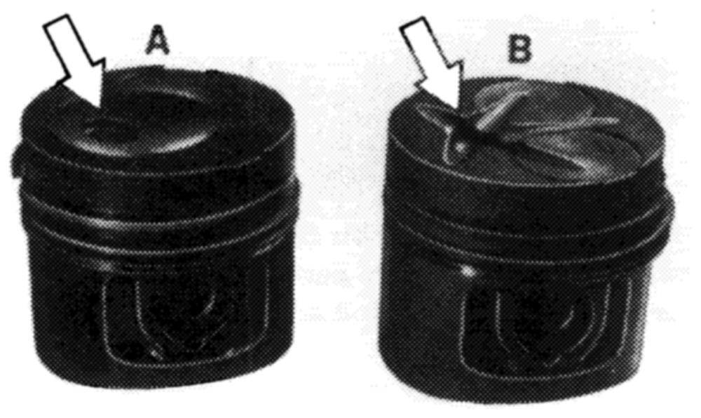
Precombustion chambers with slanting neck tips must not be used in uprated engines, or in connection with pistons having star-shaped combustion chamber cavities (B), because they would strike the piston crown.
103~-15526/1
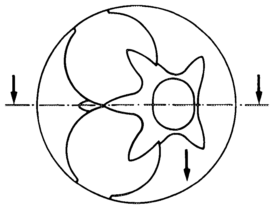
This rule does not apply to normal power engines 615.913/940 which feature pistons with star-shaped combustion chamber cavities and shallow precombustion chamber recesses (C).
C_ Shallow precombustion chamber recess D Deep precombustion chamber recess
2nd version
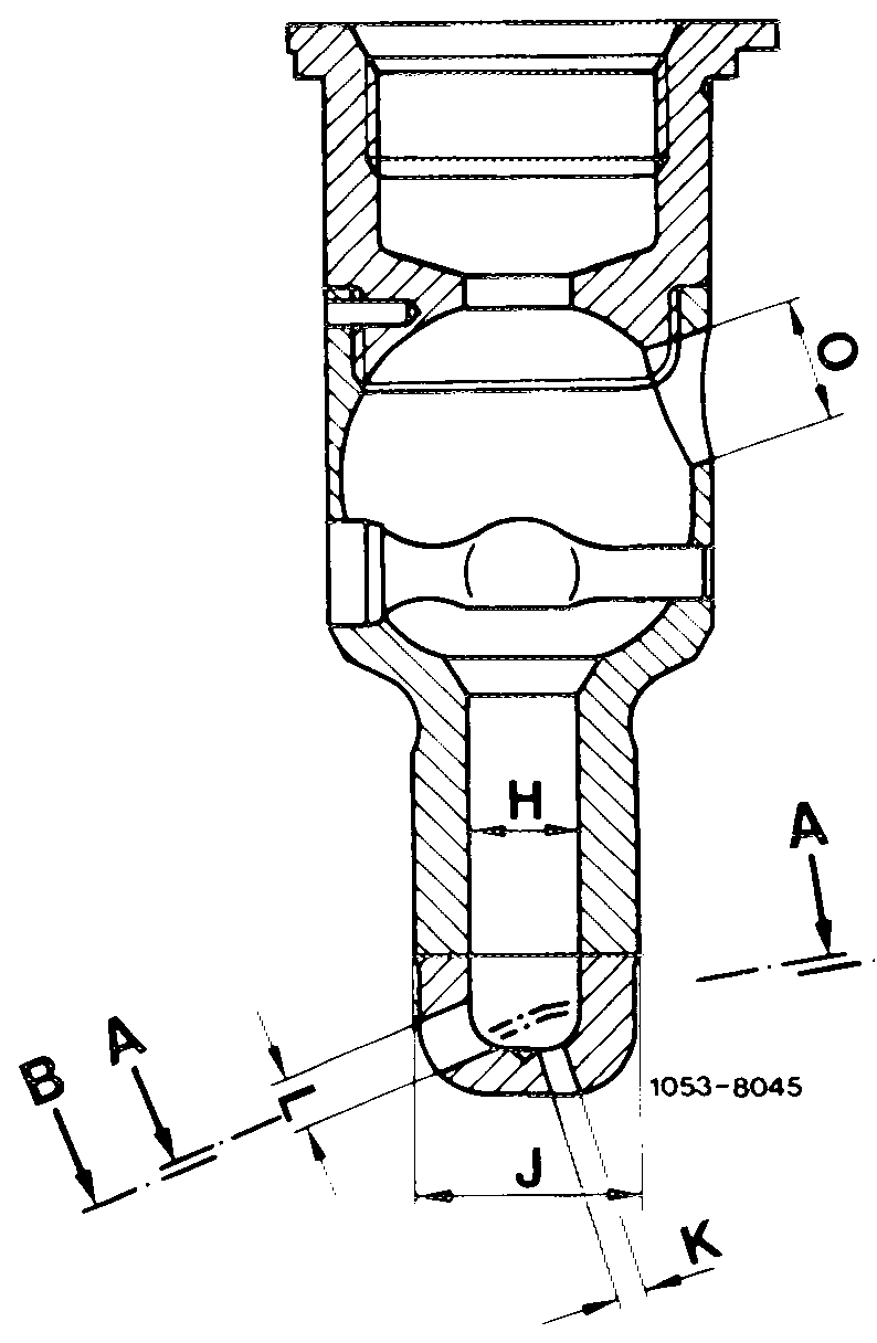
Precombustion chambers for uprated engines
The lower part of the precombustion chamber (neck) features 6 burn holes of different diameters, positioned on different levels and at different angles.
Engines 615.940 616.912 H Precombustion chamber neck bore 6.5 mmdia. 7.0 mm dia. J Precombustion chamber neck OD 14.0 mm dia. 14.0 mm dia. K Burn hole 1.8mmdia. 2.0 mmdia. L. Burn hole 3.0 mmdia. 3.5 mmdia. M Burn hole 2.5mmdia. 2.5mm dia. N Burn hole 3.0 mmdia. 3.2 mm dia. O Glow plug hole 13.5 mmdia. 13.5 mm dia.
Moreover, the end of the precombustion chamber is cup-shaped.
This cup-shape gives uniform wall thicknesses in the area of the burn holes.
The precombustion chamber for engine 615.940 partly has a different burn hole dia. to that for engine 616.912. Besides it is also of smaller volume.
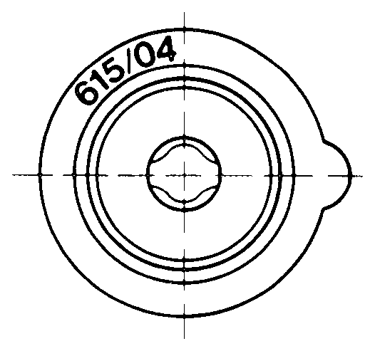
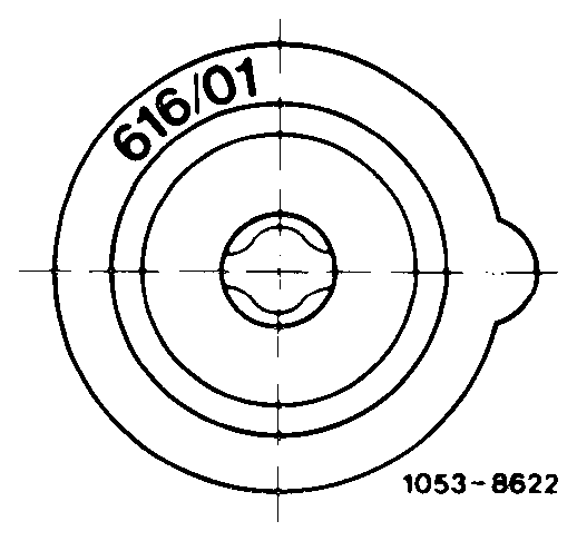
A distinguishing code is stamped in the upper flange of the precombustion chamber (arrow).
A Engine 615.940 ”615/04″ B_ Engine 616.912 ‘616/01
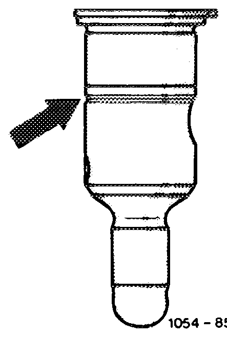
The precombustion chamber for engine 615.940 can additionally be identified by a groove and a cylindrical identation (arrows).
Be sure not to use the wrong precombustion chamber in the wrong engine.
8533
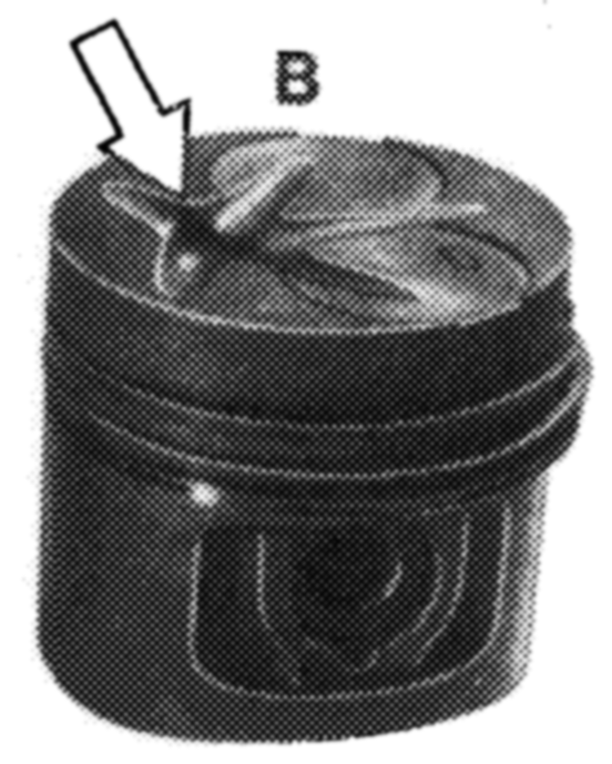
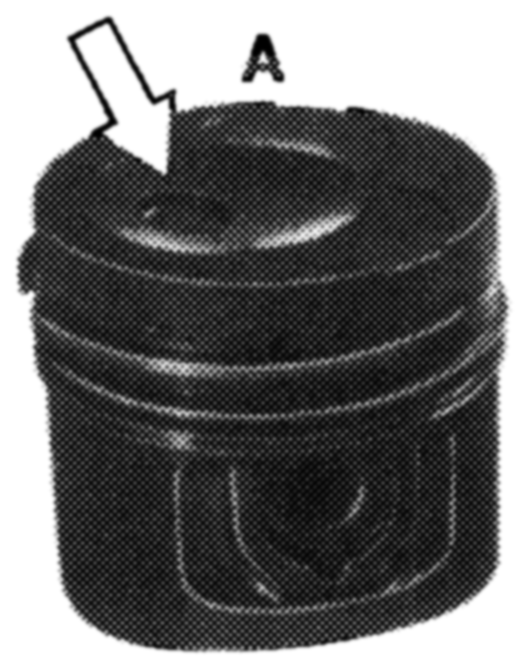
not be used with pistons having round combustion chamber cavities (A) because they would strike the piston crown.
A_ Piston with round combustion chamber cavity B Piston with star-shaped combustion chamber cavity
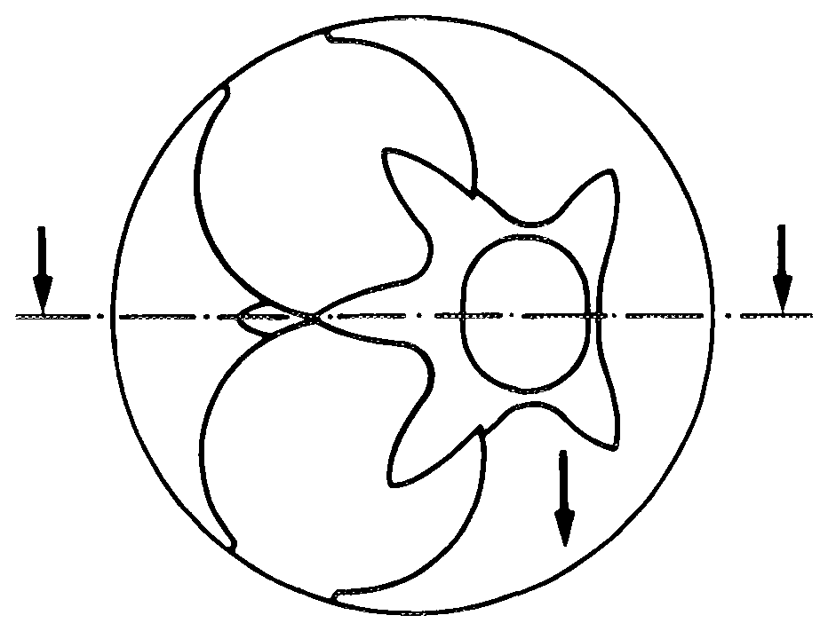
Nor must the precombustion chamber be used in engines 615.913/940 having pistons with star-shaped combustion chamber cavities and shallow precombustion chamber recesses (C) (03-316).
C_ Shallow precombustion chamber recess D Deep precombustion chamber recess
Removal
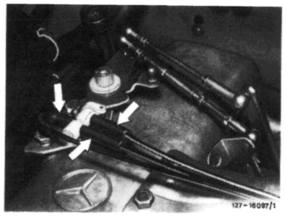
1 Remove cylinder head cover.
On models with automatic transmissions and vacuumcontrolled modulation pressure, additionally disconnect vacuum lines at switch-over valve.
Caution: The vacuum lines must not be crossed. The pipe unions and vacuum lines are color coded.
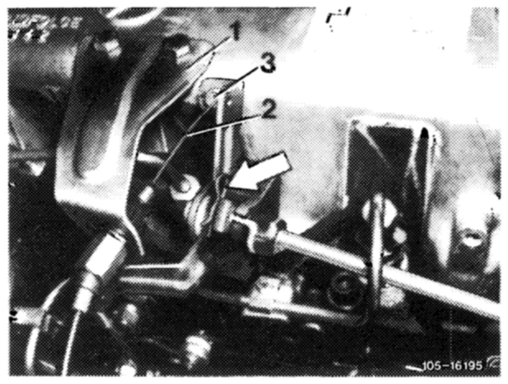
all control rods. Withdraw retainer (arrow) and force longitudinal control spindle in aft direction. Unscrew bracket (1) and unclip idle control cable (2) with plastic sleeve (3).
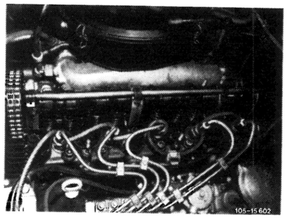
Remove injection lines.
3 Detach fuel return hoses at injection nozzles.
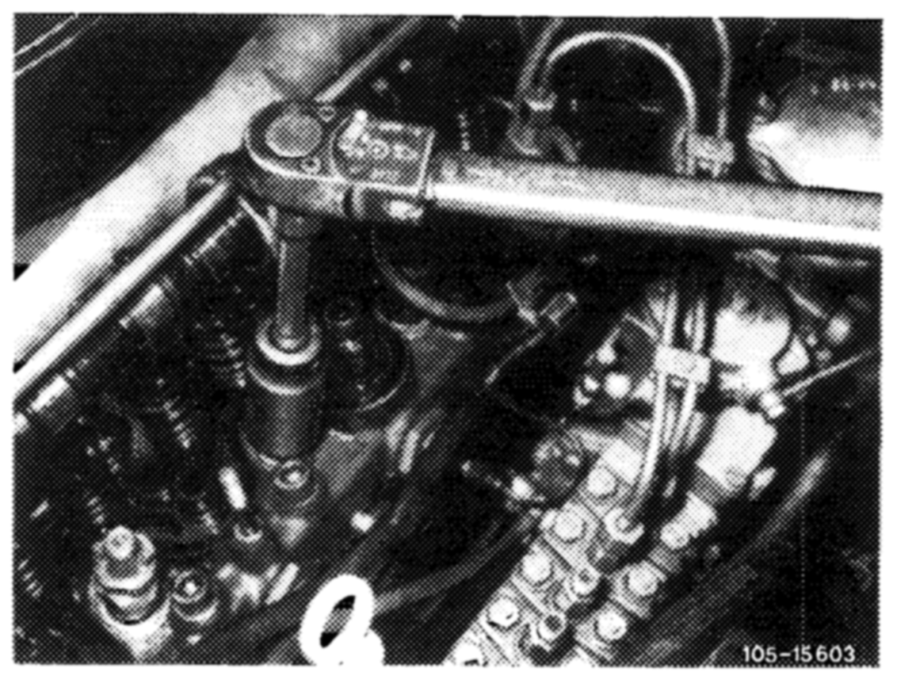
4 Unscrew nozzle holder assembly, using 27 mm socket.
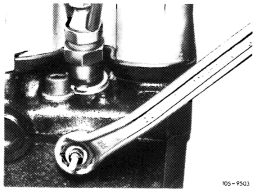
wrench.
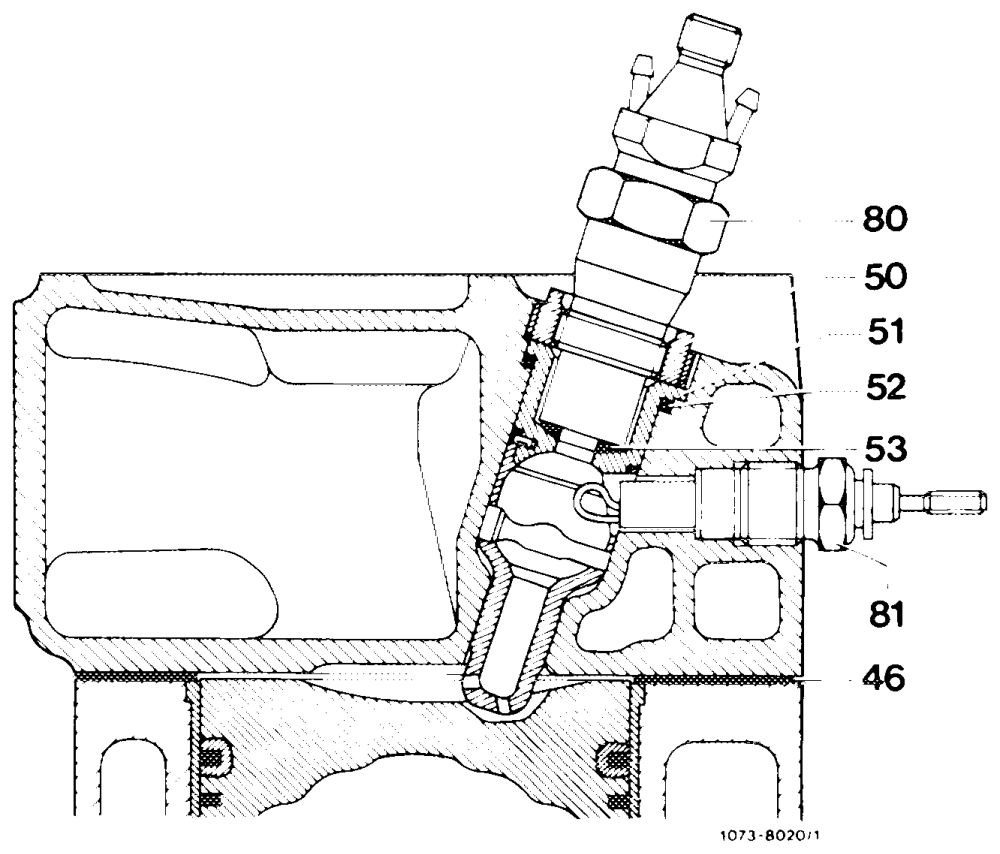
46 Cylinder head gasket 53 Nozzle plate
50 Screw collar 80 Nozzle holder
51 Precombustion chamber 81 Glow plug
52 Sealing ring
6 Remove screw collar (50), using pin wrench.
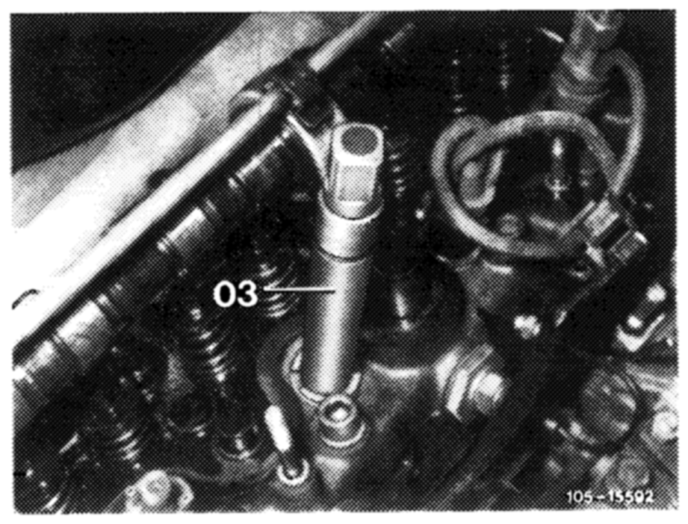
For this purpose introduce threaded insert (03) into screw collar, insert sleeve (02) into screw collar grooves (arrows) and tighten at nut (01).
03 Threaded insert
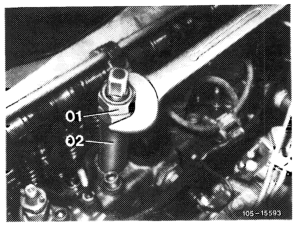
Sleeve (02) must be seated so firmly in grooves that it does not slip out when screw collar is released.
Apply wrench to hexagon part of sleeve (02) and remove screw collar.
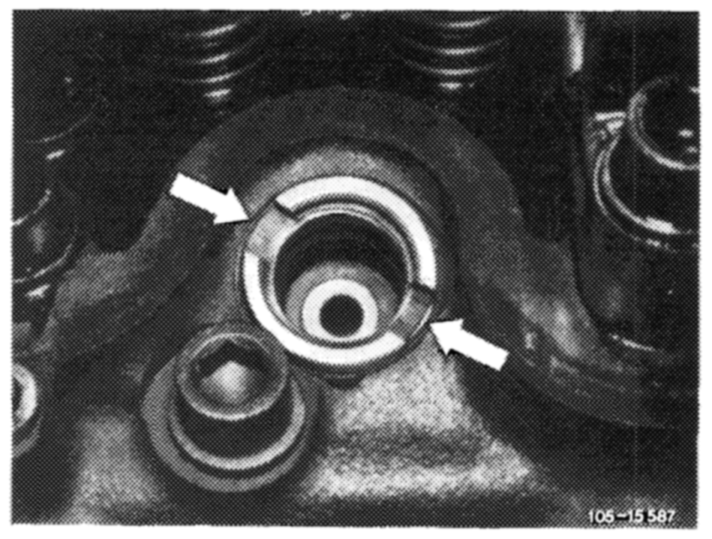
01 Nut 02 Sleeve
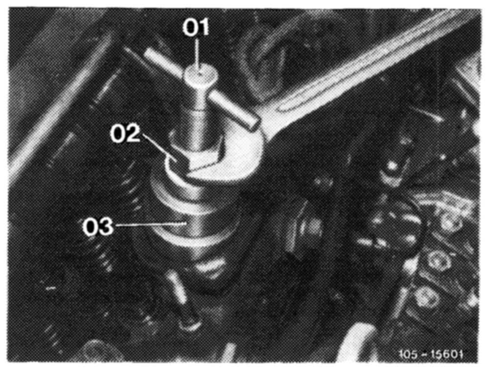
7 Withdraw precombustion chamber using extractor. Screw spindle (01) into precombustion chamber and position remover (03) on cylinder head. The remover has 2 pins, one of which must be located in hexagon socket of cylinder head bolt adjacent to precombustion chamber. Withdraw precombustion chamber, turning nut (02) with open-end wrench.
01 Spindle 02 Nut 03 Remover
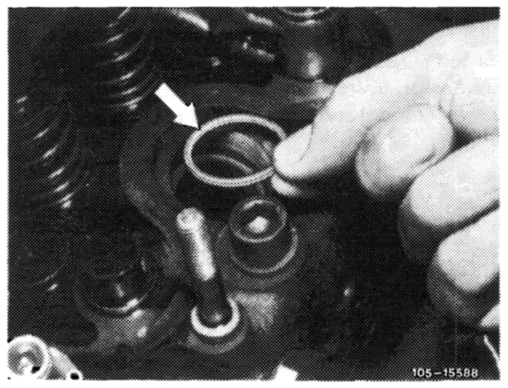
8 Draw sealing ring (arrow) out of cylinder head.
9 Cover bore in cylinder head.
10 Remove carbon deposits from glow plug holes, using reamer (illustration, job No. 14).
Note: If old precombustion chambers are to be put back they must be checked first for satisfactory condition.
The spherical pin must not be burnt or scaly.
Moreover, if burn tips show signs of burning or if lower part of precombustion chamber is cracked, remove intake pipe and examine interior for traces of oil.
|f oily places are found the diaphragm of vacuum pump will have to be checked for cracks and other signs of damage; it may then be considered necessary to replace the vacuum control unit at the injection pump.
Which of the two assemblies has failed can be identified by the vacuum lines (blackened by oil).
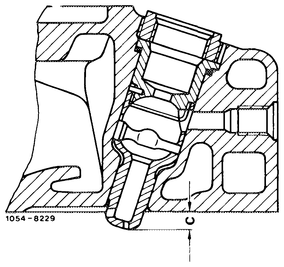
11. Position new sealing ring (52) in cylinder head. Be sure to use nothing but a genuine sealing ring of the prescribed thickness and shape, in order to observe necessary distance (c) of 7.6–8.3 mm between precombustion chamber and cylinder head.
Note: Any cylinder head which has been refaced will require, upon installation of precombustion chambers, thicker sealing rings (52) between cylinder head and precombustion chambers.
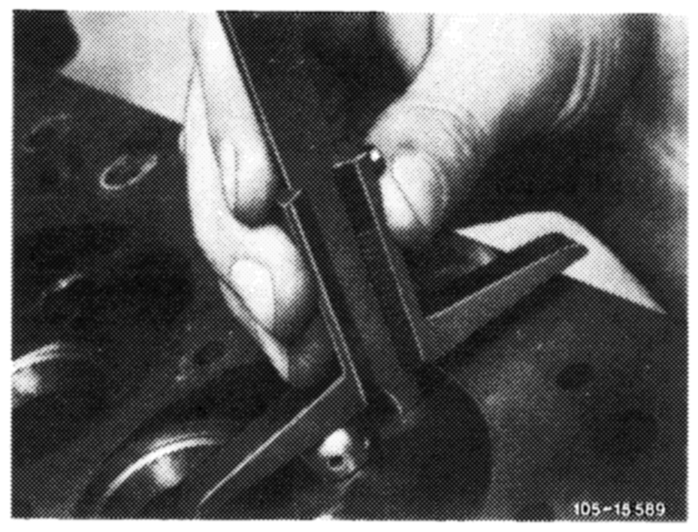
The following sealing rings are available:
Thickness Part No. 1.9–2.1 (standard) 615 017 00 60 2.2–2.4–27 615 017 02 60 – 615 017 01 60 25
2.8–3.0 i 615 017 03 60
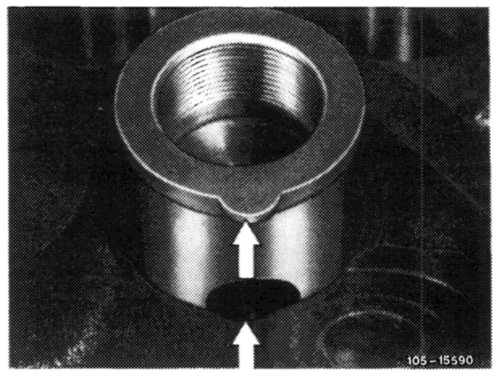
tion chamber (illustration, job No. 7). Apply precombustion chamber so that lug points toward recess in cylinder head (arrows).
Insert precombustion chamber, gently tapping spindle with plastic-headed hammer. While doing so, draw remover (03) upward with one hand and hold securely (illustration, job No. 7).
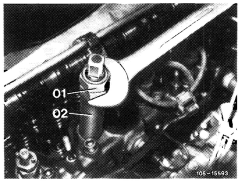
13. Using pin wrench, tighten screw collar (50 in illustration, job No. 5) to correct torque setting 150-180 Nm (15–18 kpm).
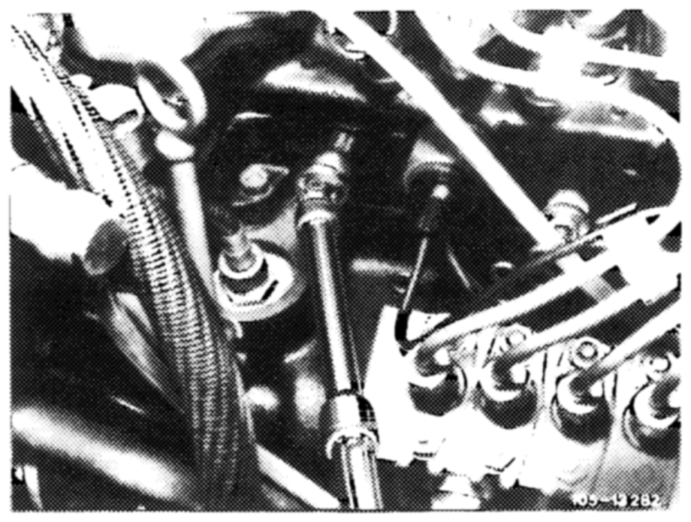
14 If thicker sealing rings have been fitted it will now be necessary to ream off the difference between the through-hole of the precombustion chamber and the glow plug hole. Pack reamer grooves with grease, finally blowing out glow plug hole with compressed air.
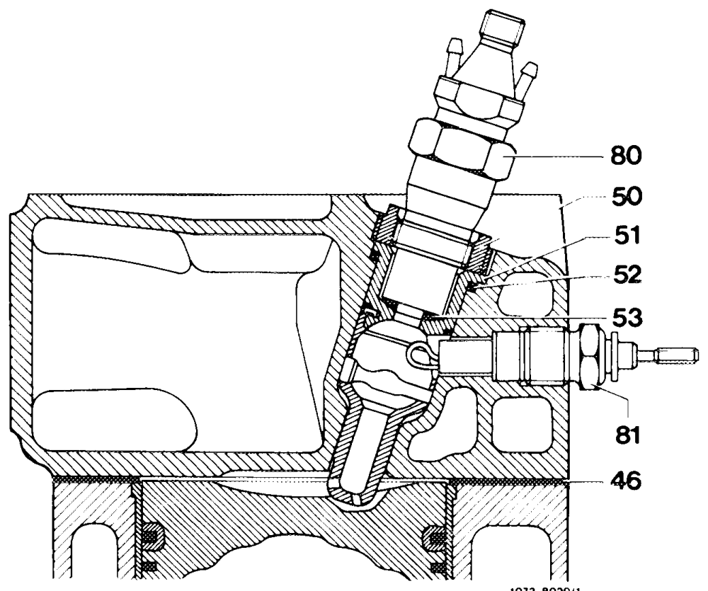
17. Insert nozzle holder assembly (80) and torque to 70–80 Nm (7–8 kpm).
18 Install injection lines.
19 Clip fuel return hoses onto injection nozzles.
20 Fit cylinder head cover.