Checking and replacing valve guides
WIS 05-135
Data
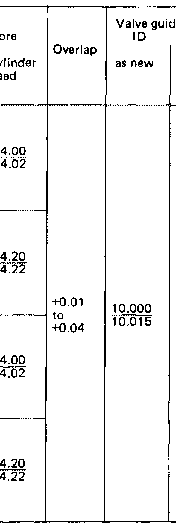
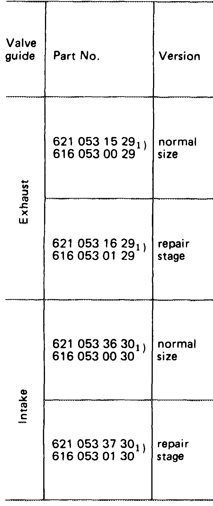
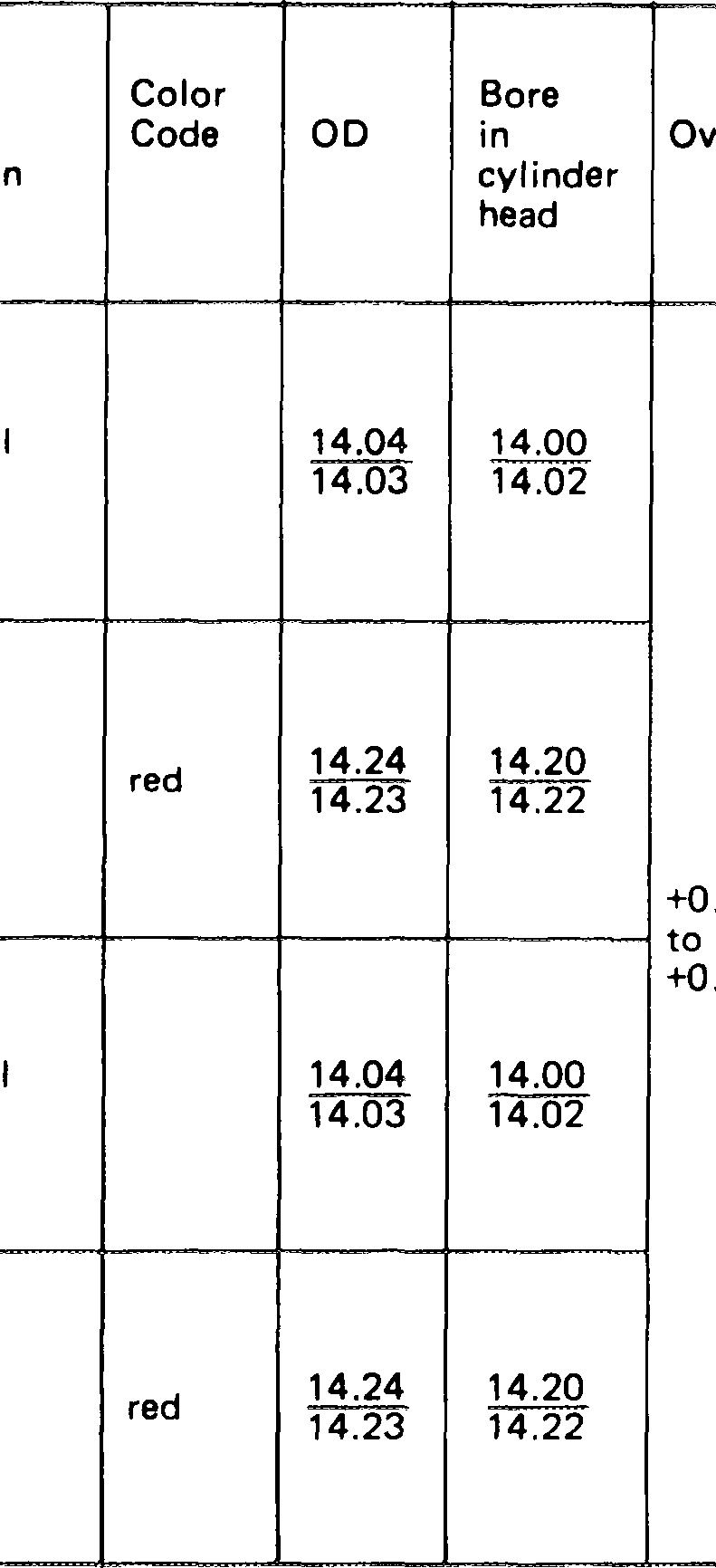

Length tolerance limit
61 1) 60
10.025
49.5 48.5″)
Test pressure 3000–3500 N (300–350 kp) ee _ Co ee These valve guides are 1 mm shorter (see note).
Special tools!)
Plug gauge 10 mm dia. wn – 615 589 00 21 00
Remover 10 mm dia. J ener 615 589 01 1500
Installer 10 mm dia. – 615 589 00 15 00
Special reamer 9.99 H 7 rns) 11004-4197, Hand broach for repair stage 14.2 dia. 115 589 00 53 00 – 000 589 11 53 00
1) Identical for intake and exhaust
Note
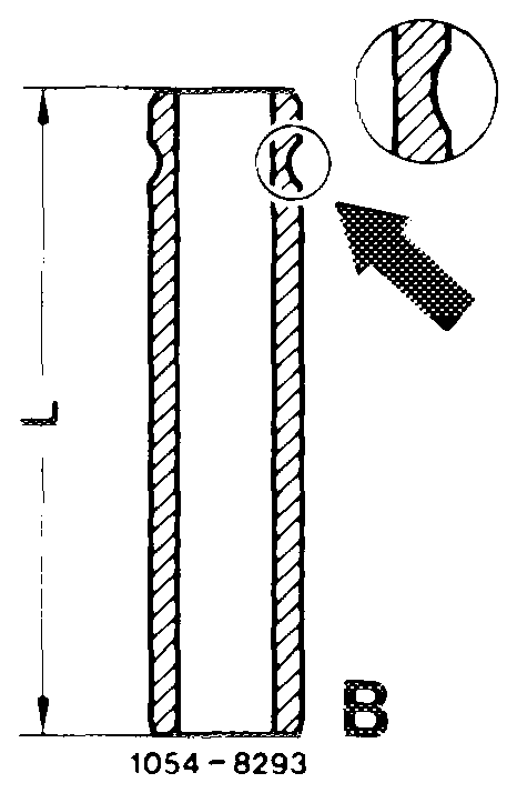
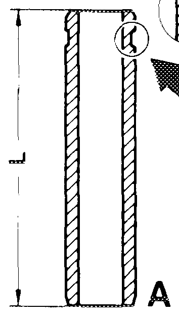
Fes The 61 mm and 49.5 mm long valve guides have been replaced by types of 60 mm and 48.5 mm length, respectively.
They can be distinguished not only by the different lengths but also by the different groove shapes (arrows).
Uprated engines, being of greater valve lift, will only accept the shorter valve guides (B):
Engines 615.940 (44 kW) 616.912 (53 kW)
Checking
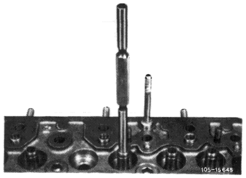
1 Clean valve guide.
2 Measure bore using plug gauge.
Replace valve guide if ‘‘no go” side of gauge slips easily and fully home.
Replacement
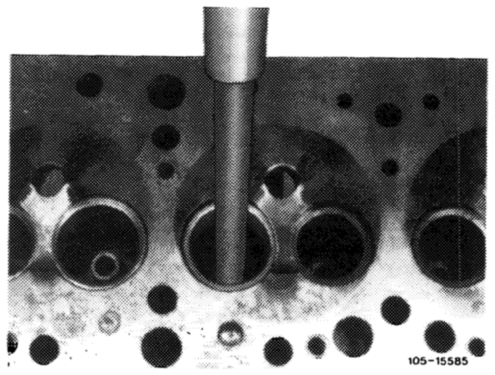
3 Force out valve guide, using remover.
4 Check basic bore in cylinder head for scoring.
Provided specified overlap is still obtained (see job No. 6) normal size valve guides can be used without necessitating any treatment of basic bore.
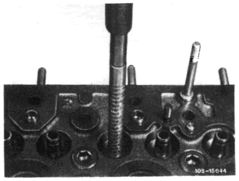
5 If repair stage valve guides are going to be used it is necessary to force appropriate hand broach through basic bore in cylinder head.
This operation can be executed on a drill press. A hand press is unsuitable for this job because the spindle is not accurate enough.
It is essential to position the hand broach perpendicularly over the cylinder head surface.
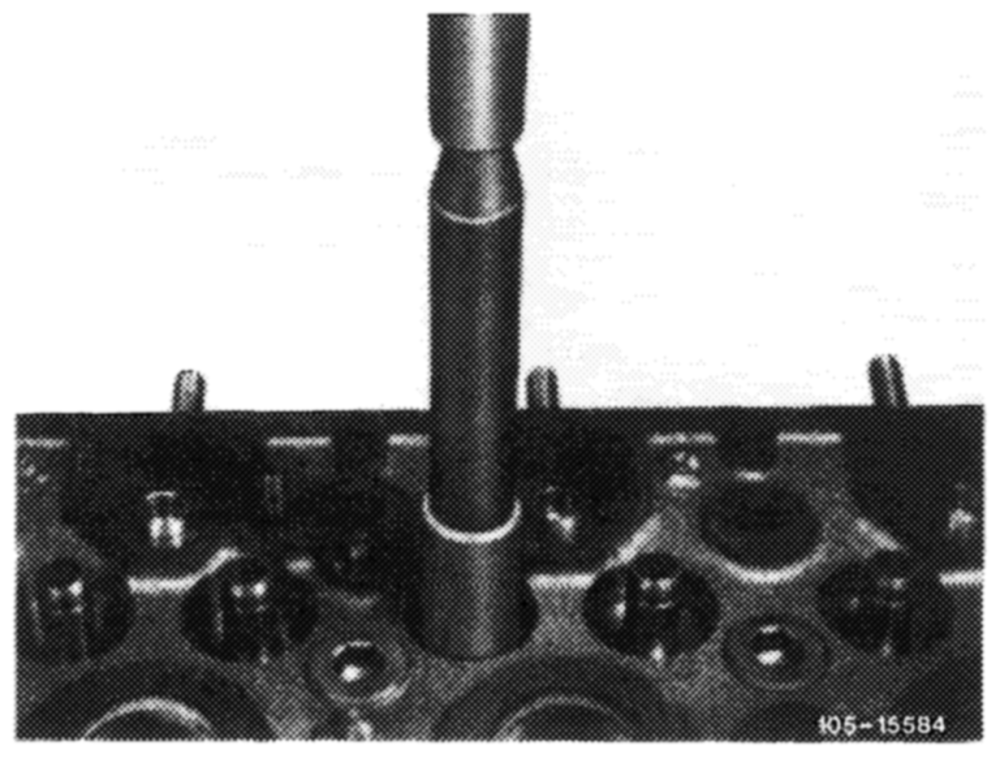
6 Coat valve guides with tallow and, using installer, press home until table dimension is obtained between cylinder head parting surface and underside of valve guide.
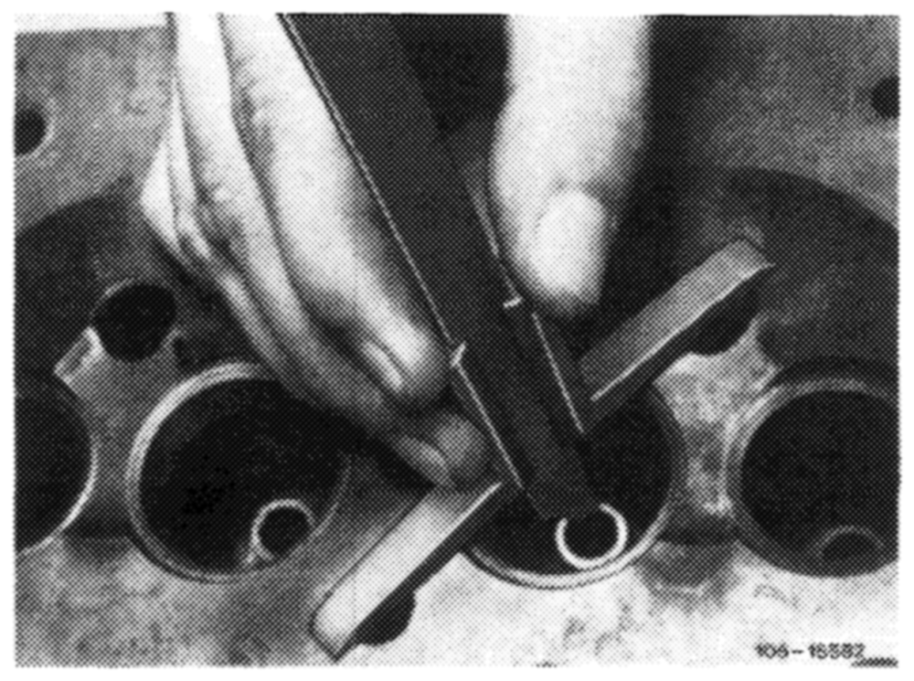
7 Wait until cylinder head has cooled down prior to checking valve guide for firm fit.
Test pressure for firm fit 3500 N (350 kp).
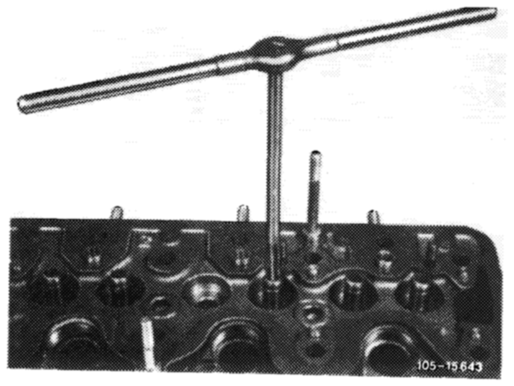
8 Enlarge inside diameter using reamer.
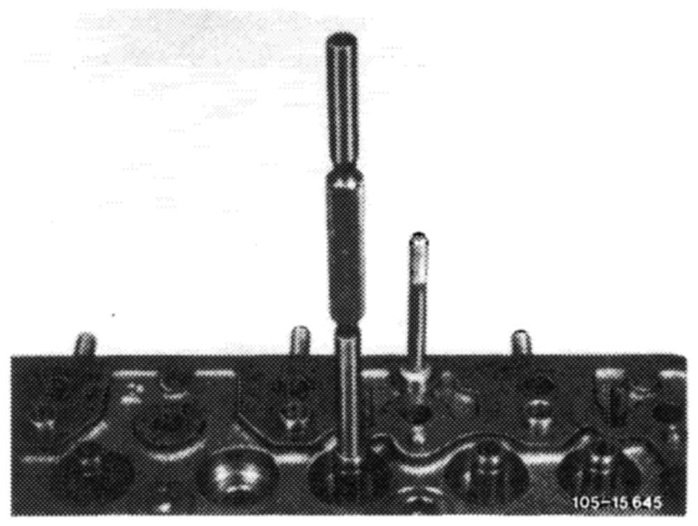
gauge.
The ‘‘go” side ought to drop in.
The ‘‘no go” side must just kiss the surface.
10 Reface valve seats (05—155).