Refinishing precombustion chamber sealing surface
WIS 01-410
Preceding work: Operation no. of the operation texts and work units Nozzle holder removed (01-417). or Standard texts and flatrates 2. 2… ccc eee eee Precombustion chamber removed (01-417).
01
02
-03
PO1-0181–57
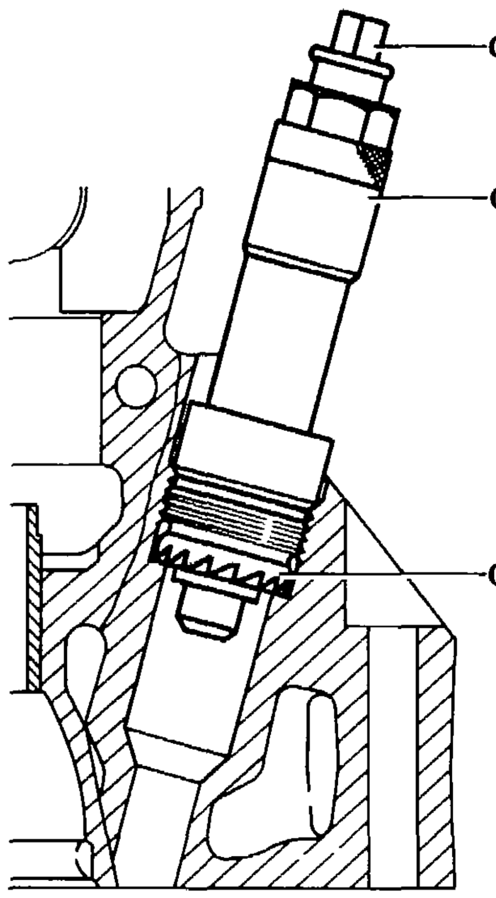
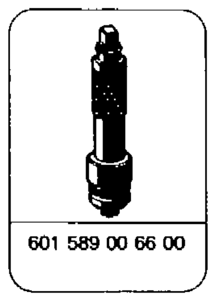
Precombustion chamber mounting bores …… plug or seal off toward combustion chamber (step 2). Countersinking tool 601 589 00 66 00 (01, 02,03) ………….. screw into precombustion chamber mounting bore to be refinished down to stop (steps 3 — 4). Interval „XL ee measure between top of shaft (01) and top of sleeve (02) (step 5).
Note When the cylinder head is installed, measuring interval „X” replaces measuring the projection dimension „C”.
use countersinking tool 601 589 00 66 00 with tap wrench, turn clockwise approx. 5 revolutions while exerting slight pressure (step 6).
AN Do not lift countersinking tool while refinishing. Interval „Xe ee eee measure again (step 7).
Note The difference between the 1st and 2nd measurements corresponds to the material removed and therefore the thickness of the required spacer ring. screw out and clean chips out of mounting bore (step 8). turn over with starter to throw out any chips which may have got into the combustion chamber (step 9). select according to difference in measurements and install (step 10).
Note See table for thicknesses of available spacer rings. Refinished precombustion chamber ………. mark with punch in area of mounting bore (step 11).
Data
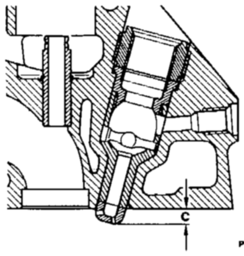
Precombustion chamber projection dimension „C” 7.6 – 8.1 mm
Parts
Designation Part no.
Spacer ring 0.3 mm 601 017 04 60 0.6 mm 601 017 02 60 1.0 mm 601 017 03 60
Refinishing
Note Refinish precombustion chamber sealing surface when damaged or leaking. The first refinishing operation on the precombustion chamber sealing surface can be performed with the cylinder head removed or installed. If the sealing surfaces have already been refinished once before, this can be recognized by the markings (punch marks) in the area of the precombustion chamber mounting POS-0134–13 bores or on the spacers installed. In this case it is necessary to remove the cylinder head to refinish again. The precombustion chamber
projection dimension „C” (7.6 -— 8.1 mm) can
only be measured precisely with the cylinder head removed. Maintenance of this projection dimension assures that the necessary distance between the precombustion chamber and piston crown is present when the piston is in the TDC position.
01.10 – 4140/3
Cylinder head removed:
1 When the cylinder head is removed the scope of work for refinishing is the same except for steps 5 and 7. Instead of steps 5 and 7 measure the projection dimension (c).
Cylinder head installed:
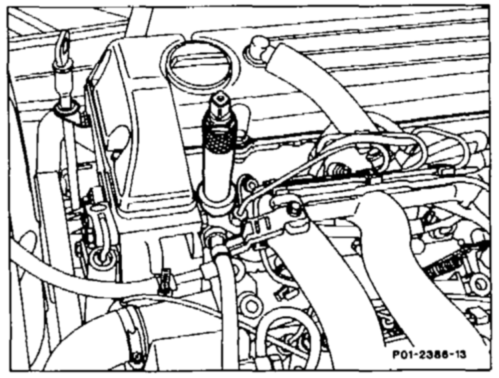
2 Plug or seal off precombustion chamber mounting bores toward combustion chamber (e.g. with rag), so that chips cannot get into the combustion chamber.
3 Screw protective sleeve off of countersinking tool 601 589 00 66 00.
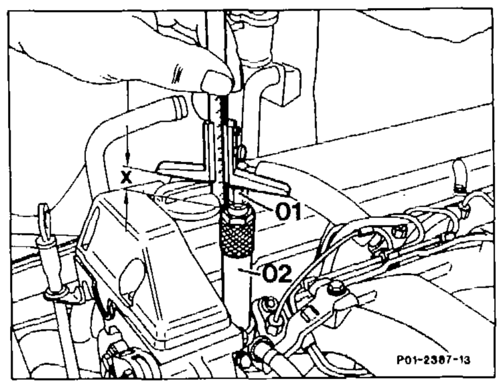
4 Screw countersinking tool 601 589 00 66 00 into the precombustion chamber mounting bore to be refinished down to the stop.
5 Measure interval „X” between top of shaft (01) and top of sleeve (02) and note value.
Note When the cylinder head is installed, measuring the interval “X” replaces measuring the projection dimension „C”.
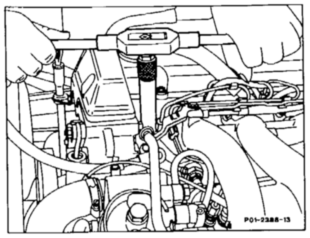
6 Attach tap wrench to countersinking tool 601 589 00 66 00 and turn countersinking tool clockwise approx. 5 rotations while exerting light pressure.
LN Do not lift countersinking tool while refinishing.
7 Measure dimension „X” again. The difference between the first and second measurements corresponds to the material removed.
Determine thickness of spacer ring:
Example:
Calculate material removed Dimension before refinishing = 25.7 mm Dimension after refinishing = 25.5mm
Material removed = 0.2mm
Note In this example the thickness of the spacer ring to be installed is 0.8 mm. Select the spacer ring so that it is at least 0.1 mm thicker and max. 0.3 mm thicker than the amount of material removed.
8 Screw out countersinking tool 601 589 00 66 00 and remove chips.
Note If sealing surface is not completely flat, screw countersinking tool in again and refinish sealing surface again. Then repeat measurement, steps 5 and 7.
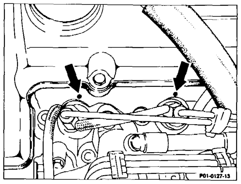
9 Remove rag from precombustion chamber bore and turn over engine with starter to throw out any chips which may have got into the combustion chamber.
10 Insert proper spacer ring.
11 Mark cylinder head with punch mark above each precombustion chamber seat refinished (arrows).
12 Install in opposite order.