Crankcase ventilation — Function
WIS 01-040
A. Standard version
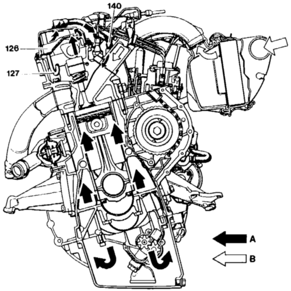
P00-0015–37
Crankcase ventilation, naturally aspirated engine, standard version Engines 601.91, 602, 603.91 126 Oil separator 127 Return pipe 140 Distribution pipe A Blow-by gasses B Fresh air
The crankcase ventilation on standard version naturally aspirated engines is a closed, maintenance-free system.
01.10 – 040/t
The blow-by gases from the crankcase flow through the oil separator (126) into the cylinder head cover and a hose to the distribution pipe (140) on the intake manifold depending on the intake manifold vacuum,
These gases are distributed uniformly to all cylinders by the intake manifold and sucked into the combustion chambers together with the intake air.
The oil deposited in the oil separator runs back to the cylinder head through the return pipe (127).
PO1-0155–57
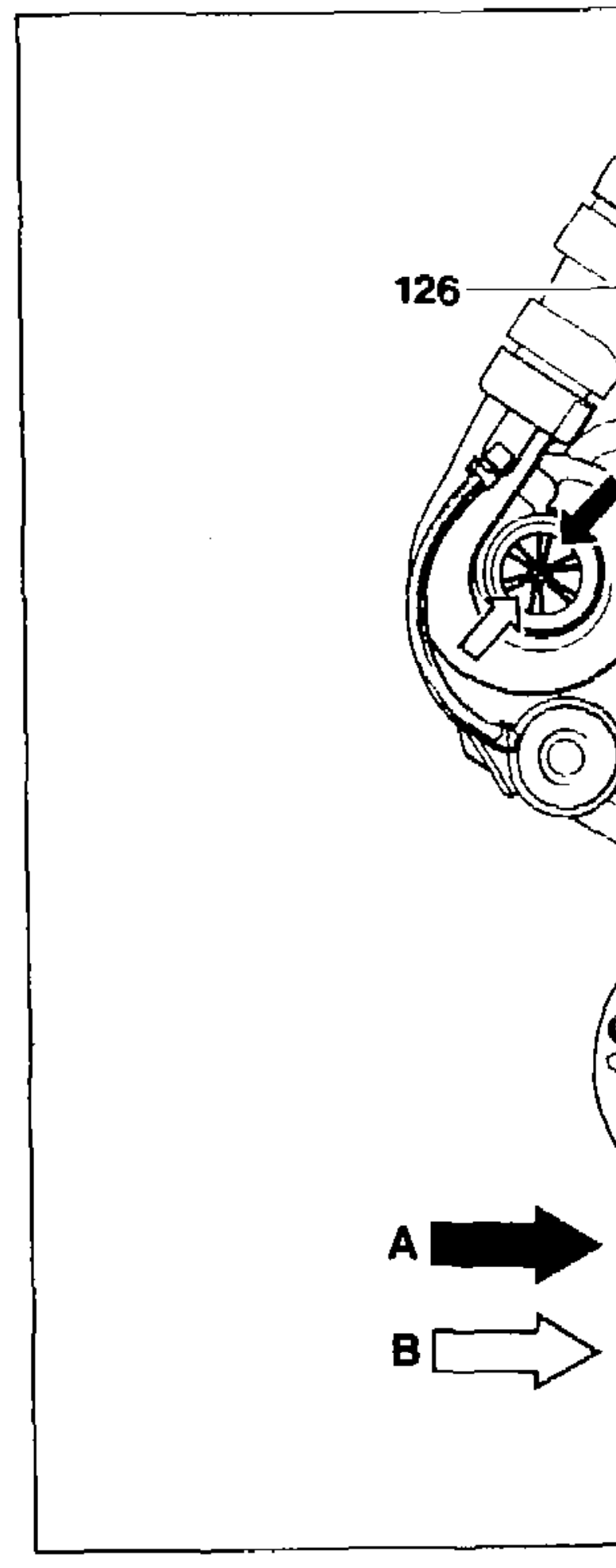
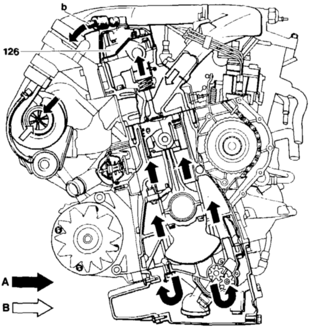
Crankcase ventilation, standard version turbo-engines Engines 602.96, 603.96, 603.97 126 Oil separator b To air cleaner housing A Blow-by gascs B Fresh air
The crankcase ventilation for the standard version turbo-engines corresponds to that of the naturally aspirated engines.
However on the turbo-engines after removal of the engine oil the blow-by gases flow from the cylinder head cover to the intake hose.
B. Naturally aspirated and turbo-engines with exhaust gas recirculation
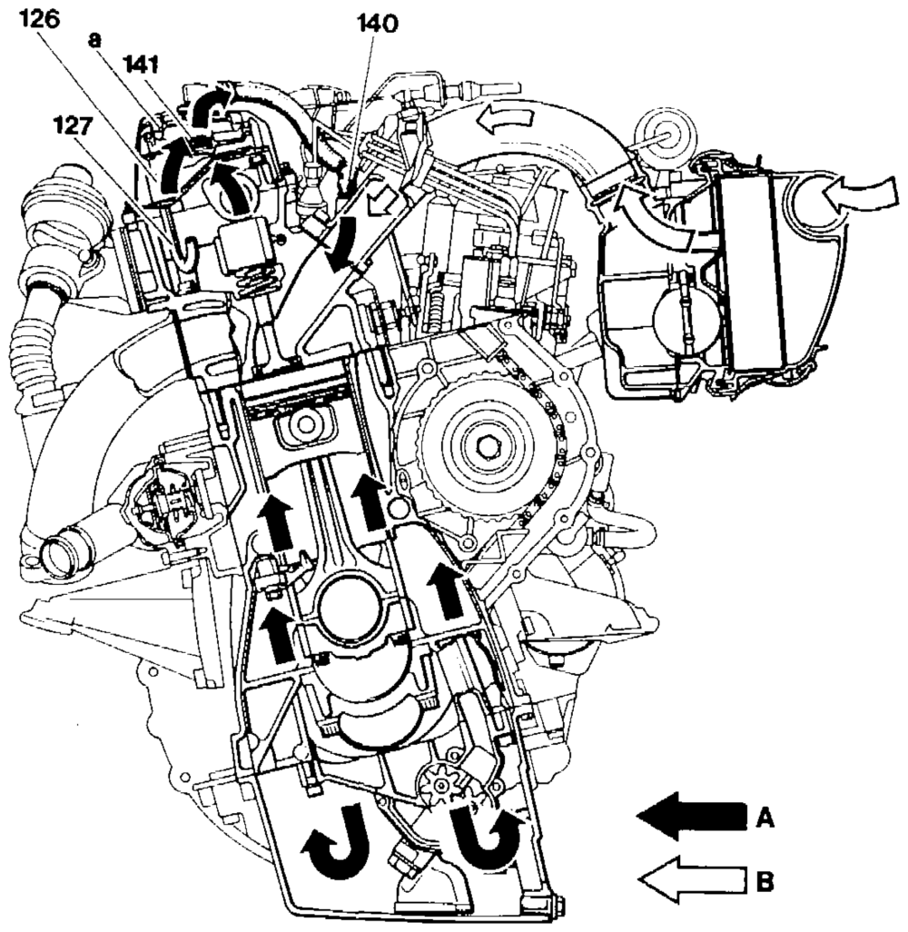
PO1-0156–57
Crankcase ventilation on engines with exhaust gas recirculation Engines 601.91, 602.91, 603.91 Engine 601.913 as of start of production 126 Oil separator 127 Return pipe 140 Distribution pipe 141 Pressure control valve a Vent hole, dia. 3 mm A Blow-by gases B Fresh air
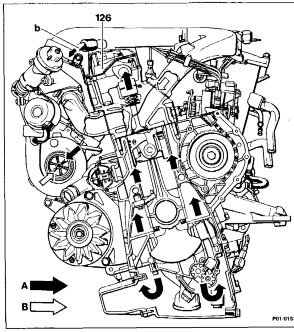
Crankcase ventilation on engines with exhaust gas recirculation Engines 602.96, 603.96/97
126 Oil separator b To air cleaner housing A _ Blow-by gases B_ Fresh air
The crankcase ventilation on naturally aspirated engines with exhaust gas recirculation differs from that of the standard version by addition of a built-in prassure control valve (141).
The pressure control valve is required because on engines with exhaust gas recirculation an additional throttle valve installed in the intake system results in significantly higher vacuums.
If the vacuum were too high, the engine oil would be sucked out of the crankcase.
The pressure control! valve prevents this by keeping the vacuum Constant above a certain value.
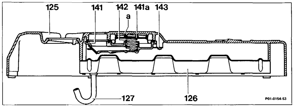
Pressure control valve Engines 601.91, 602.91, 603.91 425 Cylinder head cover 1414 Diaphragm 126 Oil separator 142 Spring 127 Return pipe 143 Holder 141 Pressure control valve a Vent hole
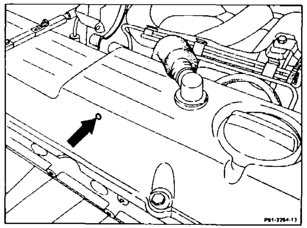
The pressure control valve is designed as a diaphragm-type valve and built into the oil separator in the cylinder head cover,
A hole is present in the cylinder head cover to vent the diaphragm chamber in the pressure control valve (arrow). This hale must not be plugged by dirt or preservation agents.
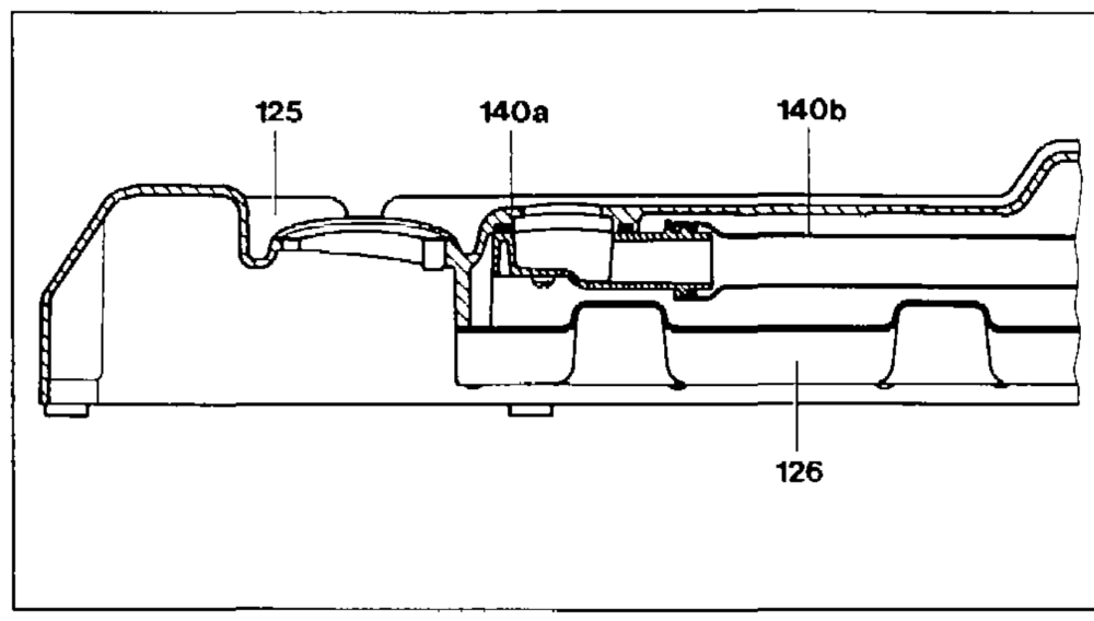
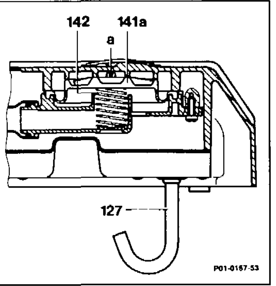
Pressure control valve, engines 602.96, 603.96 125 Cylinder head cover Intermediate section 140b Pressure control valve 126 Oil separator 141a Spring 127 Return pipe 142 Vent hole 140a Angle fitting
Turbo-engines with exhaust gas recirculation are also equipped with a pressure control valve (141a). For space reasons this valve is installed in the rear section of the cylinder head cover.
Note The spring (142) for the pressure contro! valve has been reinforced subsequent to introduction.