ARO1.10-P-2400HX Removing, installing engine 6.10.97
WIS 01-2400hx
ENGINE 601 in MODEL 124, 201, 202
ENGINE 602 in MODEL 124, 201
ENGINE 603 / (except 603.913 /963) in MODEL 124, 126, 140
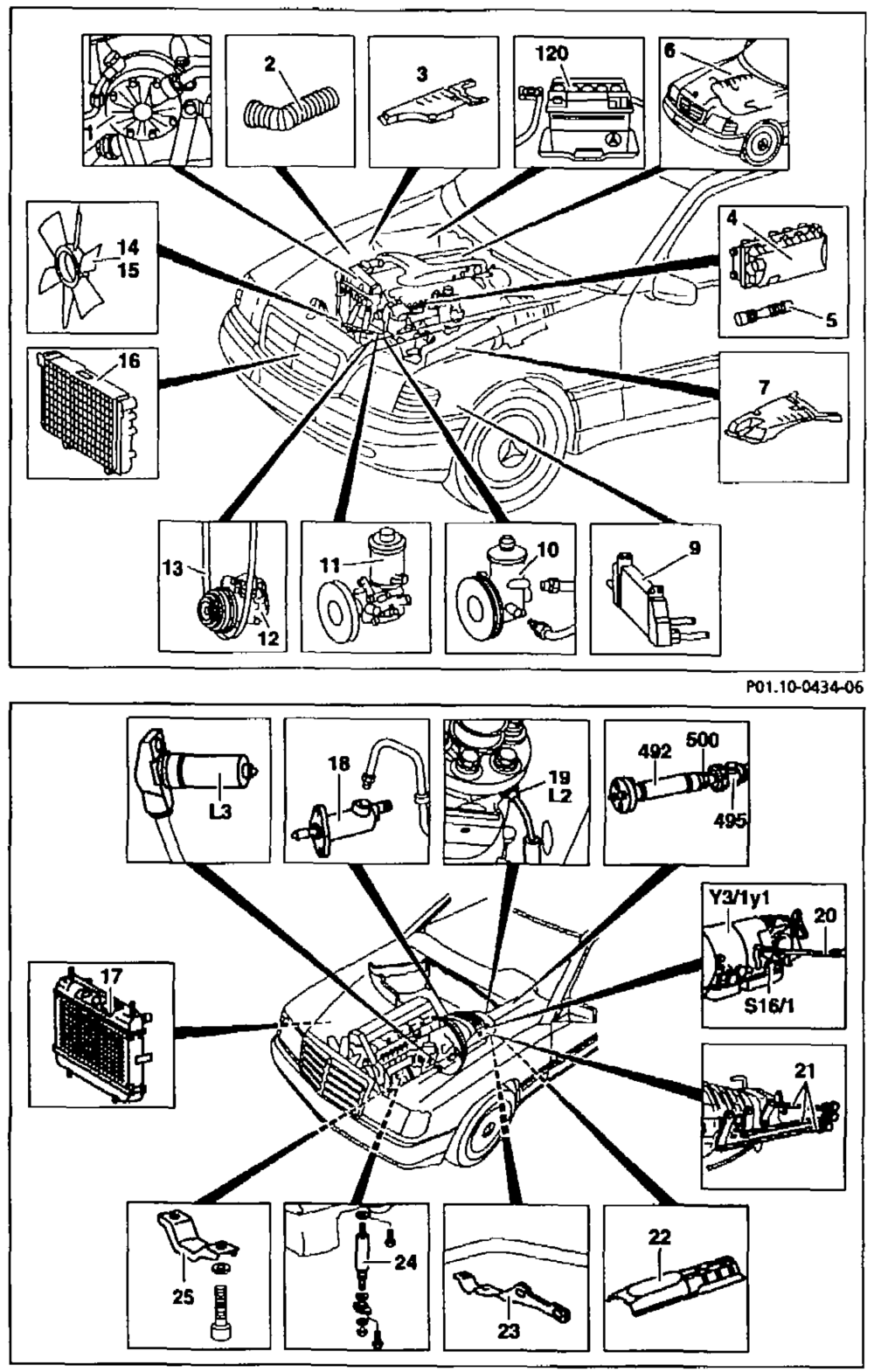
Pressurized oil pump mse CONAN AWN Intake hose Trim panel Air cleaner cover Air intake hose Engine wiring harness Trim panel Air-oil cooler oO ~ Power steering pump Pressurized oil pump/tandem pump AC compressor us NS Poly V-belt 14 Fan 15 Viscous fan 16 Radiator 120 Battery
17 Transmission ait-oi} cooler Clutch sensor 18 19 Speedometer shaft 20 Shift rod 21 Shift linkage 22 Heat shields Exhaust side support 23 24 Engine shock absorber 25 Engine stop bracket 492 Propeller shaft 495 Propeller shaft intermediate bearing 500 Clamping nut
12 Speedometer inductive sensor L3 Speed sensor S16/1 Starter lockout switch Y31/ly1 Automatic transmission
PO1.10-0435–06
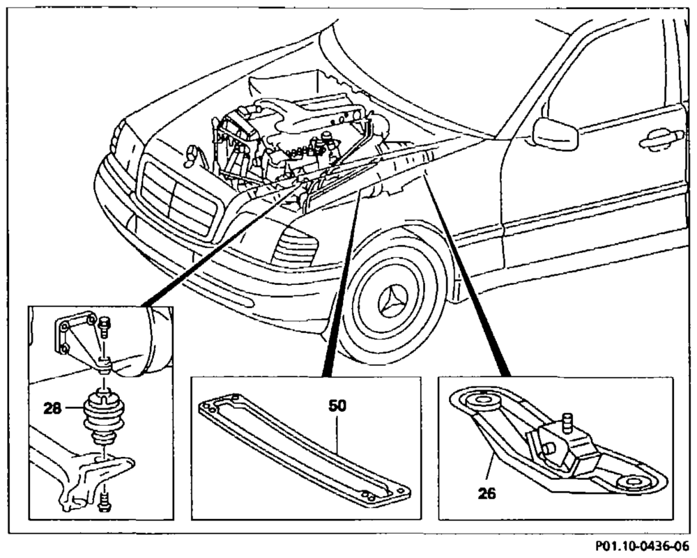

SO Transverse yoke
Removing, installing
Remove bottom engine compartment panel
Remove exhaust system
Disconnect negative and positive cables of battery (120)
Detach air intake hose (5) aspirated engine
Air cleaner cover (4) aspirated engine
Take off trim panels (3 and 7) 140
engine Detach intake hose (2) to turbocharger Unbolt ATF lines and seal with camps automatic transmission fitted – 000 589 40 37 00
Detach transverse bridge and strut 202
Detach hood cable 202
Remove radiator (16) AR20.20-P-3865HW
AR20.20-P-3865HA Fit on guard plate after removing radiator.
Slacken coolant hoses between engine and chassis and detach
Take off fan (14) 601 in model 124, 201 with 20-330 fan clutch
Remove viscous fan clutch (15) models 140, 202 AR20.40-P-5660HW
Remove poly V-belt (13) fitted AR13.22-P-1202HW
Take off AC compressor (12) fitted, do not disconnect the lines at the compressor. Attach to side in engine compartment.
Slacken vacuum hoses and fuel fines between engine and chassis
| Detach Bowden cable of throttle control | 202, 202 except engine 602.96, 201 with engine 602.96, 603.96 | ||||
| 19.1 | Detach throttle control linkage | Model 126 30-1010.c | |||
| 20 | Separate electric connecting cables between engine and chassis, plug connections and connectors | BS | | |||
| 21 | Separate plug connection of oil pressure switch and oil level sensor | ee | |||
| 22 | Detach connection cables of starter | ||||
| 23 | Separate plug connections of generator | ||||
| 24 | Take off engine wiring harness (6) | Bn | |||
| 25 | Extract power steering pump (10) hydraulic oil from reservoir and disconnect oil lines | Fill power steering pump | |||
| Disconnect pressurized oil purnp (1) or tandem pump (11) oil lines and hoses between engine and chassis | with level control and /or ASD | ||||
| 27.1 | Unbolt air-oil cooler (9) oil fines and hoses between cooler and engine | engine or naturally aspirated exhaust gas recirculation | |||
| 28.1 | Disconnect transmission air-oil cooler (17) oil lines and hoses between cooler and engine | engine with automatic and tratler hitch in with AC | |||
| 29.1 | Detach engine stop bracket (25) | Model 201: Inspect engine | |||
| 30.1 | Detach left engine shock absorber (24) | 201 (up to 03/85) | |||
| 31.1 | Detach left and right engine shock absorbers (24) | 126 | |||
| 32 | Detach shift linkage (20) | ||||
| 33.1 | Unbolt clutch sensor (18) hydraulic line | transmission | Bleed clutch sensor | ||
| Unplug starter lockout, reversing light switch cable connection | automatic transmission fitted | ||||
| 35.1 | Unplug kickdown solenoid valve cable connection | automatic transmission fitted | |||
| 36 | Unbolt speedometer shaft (19) and speedometer Inductive sensor (L2), respectively | a | |||
| 37 | Unbolt speed sensor (L3) and ground strap of starter | ||||
| 38 | Unbolt exhaust side support (23) | ||||
| 39.1 | Unbolt heat shield (22) at center tunnel | automatic transmission fitted | |||
| 40 | Unbolt propellor shaft (492) | Removing and installing propellor | 126 | ||


Detach propellor shaft intermediate Removing and installing propellor 41 bearing (495) 126
Slacken clamping nut (500) at intermediate torques see Removing and 42 propellor shaft, model 124, 126 bearing
| 43 | Unbolt transverse yoke center section (50) | 126: Replace self-locking bolts | |
| Attach engine to engine hoist and position horizontally | (self-locking) | ||
| 45 | Attach guard plate to component compartment panel | q | |
| 46 | Unbott rear engine supporting bracket (26) | adjusting bolt of rubber mounts | |
| a7 | Unscrew hexagon socket bolts of front left and right engine mounts (28) from below | in mode 201 up to 03/85 in model 201 up to 03/85 in model 126 in model 124, 201 as of 04/85 in model 124, 201 as of 04/85 in model 124, 140 in mode! 202 | |
| 48 | Lift engine out of engine compartment with engine hoist | Inspect engine ail, top up or refill engine. coolant. cooling system for leaks. | |
| 49 | Install in the reverse order | Bn | |
| aA Danger! 50 | Risk of accident as a result of vehicle starting off when engine running. Risk of injury as a result of bruises and burns if you insert your hands into engine when it is being started or when it is running. Run engine and inspect for leaks | vehicle to prevent it starting off. and close-fitting work clothes. hot or rotating parts. | |
| 51 | Read fault memory, erase. | ADO0.00-P-1000AZ | |
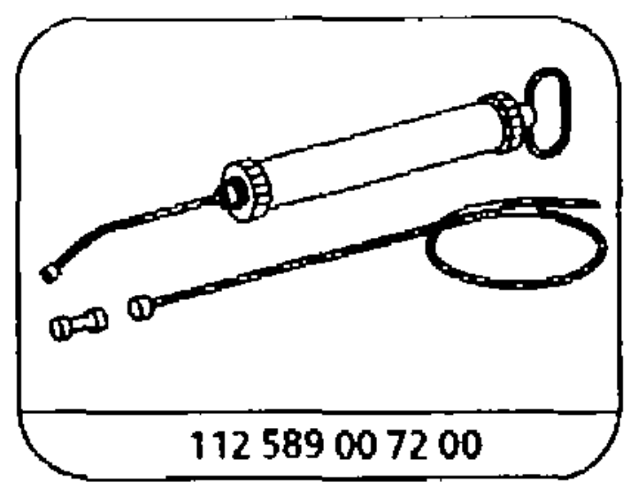
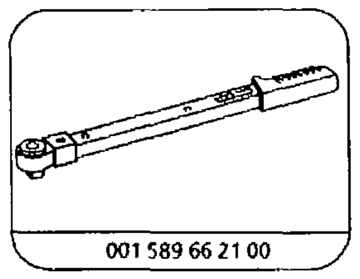
a aan 7 we By as 00089403700 \_ 126589000100 = \_ 201589000100 Clamp Hand pump Open-end wrench Open-end wrench
Torque wrench
Commercially available tools (see Workshop Equipment Manual)
Number Designation Make (e.g.) Order number
WHS58.30–7-1001-07A Engine hoist (self-locking) Backer 3188 HerderstraBe D-42853 Remscheid
WHS8.30-Z-1002-07A Shackle C1 DIN 82101
| AS00.00-Z-0005-01A | Risk of accident as a result of vehicle | Secure vehicle to prevent it from | A Danger! |
| starting off when engine is running. Risk of moving off. | |||
| injury as a result of bruises and burns if you Wear closed and close-fitting work | |||
| insert your hands into engine when itis | clothes, | ||
| being started or when it is running. | Do not grasp hot or rotating parts. | ||
Rules of conduct / Protective measures Possible dangers – Asageneral rule, carry out work on the running engine only if Risk of accident this is absolutely essential. from vehicle starting off during starting operation (e.g. when – Before starting the engine, apply parking brake. testing compression pressure) as a result of gear engaged or when – On models with manual transmission, move gearshift lever engine running and vehicles with automatic transmission as a into Neutral position.
result of selector lever position “P” or “N™ not engaged
– Onmodels with automatic transmission, move selector lever (exception: some vehicles do not have a selector lever position into position „P” or „N” (exception: some vehicles do not have a selector lever position “P”). “P*). On models which do not have selector lever position “P”, secure selector lever to prevent It from being operated Risk of injury unintentionally. Severe injuries may be caused by freely rotating parts in the area – Wear closed and close-fitting work clothes. of the running engine. The heat produced by the engine when it – Take off any jewetry, such as chains, rings etc. is operating can result in severe burns if contact is made with – Ifyou have long hair, wear a suitable head cover. individual, unshielded parts. – Before commencing work on the running engine, check to obtain a general picture of the positioning of parts which may be hot. – When carrying out work when starting the engine or when engine is running, do not touch any hot and rotating parts.
First ald measures In the event of burns @ Donotrub the skin areas affected; flush with plenty of cold water and cover skin with sterile bandages. e Immediately consult a physician.