Testing coolant level indicator
WIS 20-440
Model 124
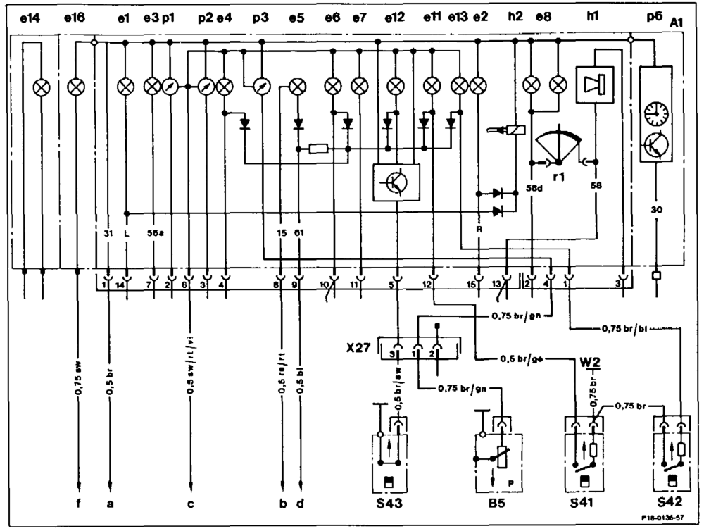
Wiring diagram of engine oil level indicator, coolant level indicator, windscreen washer level indicator (see Wiring Diagrams Volume 3 and Volume 4 for further information) Al Instrument cluster Oil pressure sensor BS Coolant level indicator lamp switch e1 Left turnsignal indicator $41 Windscreen washer level indicator lamp switch e2 Right turnsignal indicator $42 e3 High beam indicator S43, Oil level indicator lamp switch e4 Fuel reserve warning tamp Ground, front right next to Jamp unit We eS Battery charge indicator X27 Plug connector, starter harness
26 Brake pad wear indicator lamp Main ground behind instrument cluster W1 a
67 Brake fluid and parking brake indicator lamp Fuse 7 terminal 15 b e8 Instrument lighting Fuse 5 terminal 15 c Lamp monitor unit e11 Coolant level indicator lamp d e12 Oil level indicator lamp Preglow time relay terminal La f e613 Windscreeer washer level indicator lamp e614 ~— Bulb failure indicator lamp e16 Preglow indicator lamp h1 Warning buzzer pi Coolant temperature indicator p2 fuel gauge p3 Oil pressure gauge pé Electronic clock
wie §=RA 20.1044-440/1
Resistance at coolant level sensor with „max” coolant level ow Q
| Resistance at coolant level sensor with ”min” coolant level | approx. 15 Q | |
| Battery voltage | approx. 12 V | |
| Commercial tool | ||
| Multimeter 8. g. | SUN, DMM-5 | Ce |
Complaints
A. Indicator lamp remains on when engine running and coolant level correct.
B. Indicator lamp does not light up when
key in position ”2”.
C. Indicator lamp does not light up when
engine running and coolant level below *min”.
Testing
| A. | Indicator lamp remains on when engine running and coolant level correct. | |||
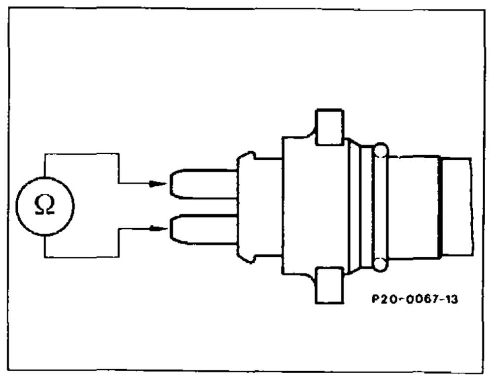
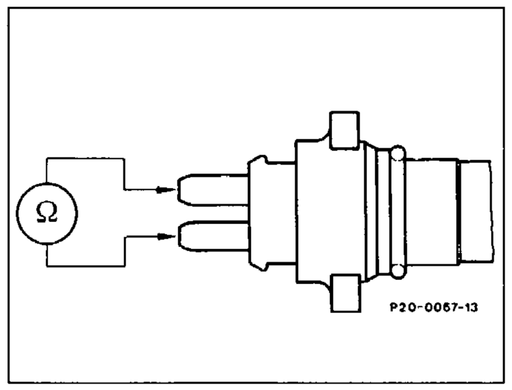
| Test coolant level sensor. Detach connector. Connect both pins to multimeter and test resistance. Readout: ~ 2 | ||||
| Yes | No | |||
| Vv | ||||
| Renew coolant level sensor. | ||||
eile §=RA 20.1044-440/7
Vv
| Check cable. Remove instrument cluster. Test contact 12 of 15-pin connector to ground with multimeter. Readout: © Q | |||||
| Rectify short to ground. | |||||
| —w. | Wo | ||||
| Renew qauge. | fenew gauge. | ||||
| v | |||||
| End of test | ‘nd of test | ||||
| B. | Indicator lamp does not light up when key in position ”2”. | ||||
| Check operation of bulb. | yheck operation of bulb. | ||||
| Yes | No | ||||
| “Renew bulb. | |||||
| Vv | |||||
| Remove instrument cluster. Measure voltage at contacts 6 and 9 of 15-pin connector with multimeter. Readout: approx. 12 V | |||||
| Yes | No | ||||
| Rectify open circuit according to wiring diagram. | |||||
| Vv | |||||
| Renew gauge. | Renew gauge. | ||||
| VW | |||||
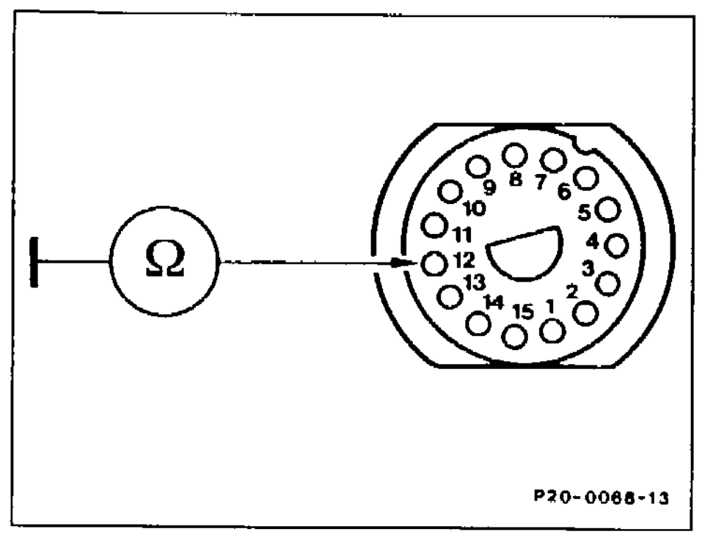
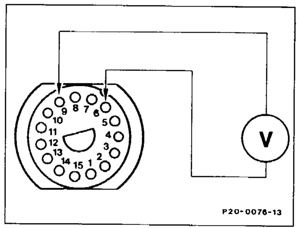
End of test
C. Indicator lamp does not light up when
engine running and coolant level below
*min”. Control function section „B” in
order.
| Check coolant level sensor. Detach connector. Connect both pins to multimeter and test resistance. Readout: approx. 5 2 | ||||||
| Yes | No | |||||
| Renew coolant level sensor. | ||||||
| Vv | ||||||
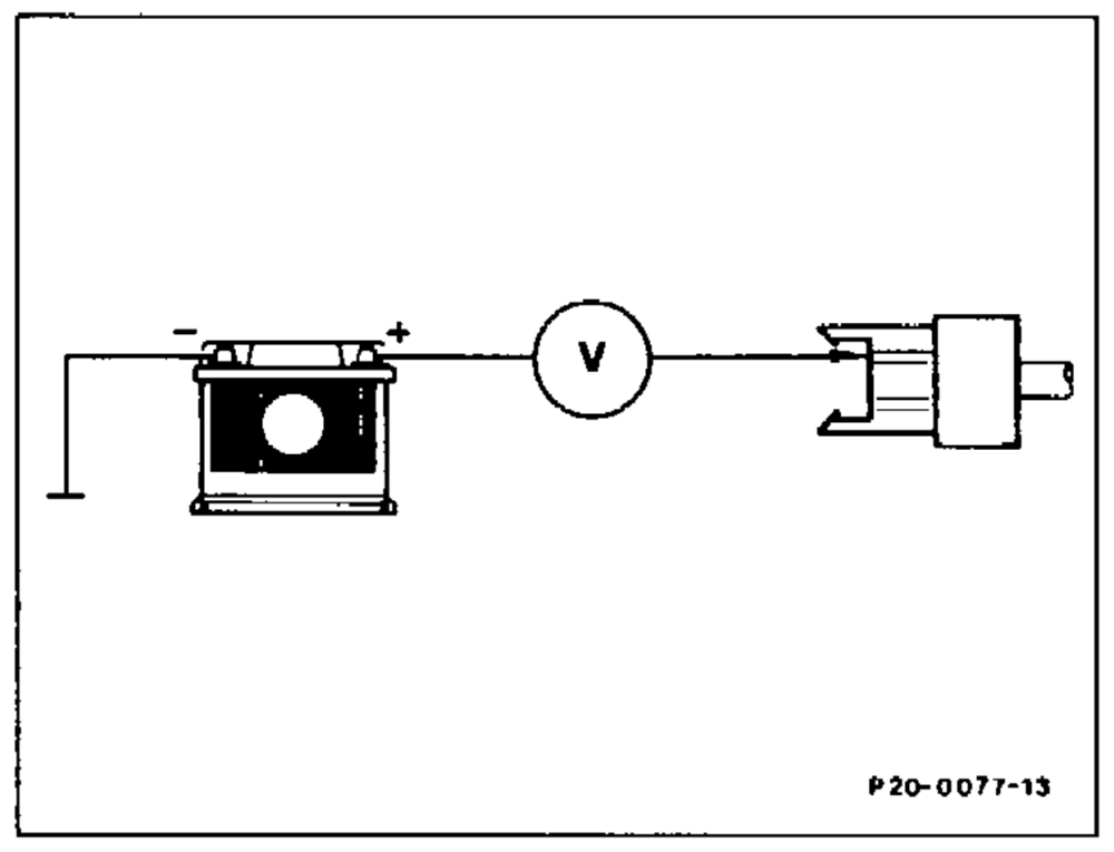
| Check cable. Connect multimeter to 2-pin coolant level sensor connector (brown cable) and battery positive. Readout: approx. 12 V | ||||||
| Yes | No | |||||
| Vv | ||||||
| Test ground connection, correct if necessary. | ||||||
| Vv | ||||||
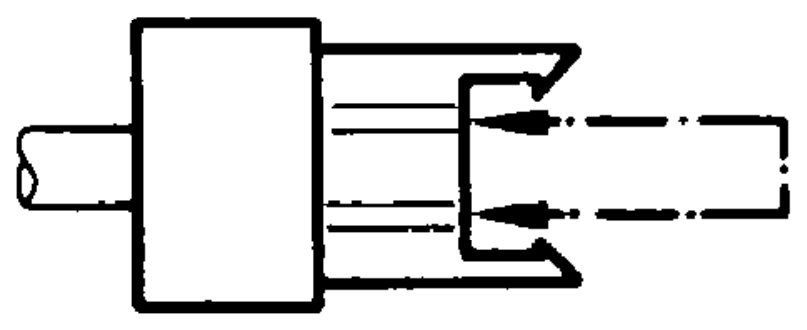
| Jumper coolant level sensor connector. With key in position „2”, indicator lamp should fight up. | = in postion „2” near lamp shoul fo | |||||
| Yes | No | |||||
| Vv | ||||||
| Rectify open circuit according to wiring diagram. | ||||||
| Vv | P20-0078–13 | |||||
| End of test | =nd of test | |||||