Temperature-controlled viscous fan coupling
WIS 20-310
Function
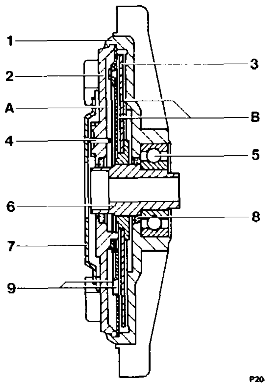
The viscous fan coupling is a maintenance-free hydraulic coupling which operates steplessly dependent on temperature.
When the engine is started (cold start), the fan runs initially at a higher speed until the oil has flowed back from the working chamber (8) into the storage chamber (A). Following this, the fan coupling switches off. Fan speed in the off state depends on engine speed. Fan speed, however, does not exceed 1000 rpm.
This state is maintained for as long as the engine has not yet reached the cutin temperature. P20-0007–15
Coupling body (secondary part) DPpemvanmauona Cover Driving plate (primary part) Switch pin Baill bearing Bearing bush Bimetal strip Seal Valve Storage chamber Working chamber
tie §=RA 20.1044-310/1
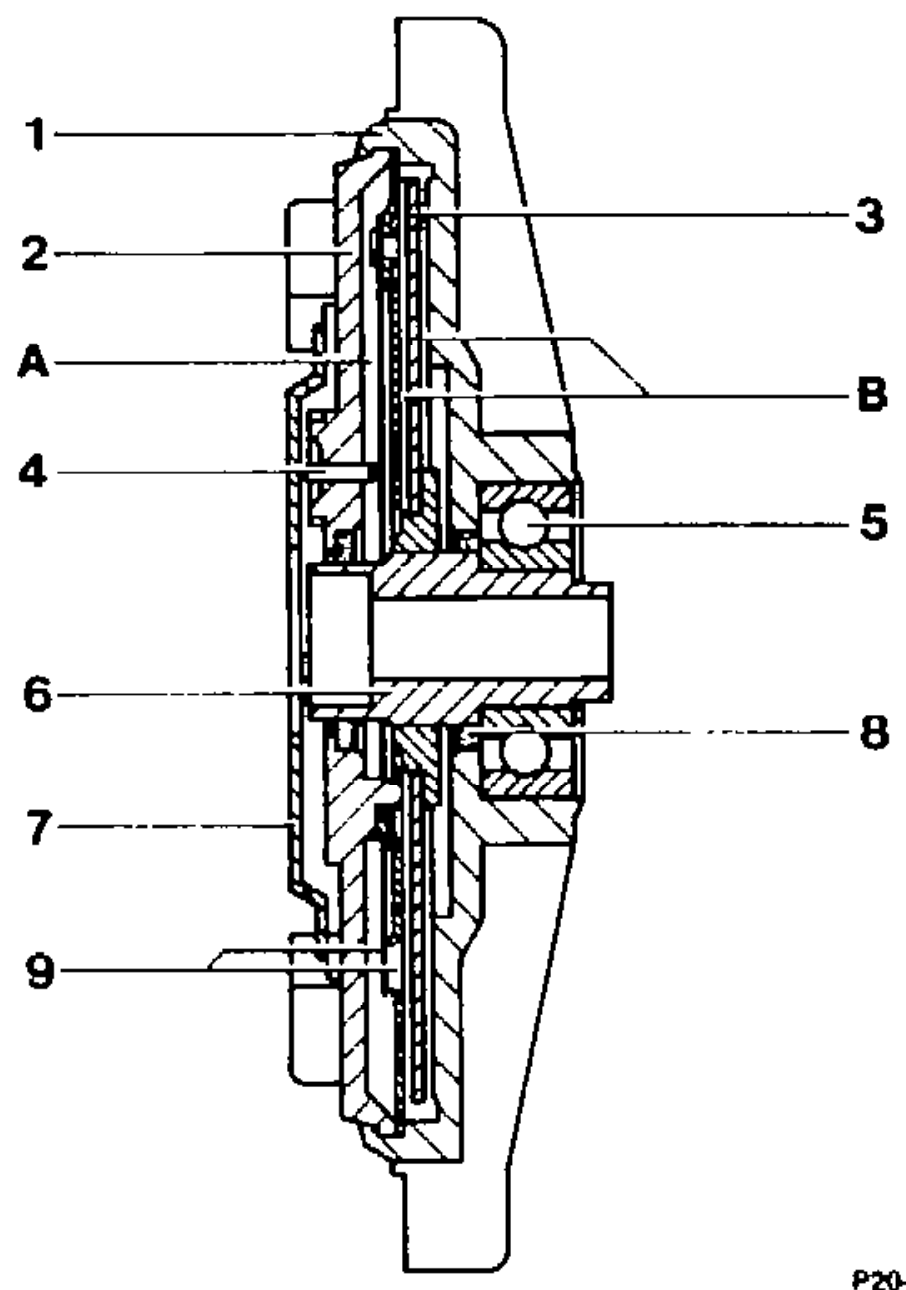
If the coolant temperature rises because of higher engine load or high outside temperatures, the air which flows through the radiator and impinges on the bimetal strip (7), becomes warmer. The bimetal strip (7) alters its shape as it heats up and opens a valve (9) at approx. 71 °C by means of a pin (4) and thus also the passage for the oil from the storage chamber (A) into the working chamber (B), which causes the fan to cut in.
The coolant temperature during this switching operation is between approx. 90 and 95 °C.
When the coupling is engaged, fan speed increases somewhat proportionally with increasing engine speed in the lower rpm range, without exceeding 3300 rpm in the upper. P20-0087–15
Checking cut-in temperature
Run engine at 4000 — 5000 rpm. Once a coolant
Coupling body (secondary part) Dremrnnron temperature of approx. 90 – 95 °C has been Cover Driving plate (primary part) reached, the speed of the viscous fan coupling Switch pin must increase, which can be clearly heard. Ball bearing Bearing bush Bimetal strip
Repairs
Seal It is not possible to repair a faulty coupling; it Valve Storage chamber should always be renewed. Working chamber
Transportation and storage
Temperature-controlled viscous fan couplings must be transported upright. For brief periods — e. g. for installation purposes, the coupling may be placed on the flange side, but never on the front side.
AN The bimetal strip must not be bent or damaged.
wie §=RA 20.1044-310/2
Distinguishing features
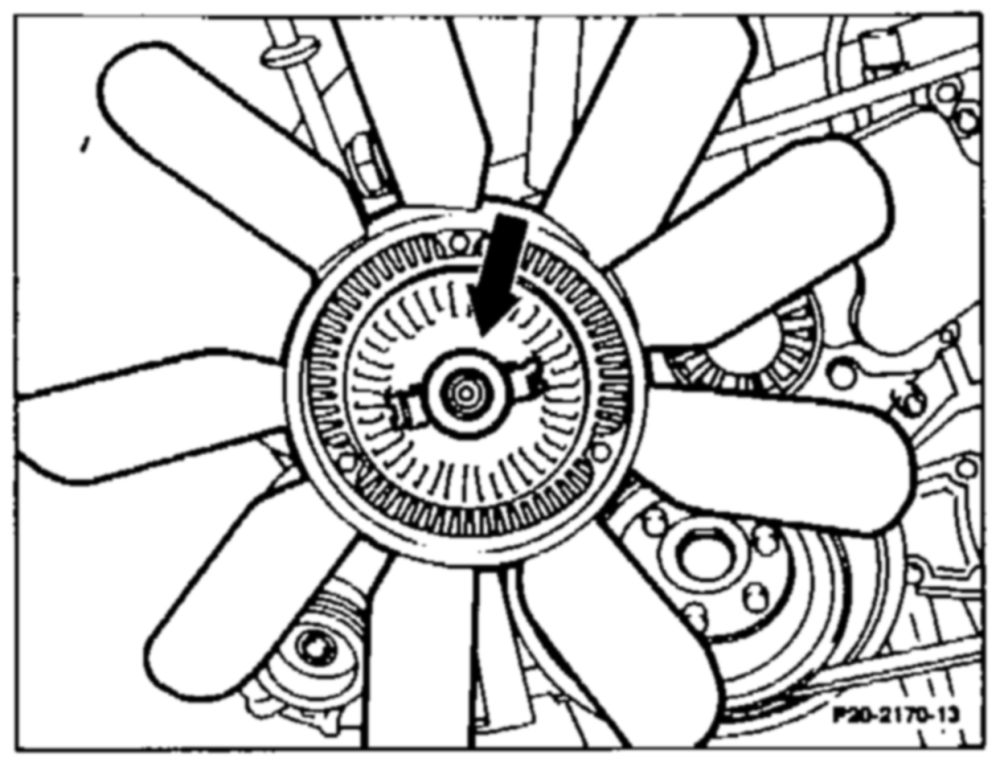
Engines 602.911/912 and 603.912 bimetal spring; color silver grey. Imprinted part no. 603 200 00 22 (arrow).

The viscous fan couplings of engine 602.96 and 603.96 have been strengthened because of the enlarged fan. Bimetal spring; color metal-colored. Red imprinted part no. 603 200 00 22 or 603 200 04 22.
P20-2174–12
Engine 601 in model 202
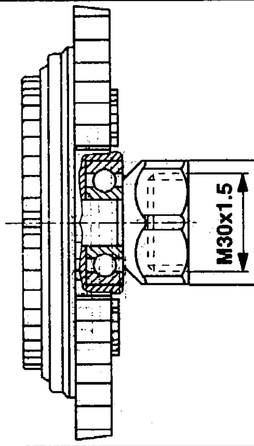
On this engine the viscous fan coupling is bolted onto the coolant pump shaft with a union nut, waf 36 mm and left-hand thread.
Cut-in temperature: 90° at 4000 rpm Identification: part no. 604 200 00 22 imprinted on bimetal spring and white color dot.
P20-5372–15