Notes regarding coolant pump
WIS 20-215
General
The coolant pump located at the bottom right of the engine is attached to a light alloy housing bolted to the crankcase. The coolant thermostat (318) is likewise contained in this housing.
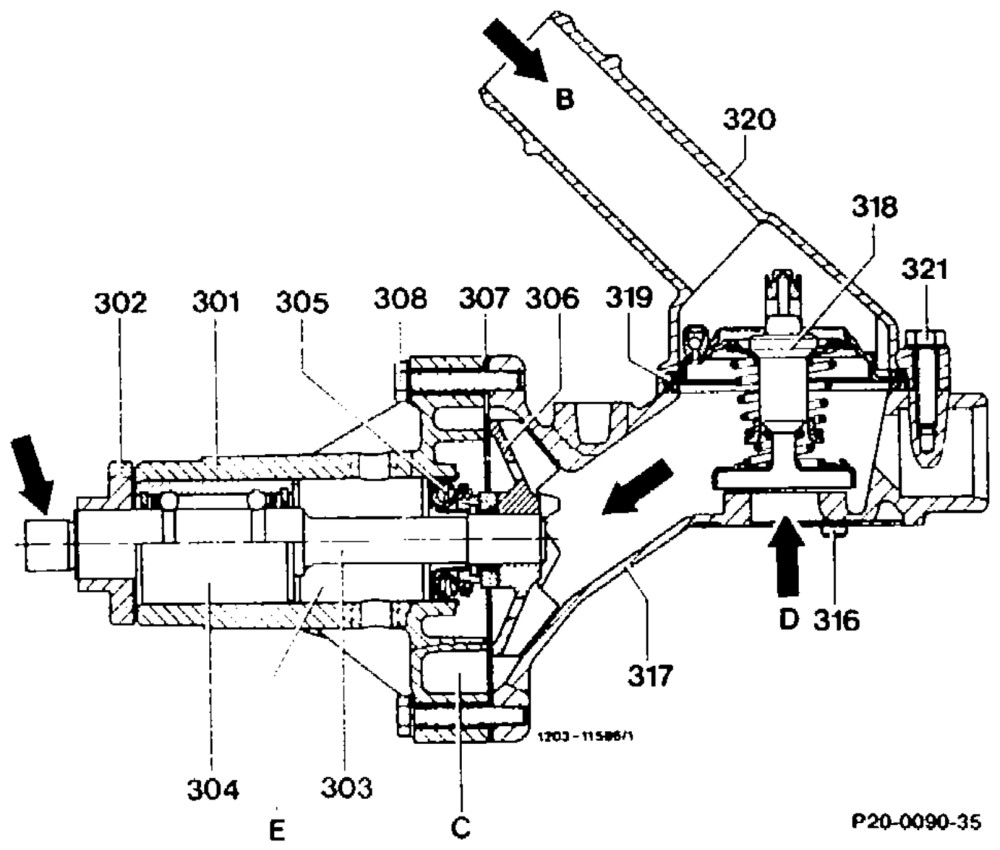
A flange (302) is pressed onto the coolant pump shaft (303) for attaching the belt pulley. The deformation space (E) is located between coolant pump bearing (304) and cassette seal (305). The fan is attached at the stub end (arrow).
301 Coolant pump housing 302 Flange 303 Coolant pump shaft 304 Coolant pump bearing 305 Cassette seal 306 Impeller 307 Gasket 308 Hexagon bolt M6Xx35 316 Fit pin 317 Light alloy housing 318 Coolant thermostat 319 Gasket 320 Inlet connection mogga inlet connection to radiator Pump chamber Inlet from crankcase Deformation space
RA 20.1045-215/1
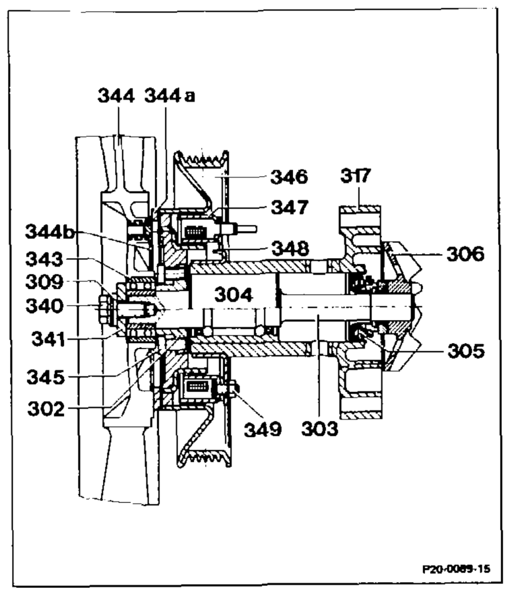
Engine 601 Arrangement of magnetic fan coupling and coolant pump
301 Coolant pump housing 302 Flange 303 Coolant pump shaft 304 Coolant pump bearing 305 Cassette seal 306 impeller 309 Tensioning disc 340 Collar bolt 341 Washer 343 Ball bearing 344 «Fan 344a Armature 344b Leaf spring 345 Hexagon bolt M 6×12 346 Belt pulley 347 Magnet body 348 Magnet camer 349 Hexagon nut
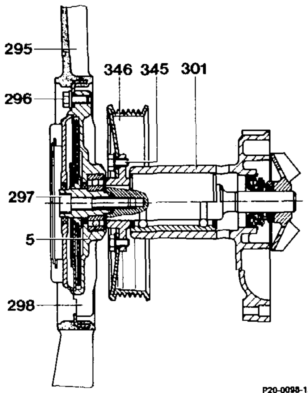
Engines 601 (only in model 124), 602 and 603 Arrangement of viscous fan coupling and coolant pump
5 Ball bearing 295 Fan 296 3 bolts M 6×14 297 Hexagon socket screw M 10×40 298 Viscous fan coupling 301 Coolant pump housing 345 4 hexagon bolts M 6×12 346 Belt pulley
Engine 601 in model 202
On this engine the viscous fan coupling is bolted onto the coolant pump mount by a union nut with left-hand thread.
RA 20.1045-215/2
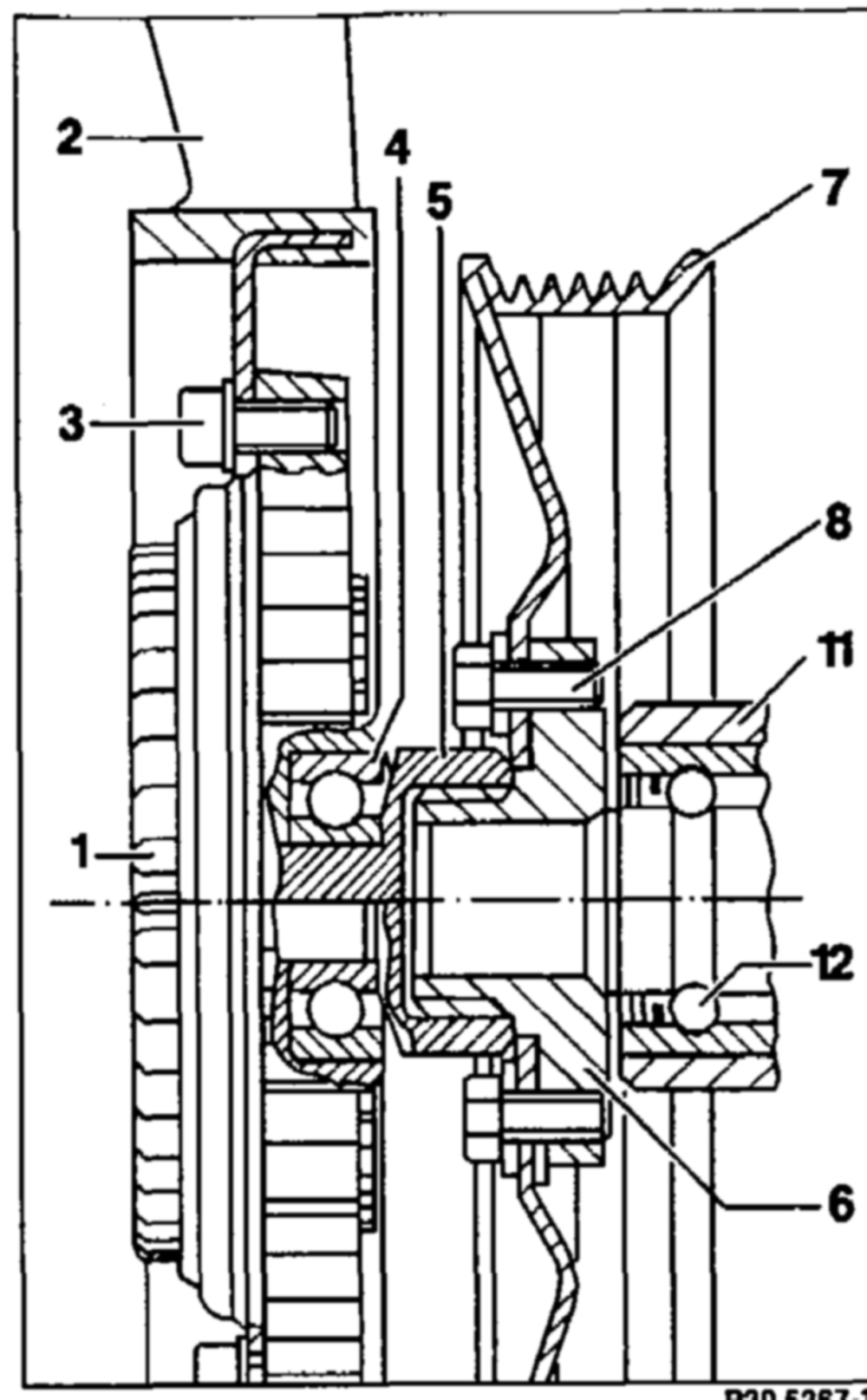
Engine 601 in model 202
Arrangement of viscous fan coupling and coolant pump
1 Viscous fan coupling Fan © Pf ane Bolt + washer, 10 Nm Ball bearing Union nut, waf 36 mm Left-hand thread, 45 Nm Flange ONO ~o Belt pulley, dia. 168 mm Hexagon bolt + washer M6 x 10, 10 Nm Coolant pump housing Coolant pump ball bearing ny P20-6267-17
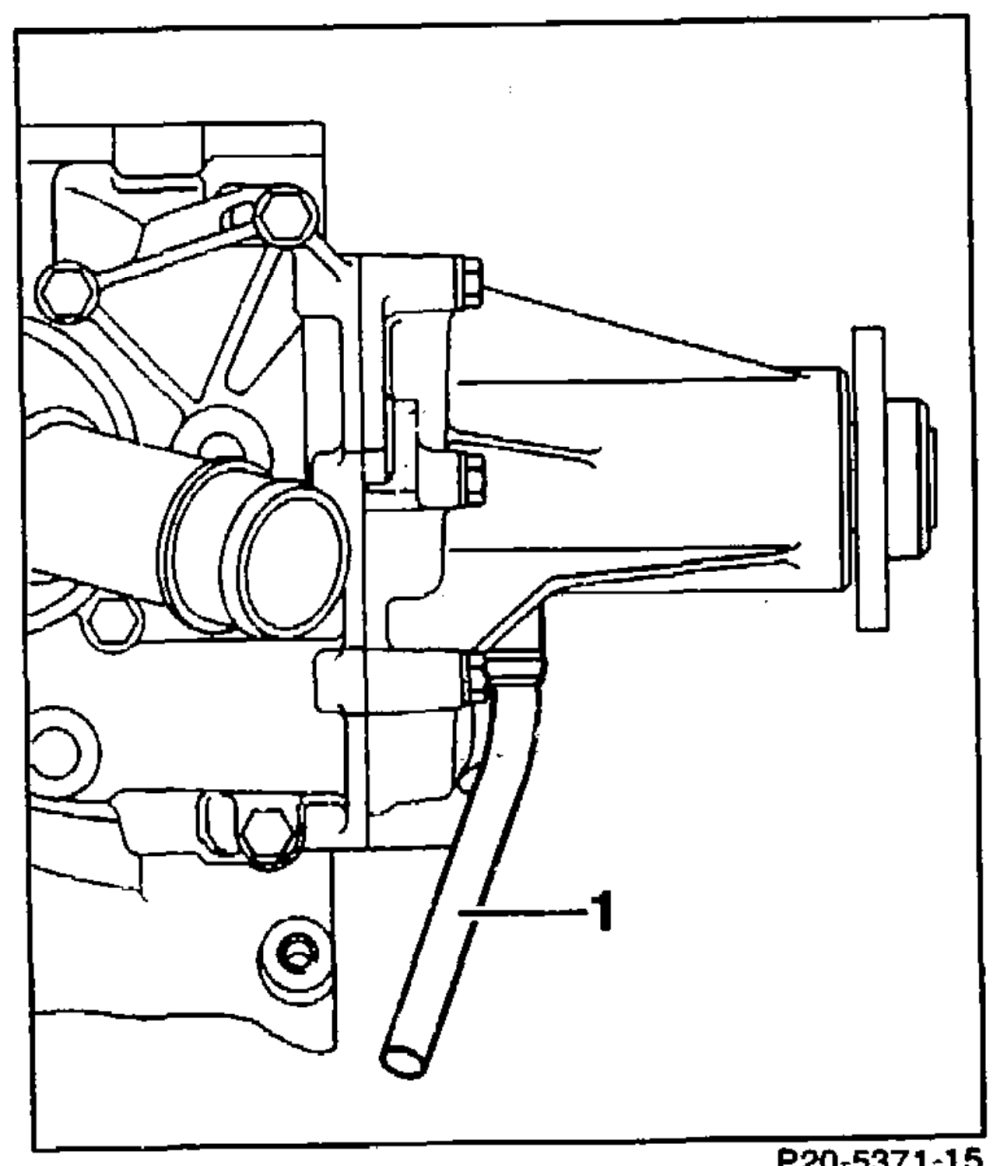
Coolant pump with drainage pipe
Since 01/92 coolant pumps with a drainage pipe (1) have been installed. This channels off any coolant which may flow out occasionally from the vent hole in the coolant pump housing. This thus eliminates any residue smears in the directly visible area.
The coolant pump should only be replaced if coolant is found in the expansion tank as result of a leak in the coolant pump.
Coolant pumps for installation of drainage pipes are supplied through the parts sector. When installing, always install or replace the drainage pipe at the same time.
The drainage pipe can also be retrofitted. See Programmed Repairs for operation instructions.
RA 20.1045-215/3
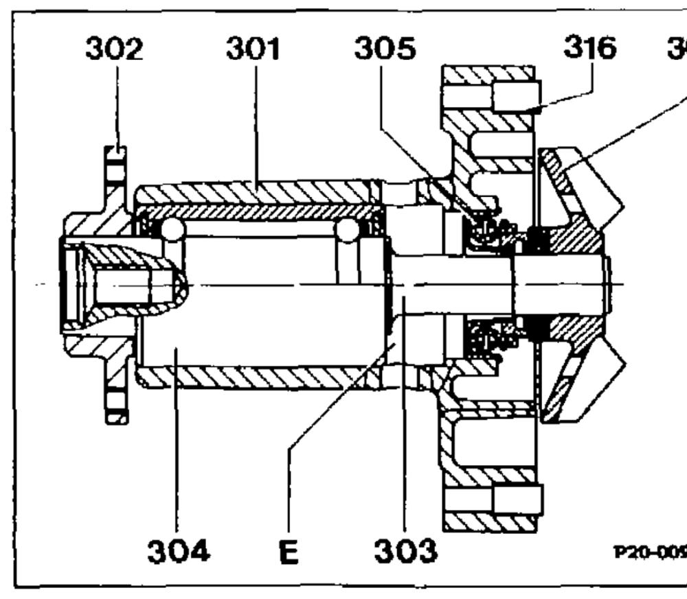
a8 The coolant pump of engines 602, 603 as of start of production, of 601 in model 124 as of 02/92, is strengthened at the coolant pump housing (301) and at the coolant pump bearing (304) because of the heavier viscous fan coupling.
The diameter of the impeller (306) on all the engines is identical.
The coolant pump shaft has a tapped hole M10 X 22 at the front for attaching the viscous fan coupling. 301 Coolant pump housing 302 Flange From 06/89 up to 11/88 a plastic impeller was 303 Coolant pump shaft 304 Coolant pump bearing fitted to engines 601.911/912. 305 Cassette seal 306 Impeller 316 Fit sleeve —E Deformation space
Engine 603.971
Since 09/95 a coolant pump with a larger impeller has been installed in this engine. This increases the volume flow in the cooling system.
Previous impeller @ 68 mm Present impeller @ 72mm
RA 20.1045~-215/4