Testing electronic diesel system (EDS)
WIS 07.1-1120
Preceding work: Operation no. of operation texts and work units or standard texts and flat rates: 07-1120
Engine 602.96, Model 201 Gs4) Federal Model Year 1987 OanmMoon> Engine 603.96, Models 124 and 126 Gs Federal and California Model Year 1986/87 Engine 603.96, Model 124 CG) Model Year 1988 Engines 602.96 and 603.96, Models 124 and 201 CA) CG) Model Year 1989 Engines 602.96 and 603.96 CA) Model Year 1990 and GN) Model Year 1991 Engines 602.962 and 603.970, @s4 Model Year 1990 Engines 602.96 and 603.96, Models 124 and 201 Basic Version Code 62/0, CAD Gi) GD GO) GD) as of Model Year 1992 Engine 603.971, Model 140 Gsé Model Year 1992 =
Test conditions Coolant temperature approx. 80 °C Air conditioner: OFF Selector lever position ”P” Fuse at overvoltage protection relay or base module (engine 603.971) in order Battery voltage approx. 12 volts at overvoltage protection between contacts 1 and § or engine 603.971 battery voltage approx. 12 V at EDS control unit between contact 1 and contact 14.
Note engine 603.971 Before reading the stored faults by means of the pulse output, the battery must on no account be disconnected, base module and EDS control unit (N39) must on no account be unplugged.
gti = RA 07.1.1042-1120/1
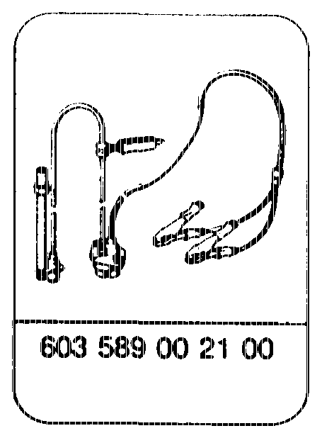
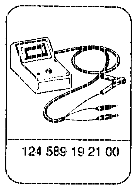

in, DIT 9000, DMA1000 Sun, MEA 1500 All-Test, 3610-MB Hermann 421, MO941, D960 sch, MOT 002.01, MOT 103, 301/401
Y distributor 117 078 01 45
Ma, Sy
Lambda control tester Bosch KDJE-P600 Hermann L115
agian = RA 07.1.1042-1120/2
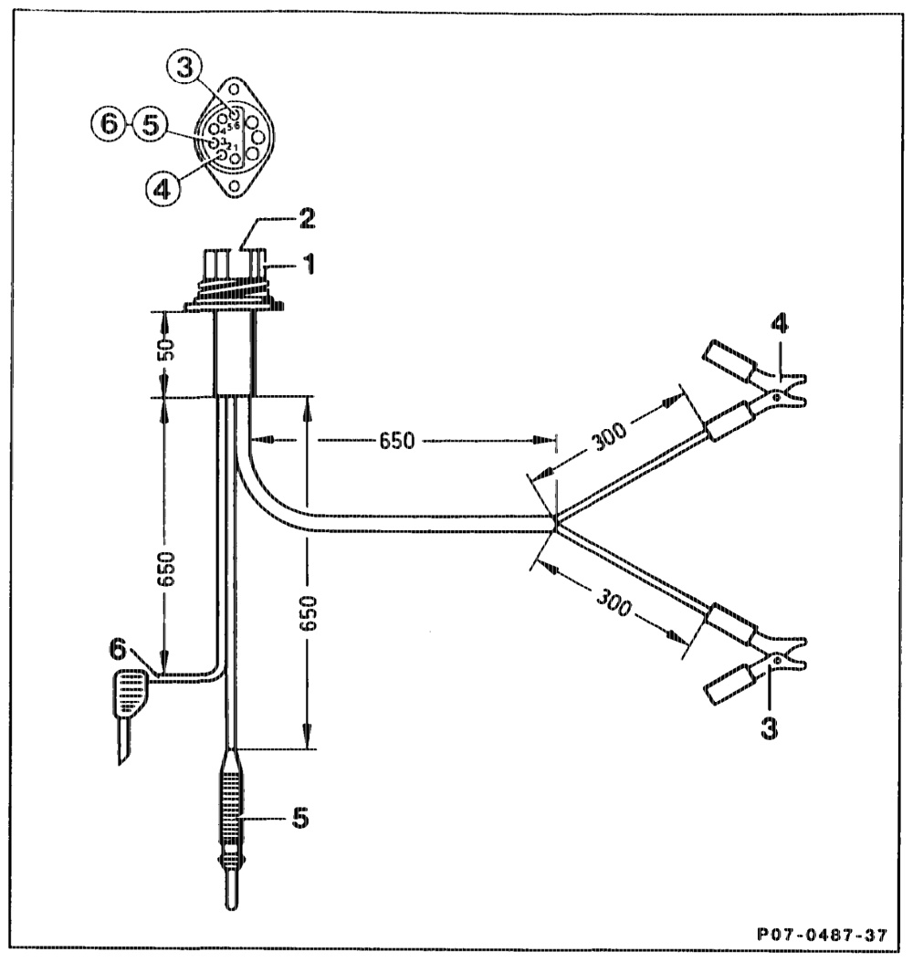
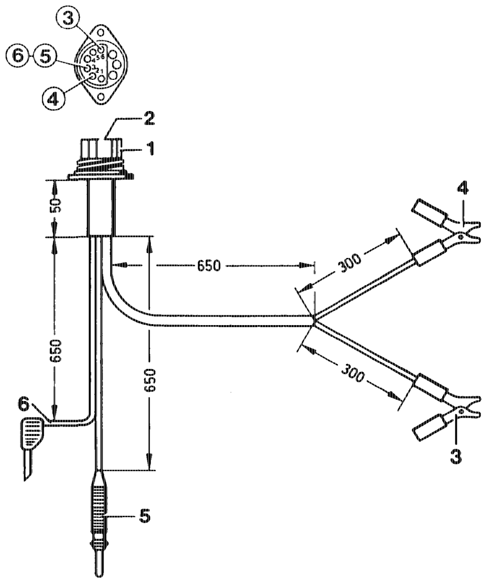
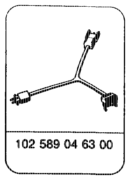
Test cable shop-made
Test cable (X11)
Pin assignment of test socket Position 3 to jack 6 Position 4 to jack 2 Pasition 5 to jack 3 Position 6 to jack 3
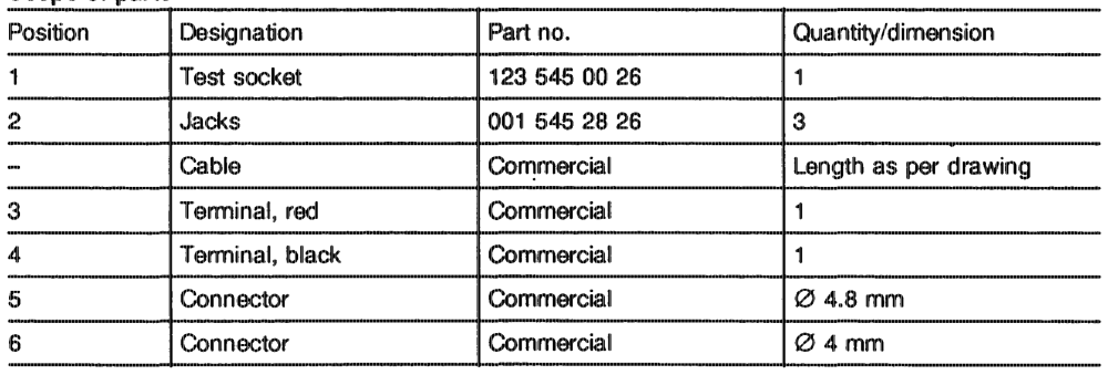
Scope of parts
otihiyn = RA 07.1.1042-1120/3
A. Engine 602.96, Model 201 Federal Model Year 1987
a) Short-test b) Testing components c) Testing electronic idle speed control
a) Short-test
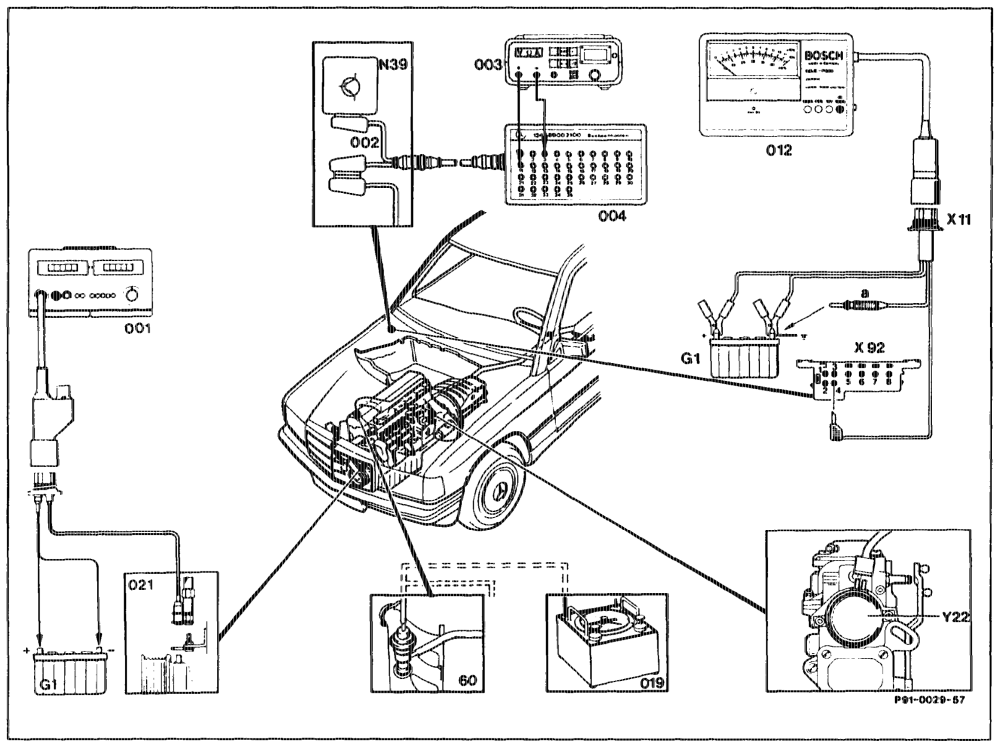
Digital tester (001) and pulse counter (021) ….. connect, disconnect. Lambda control tester (012) 6… ee ee ee ee eee connect to battery (G1) and test connector (X92). Connect, disconnect, press 100 % IR switch.
apttis = RA O7.1.1042-1120/4
Contact box (004) ) 2… eee ee connect, disconnect with test cable (002) to EDS control unit (N39). Vacuum tester (019) 2.2.2.0… 0.0… .00008connect, disconnect with Y distributor at ARF valve.
Digital tester (003) 2… eee connect to contact box (004), disconnect. Fuse at overvoltage protection (K1/1) ……… test.
Selector lever… eee ee eee move into position ”P”. Air conditioning/automatic climate control …… switch off. ENgine 2… cece ee eee ee eee bring to operating temperature (coolant temperature to 80 °C).
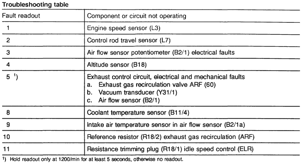
Note When performing the test work, the air intake hose between the air flow sensor and exhaust gas turbocharger must be fitted, otherwise no signal will pass from the air flow sensor to the EDS control unit (N39). Connector „a” wk ee eee ee eee hold approx. 1 second to battery ground 100 % readout. Connector „a” ee ee eee take off. 0 % readout, no fault in system. Readout fluctuates, fault in system (refer to troubleshooting table).
Note One pulse = 0% — 100 % -0 %.
The number of pulses indicates which electrical component is faulty.
Repeat test until there are no further pulses displayed.
eottiyn = RA 07.1.1042-1120/5
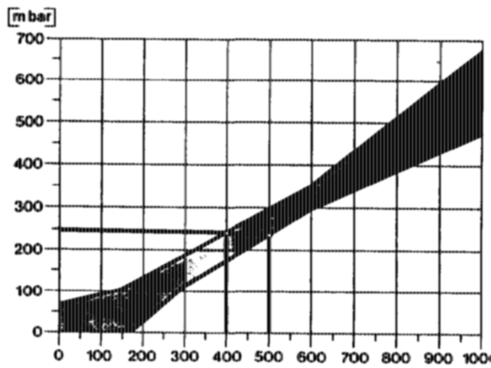
Double connector of ELR solenoid Y22 …….. disconnect and fit on again (at least 3 seconds). Engine speed increases briefly. Engine …….. See eee eee eee eee run engine at approx. 1200/min and approx. 250 mbar. Briefly apply full throttle. Vacuum drops to 0 mbar. ENgine 2… eee eee eee switch off. ARF valve oo… cee eee eee scenes see pressurize ARF valve with approx. 300 mbar vacuum. ARF valve is heard to close.
autihin = RA 07.1.1042-1120/6 b) Testing components
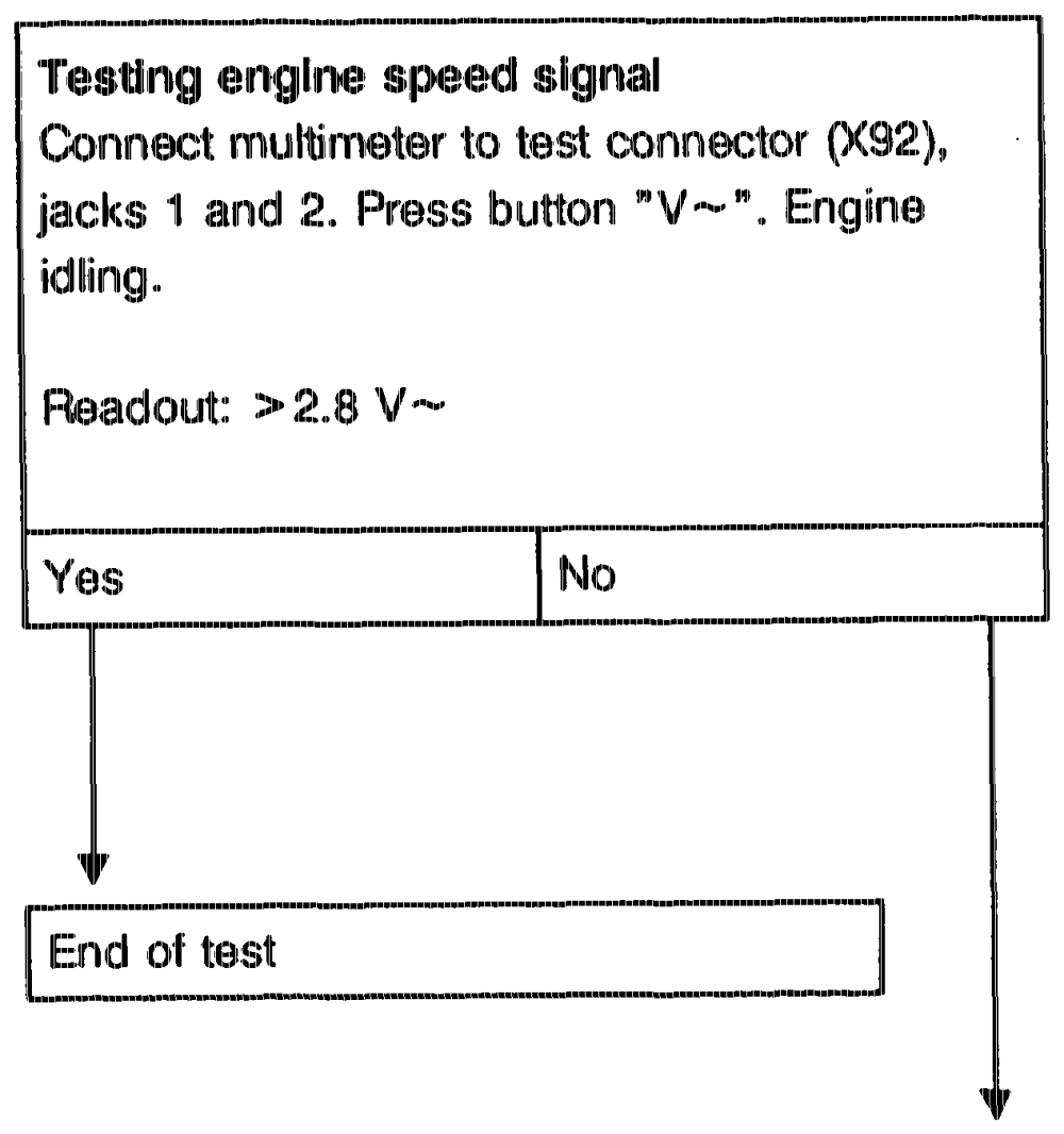
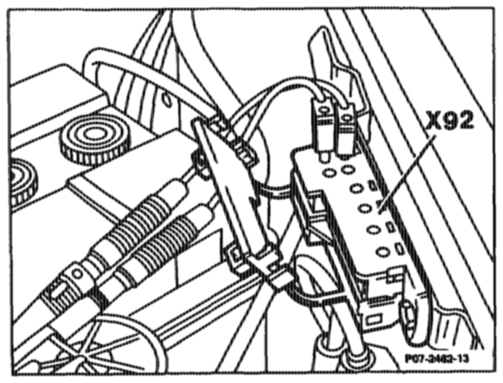
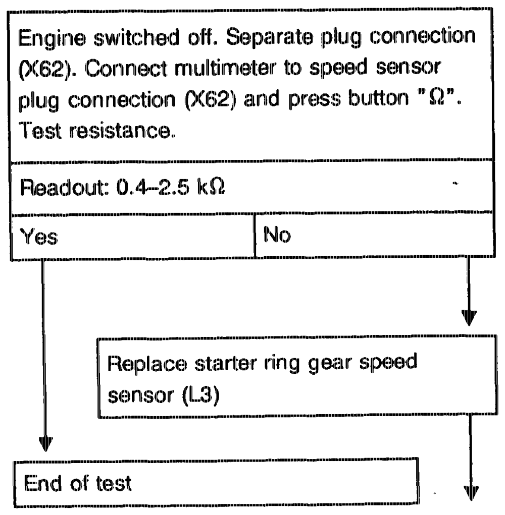
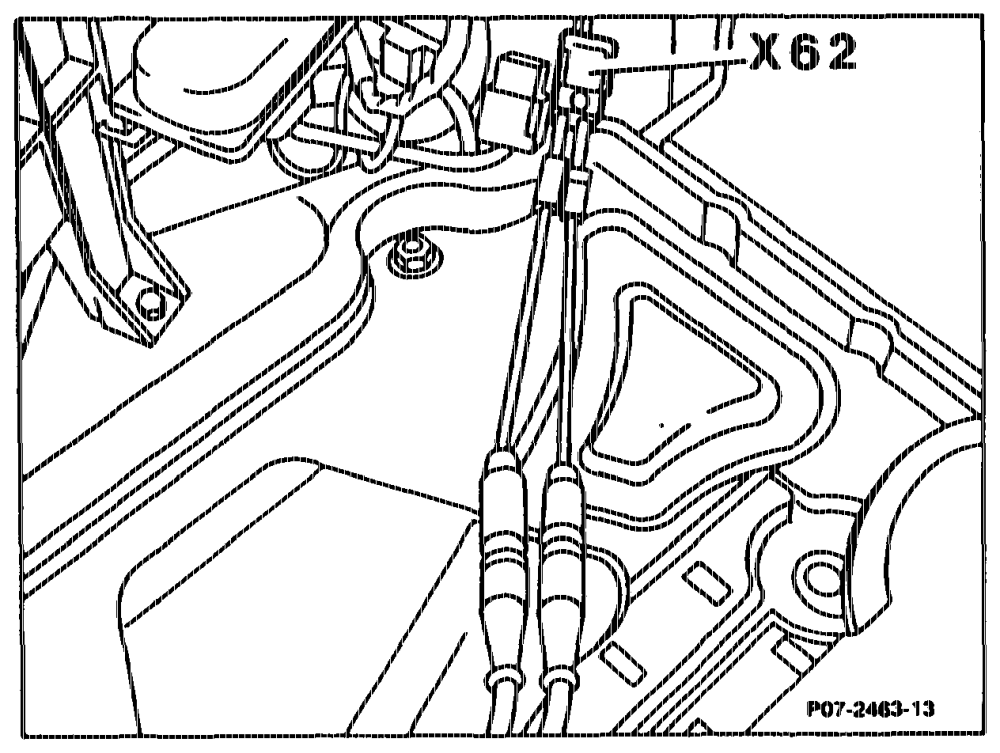
Fault readout 1”
aptihiyn = RA 07.1.1042-1120/7
quiihiy = RA 07.1.1042~1120/8
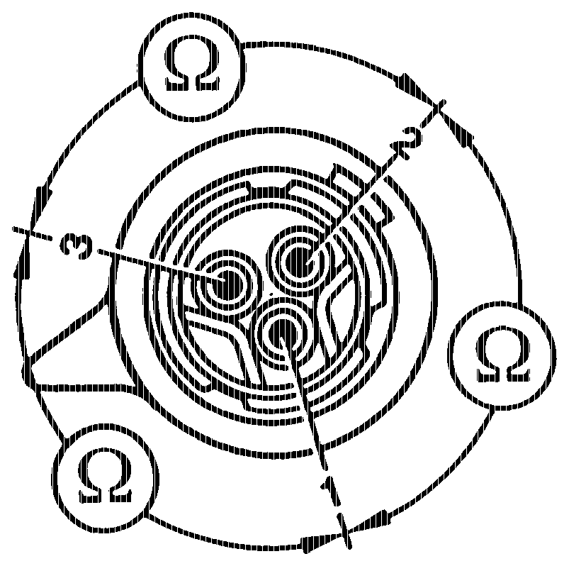
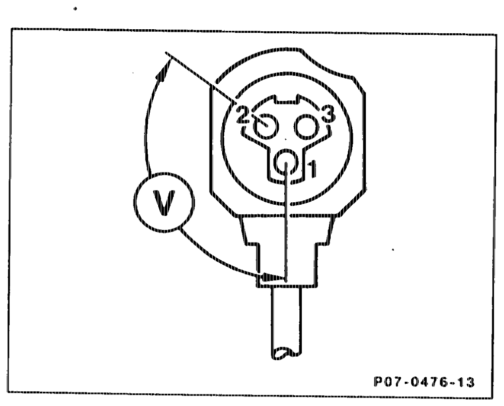
Fault readout „2”
apthiin = RA 07.1.1042~1120/9
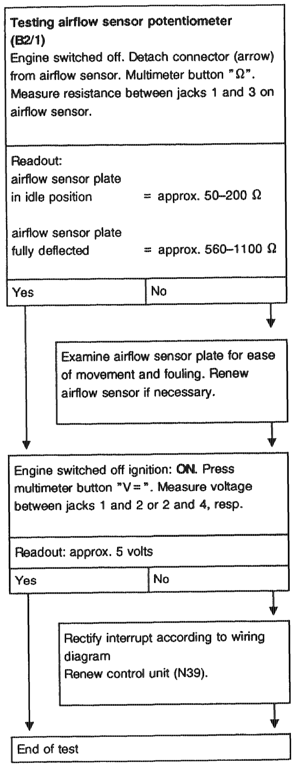
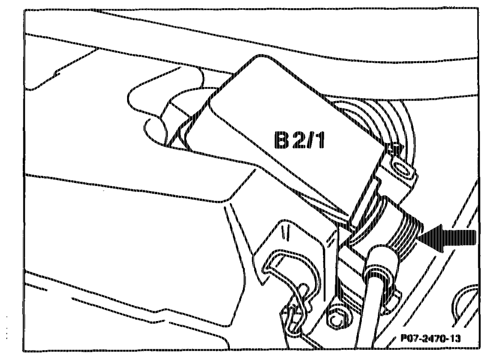
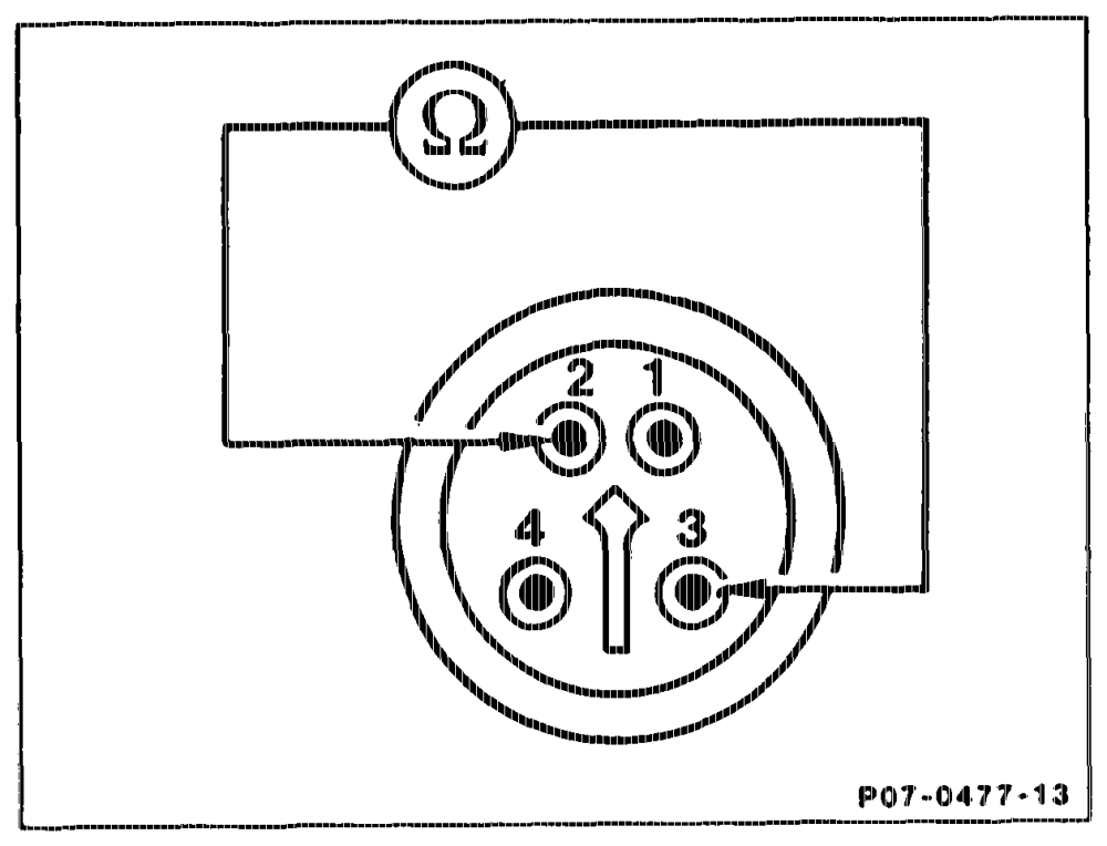
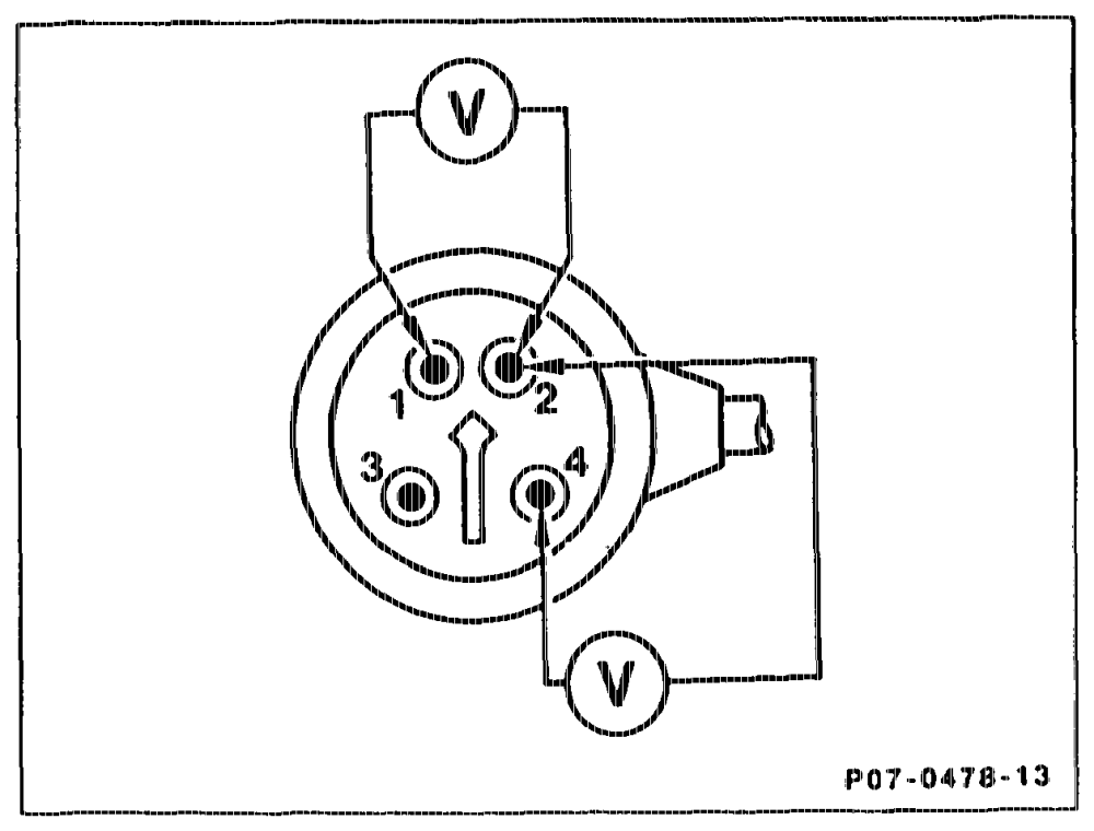
Fault readout opening ”3”
Note If airflow sensor removed, also perform „Tasting air temperature sensor (B2/1a)” (Fault readout 9).
apts = RA 07.1.1042~1120/10
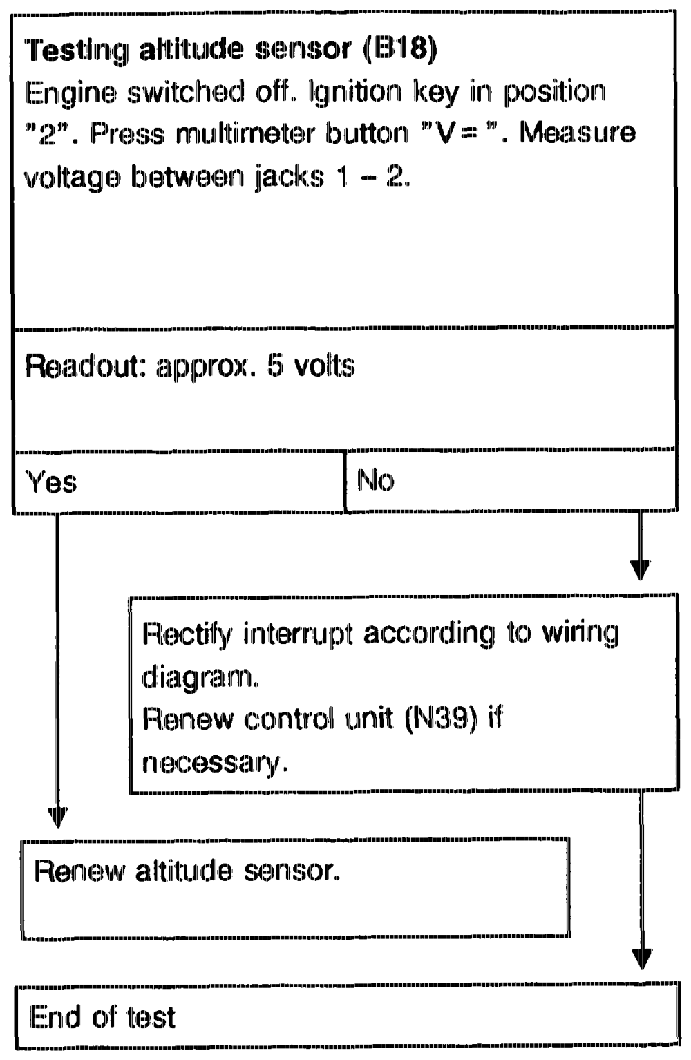
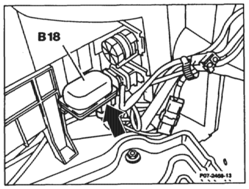
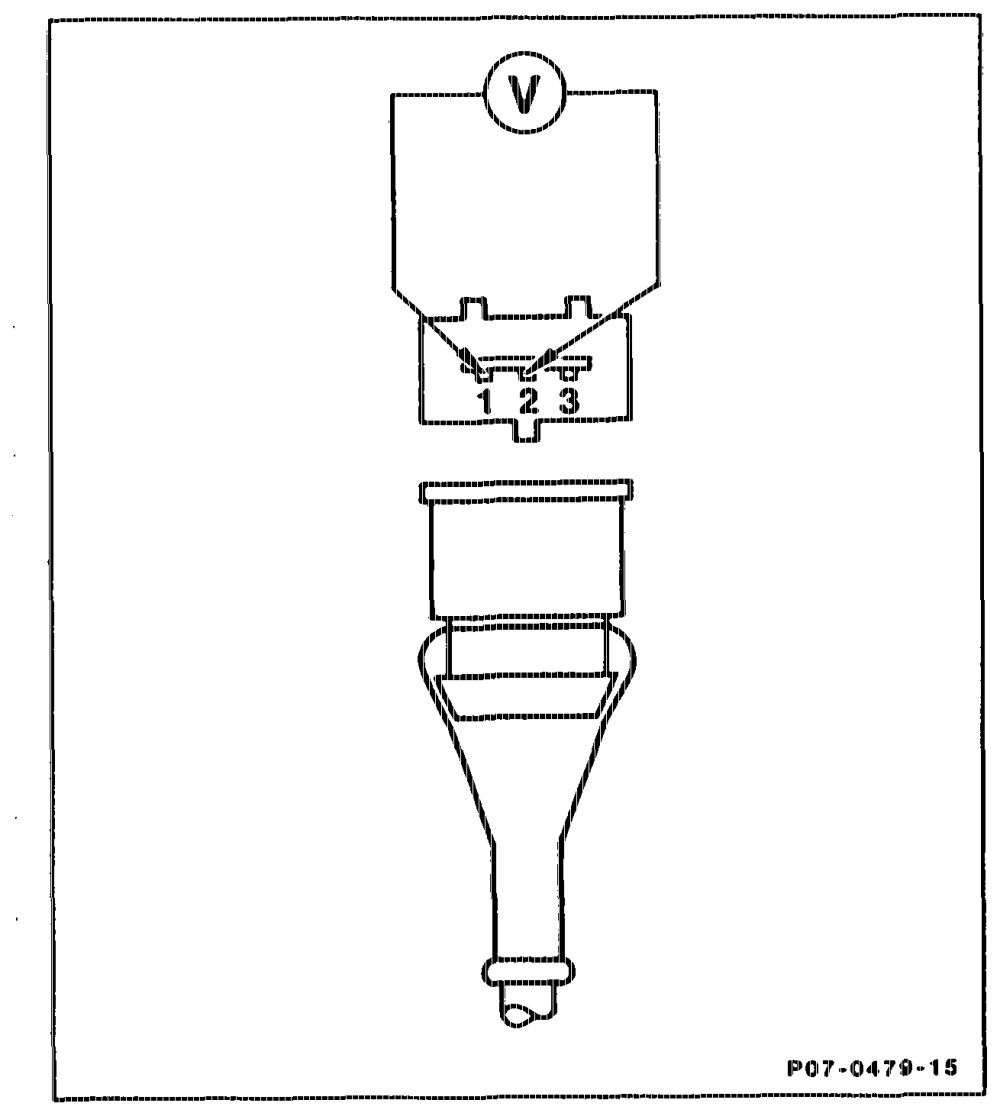
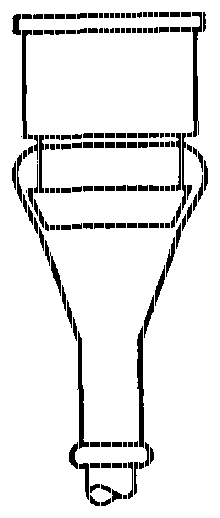
Fault readout ”4”
aptiie = RA 07.1.1042-1120/11
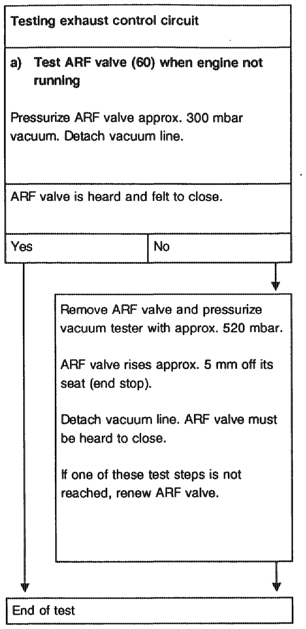
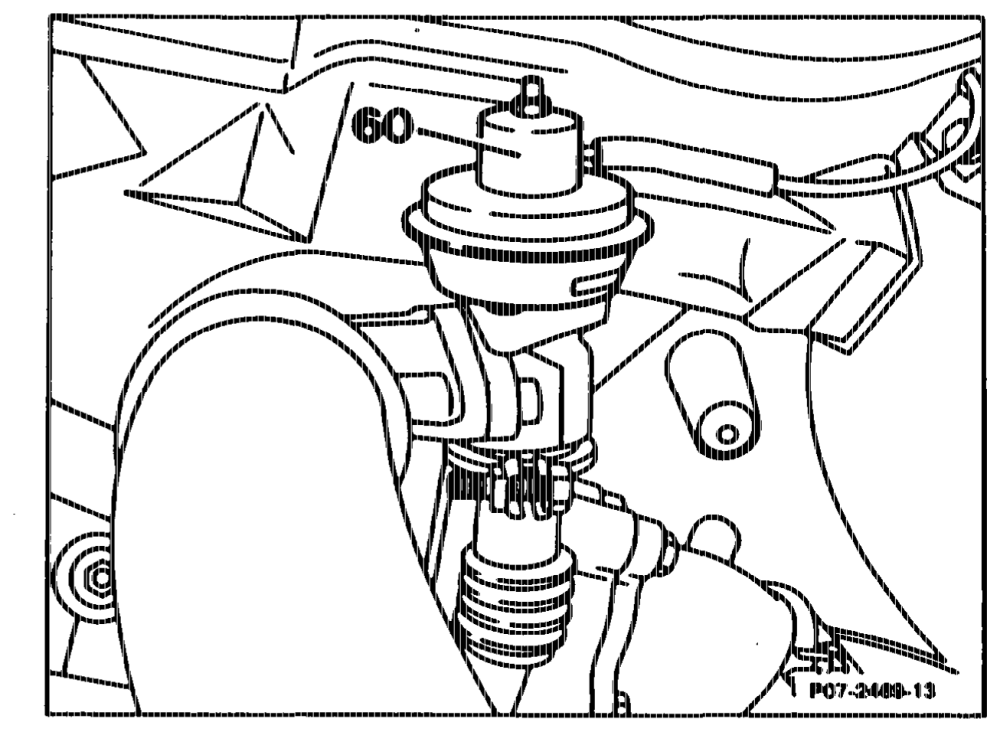
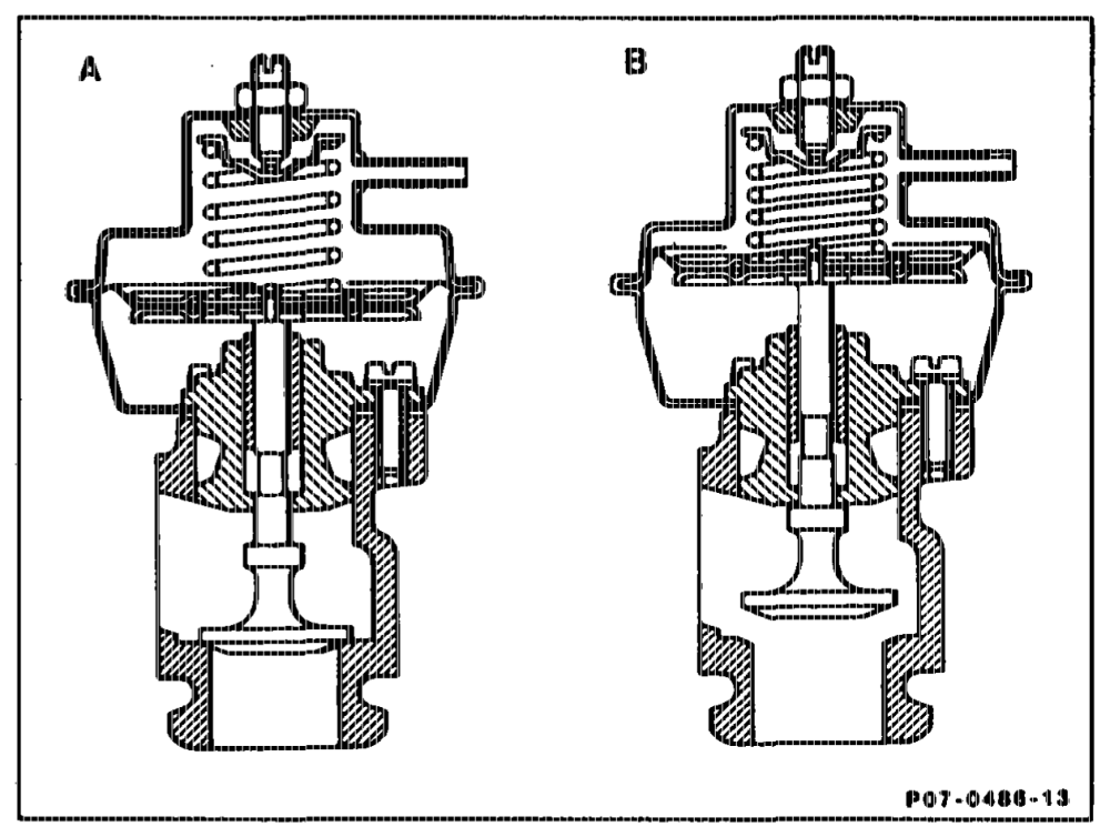
Fault readout ”5”
egittiy = RA 07.1.1042-1120/12
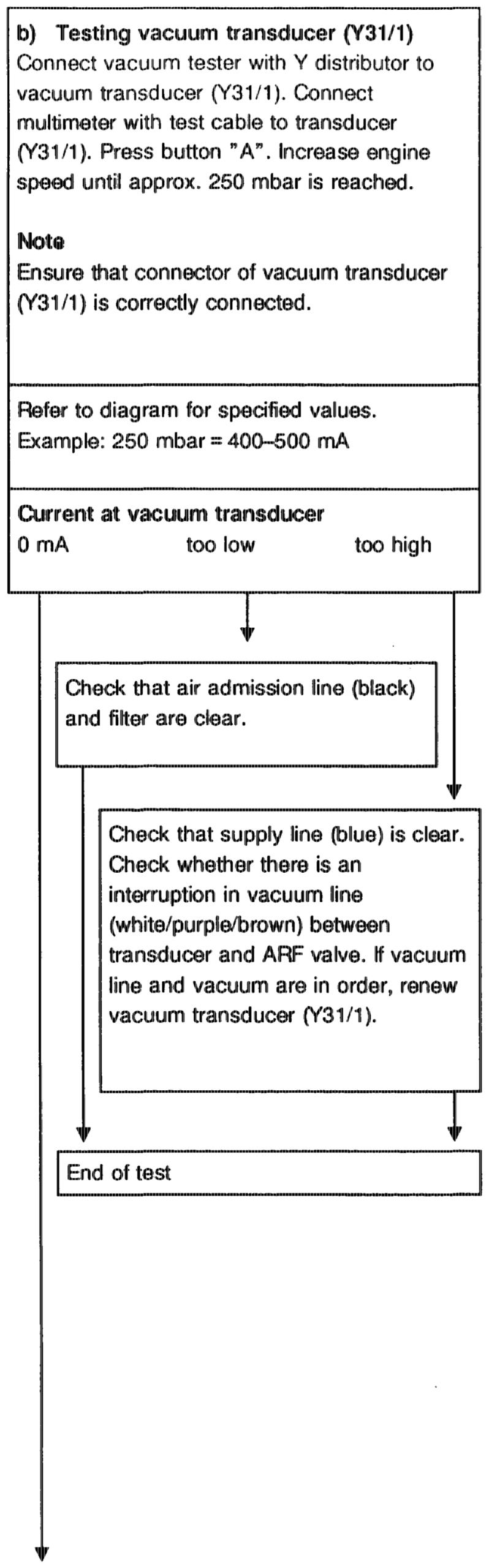
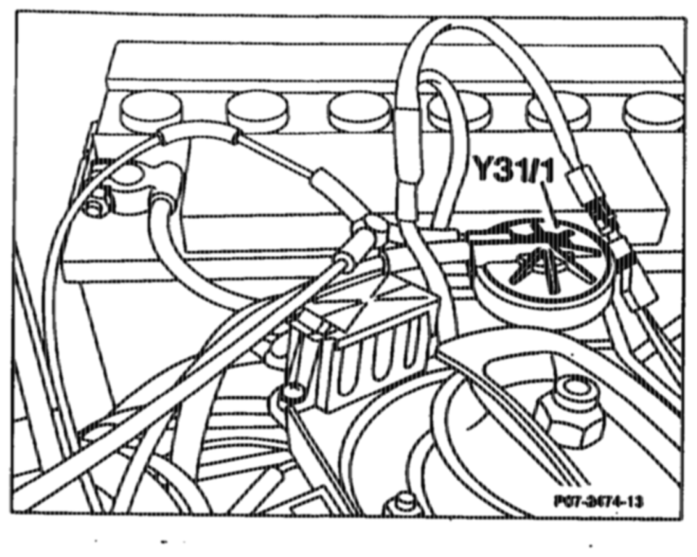
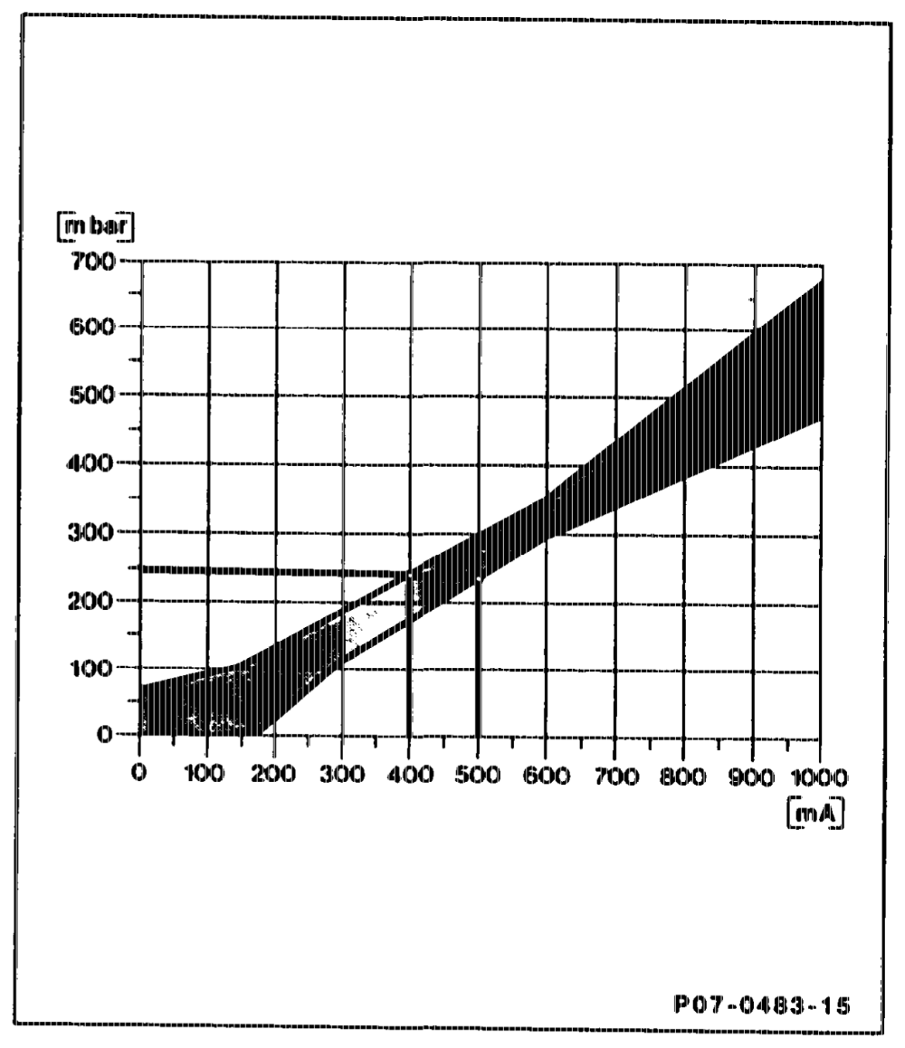
eptiajm = RA 07.1.1042-1120/13
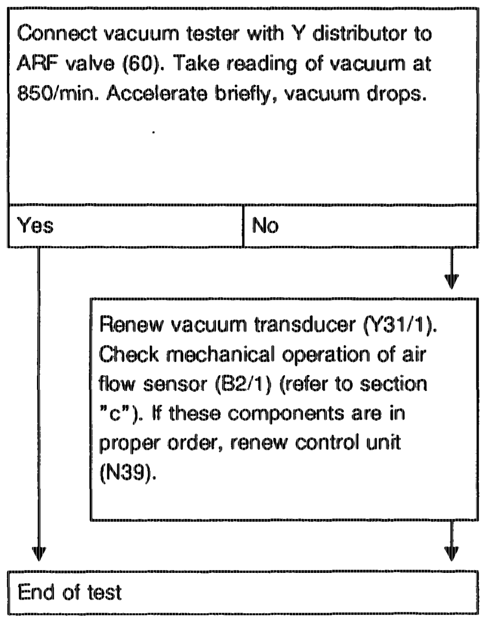
aptinn RA 07.1.1042-1120/14
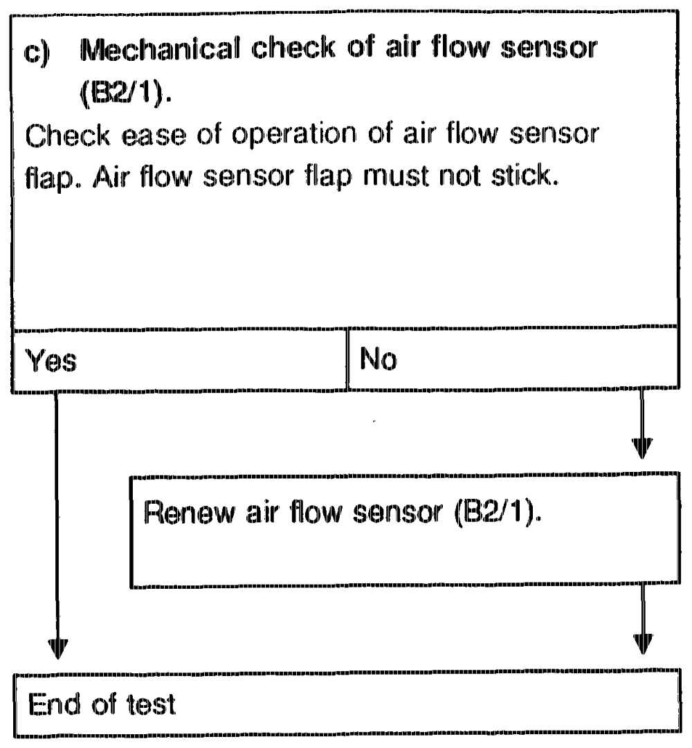
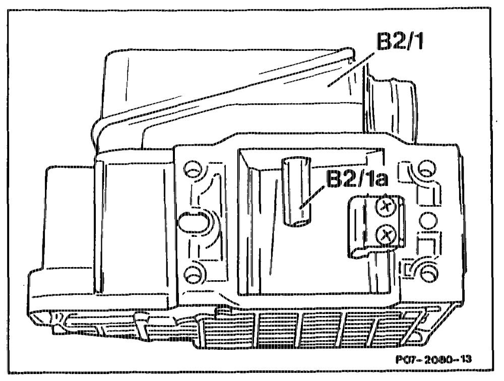
phi = RA Q7.1.1042-1120/15
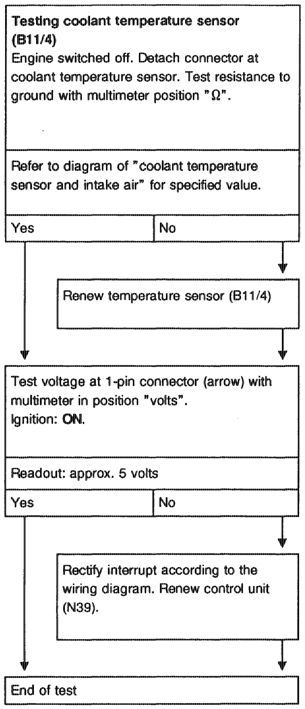
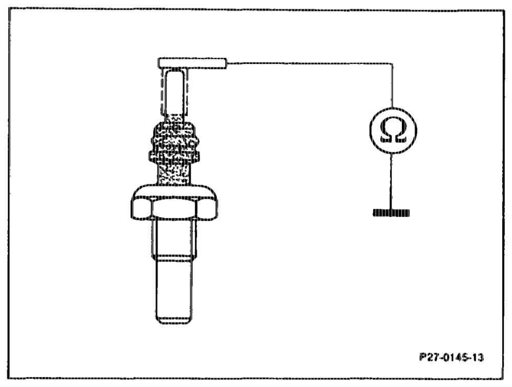
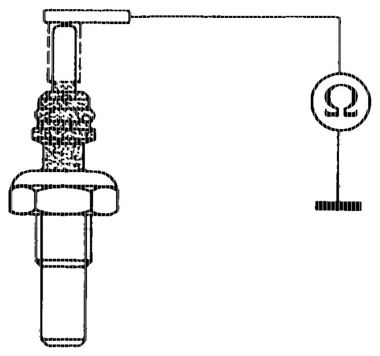
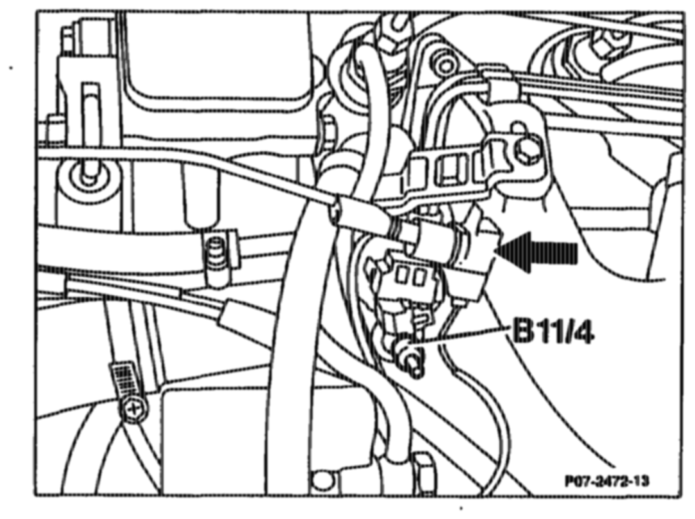
Fault readout 8”
atin = RA 07.1.1042–1120/16
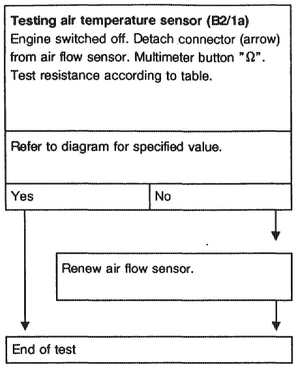
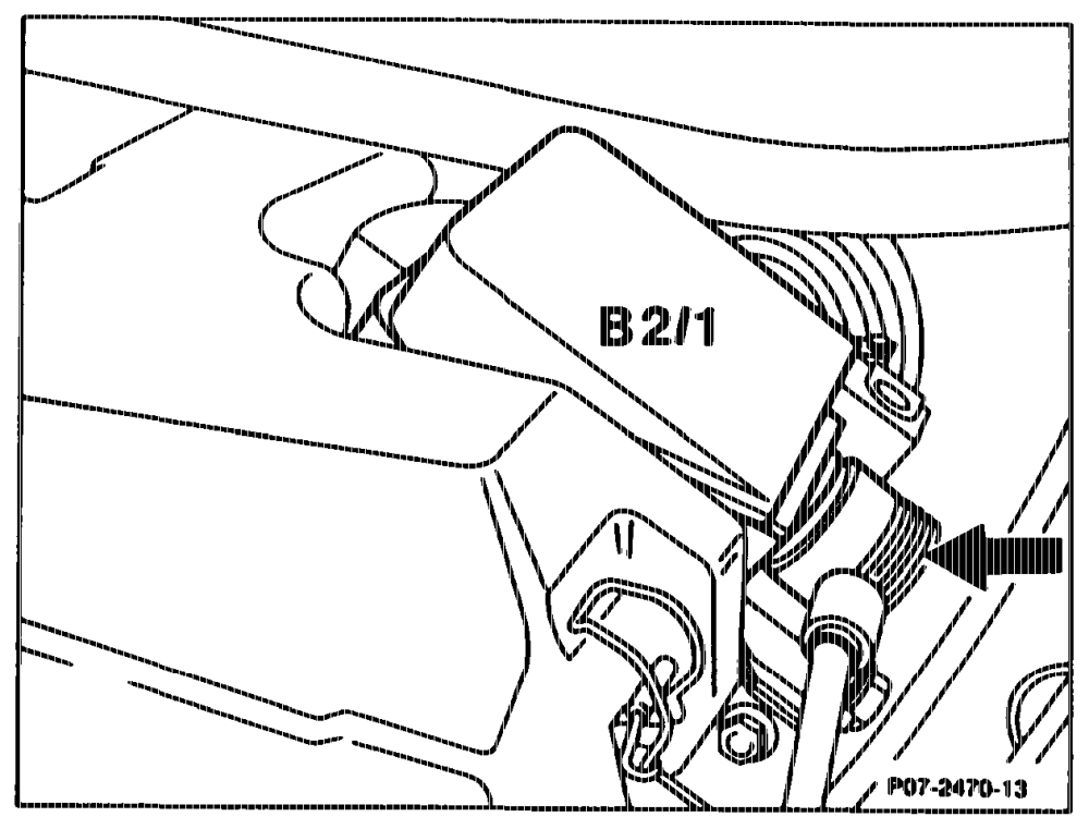
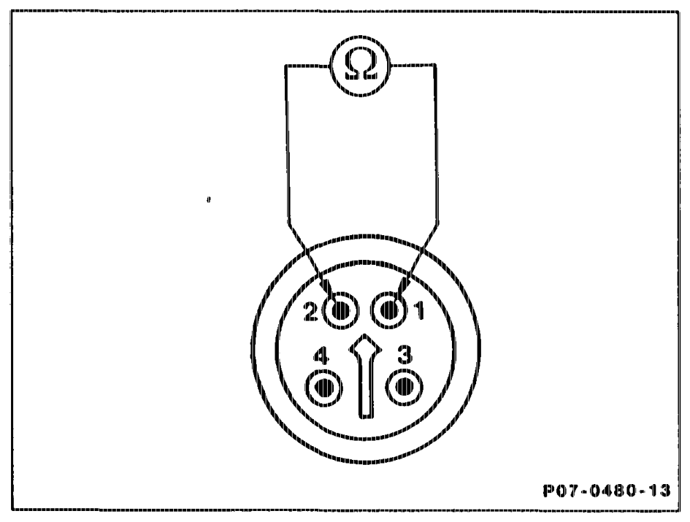
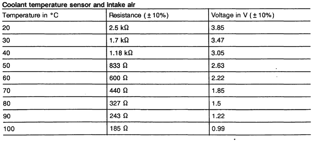
Fault readout ’9”
gts RA 07.1.1042-1120/17
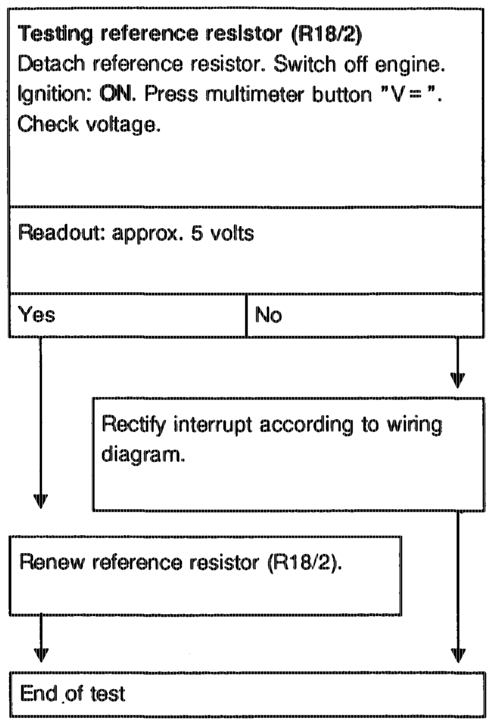
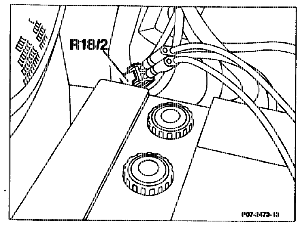
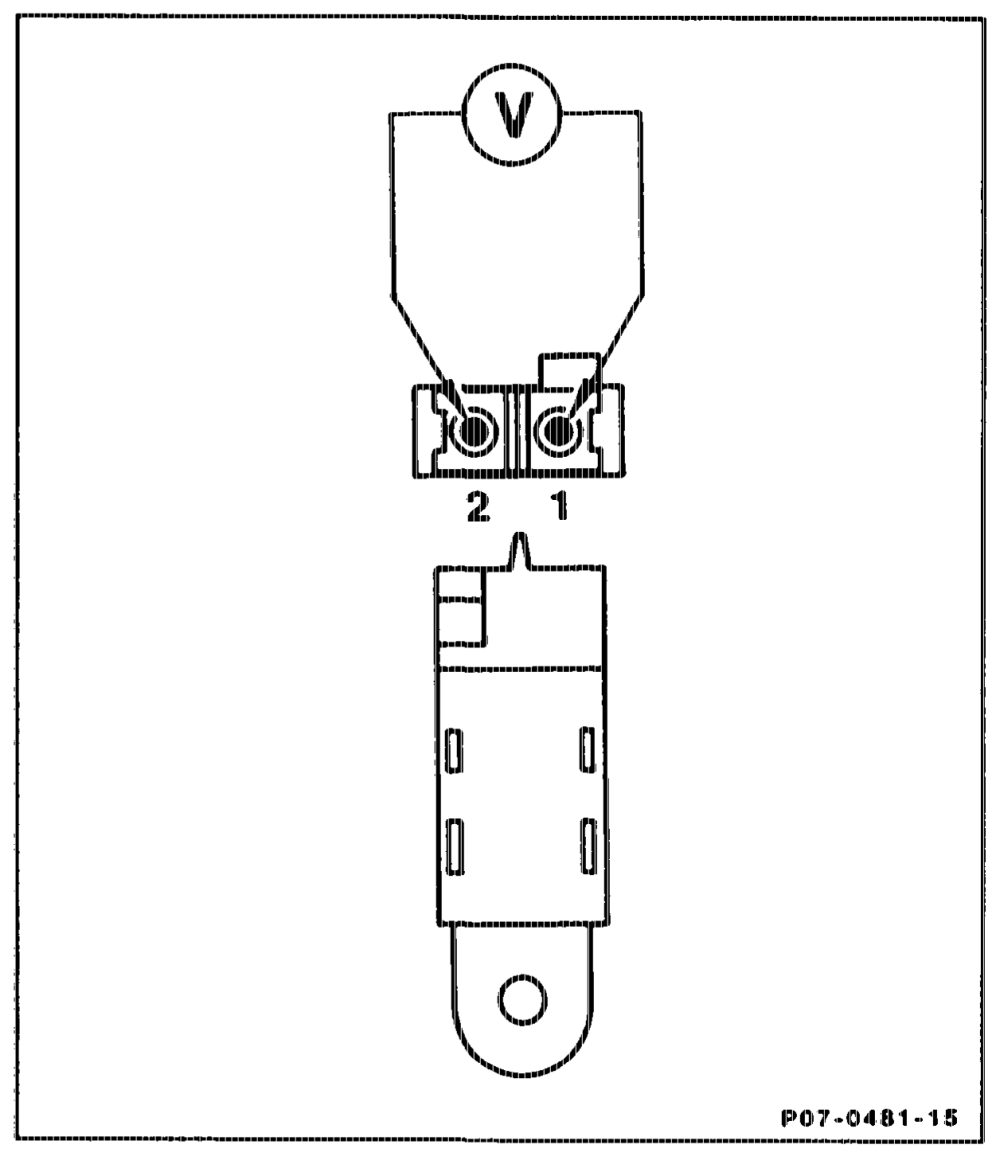
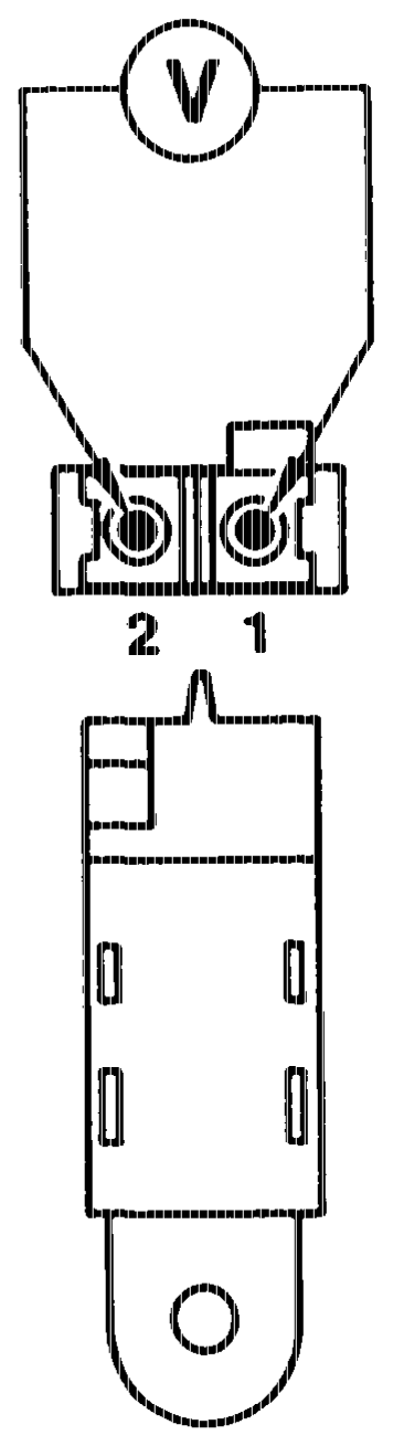
Fault readout ”10”
Note When renewing the reference resistor (R18/2), fit only plug with an identical part no.
aptihiy = RA O7.1.1042-1120/18
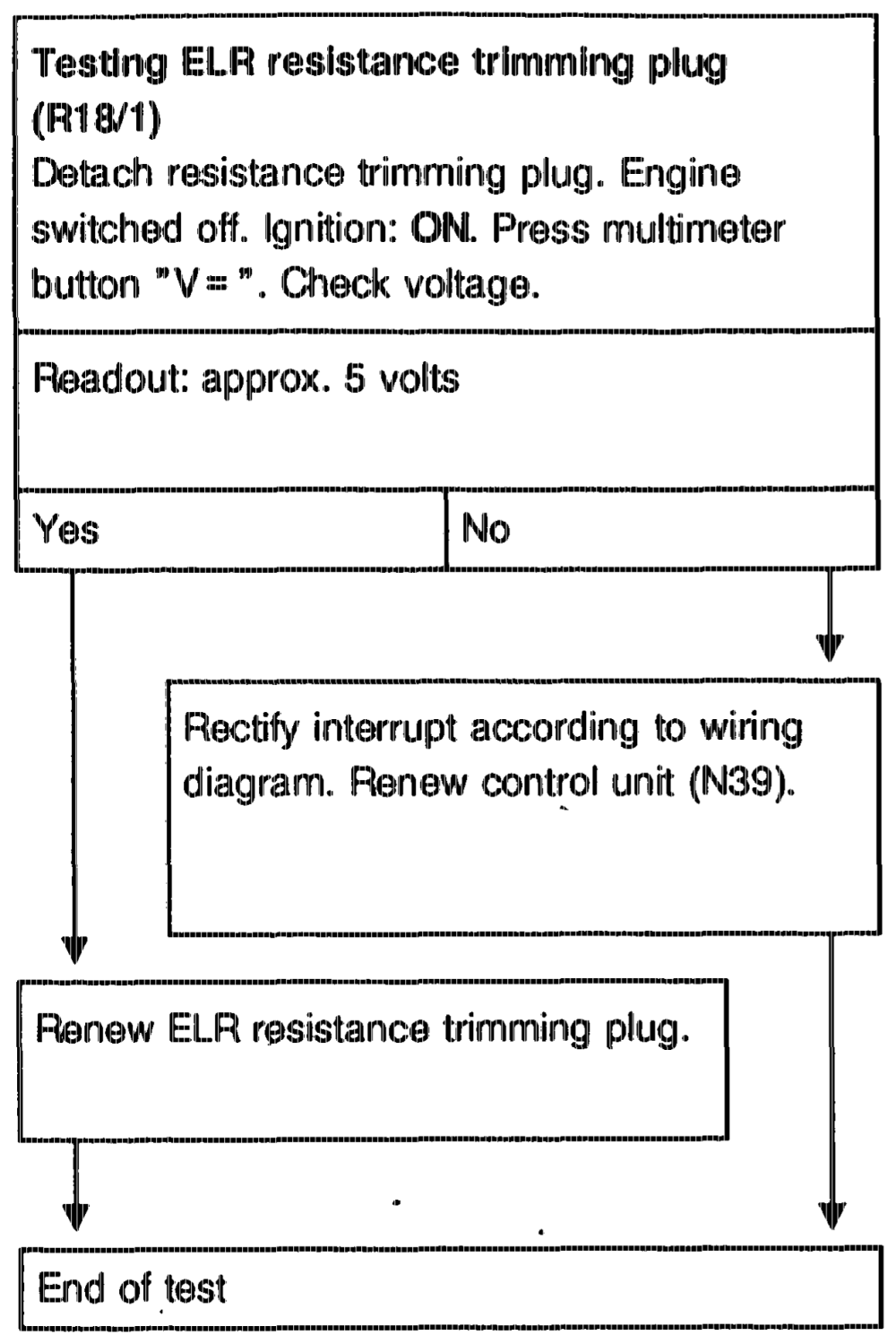
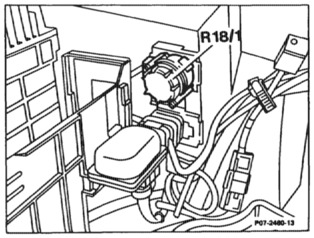
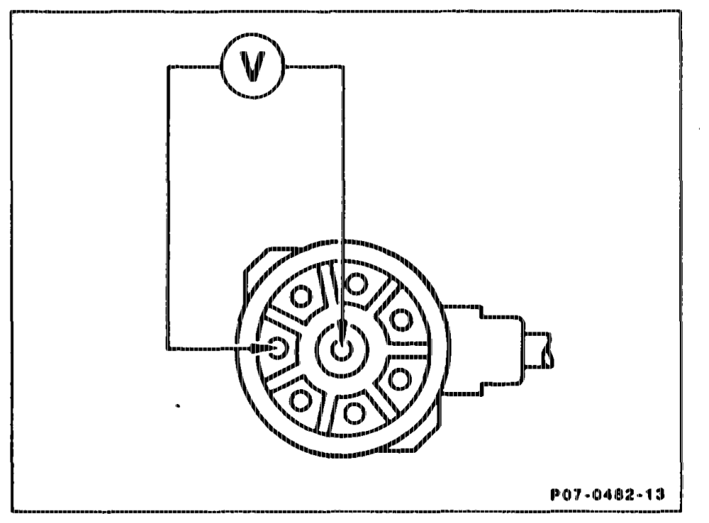
Fault readout ”11”
Note The resistance trimming plug ELR (R18/1) is installed in position „4”.
aptiie = RA O7.1.1042-1120/19 c) Testing electronic idie speed control
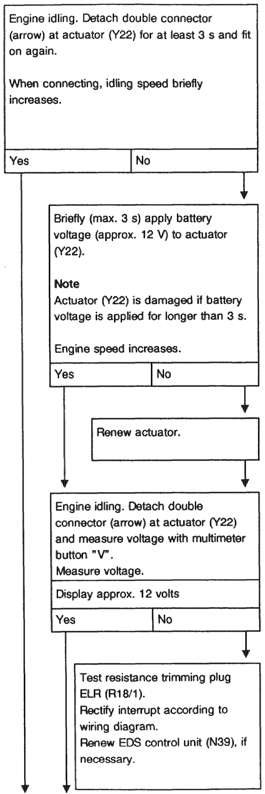
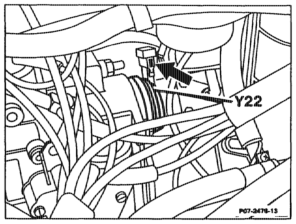
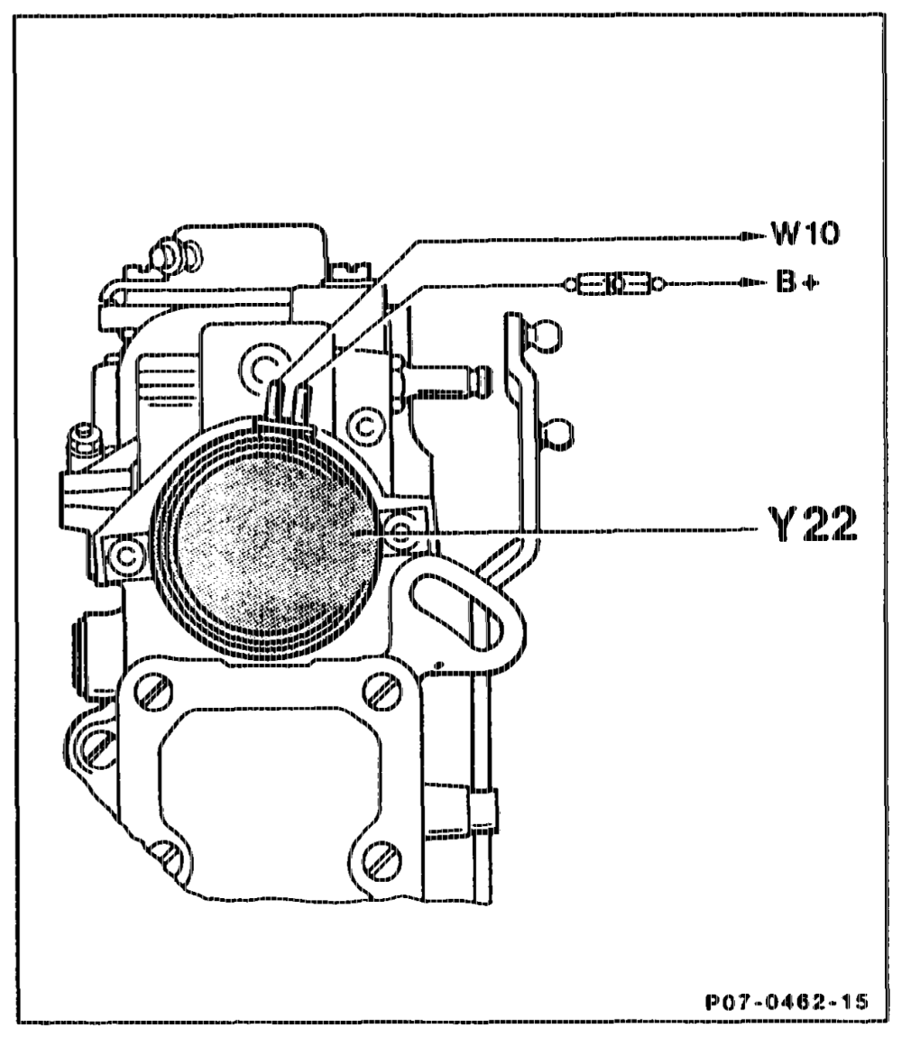
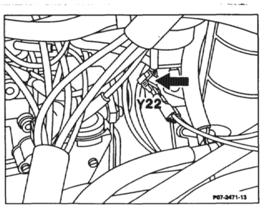
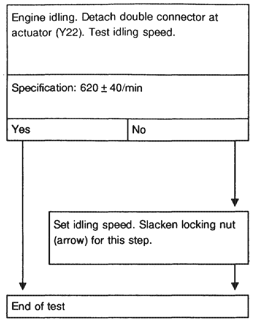
Testing idle speed control
gti = RA 07.1.1042~1120/20
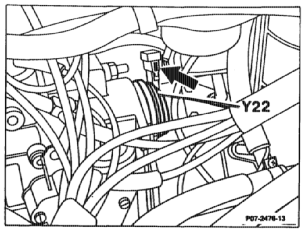
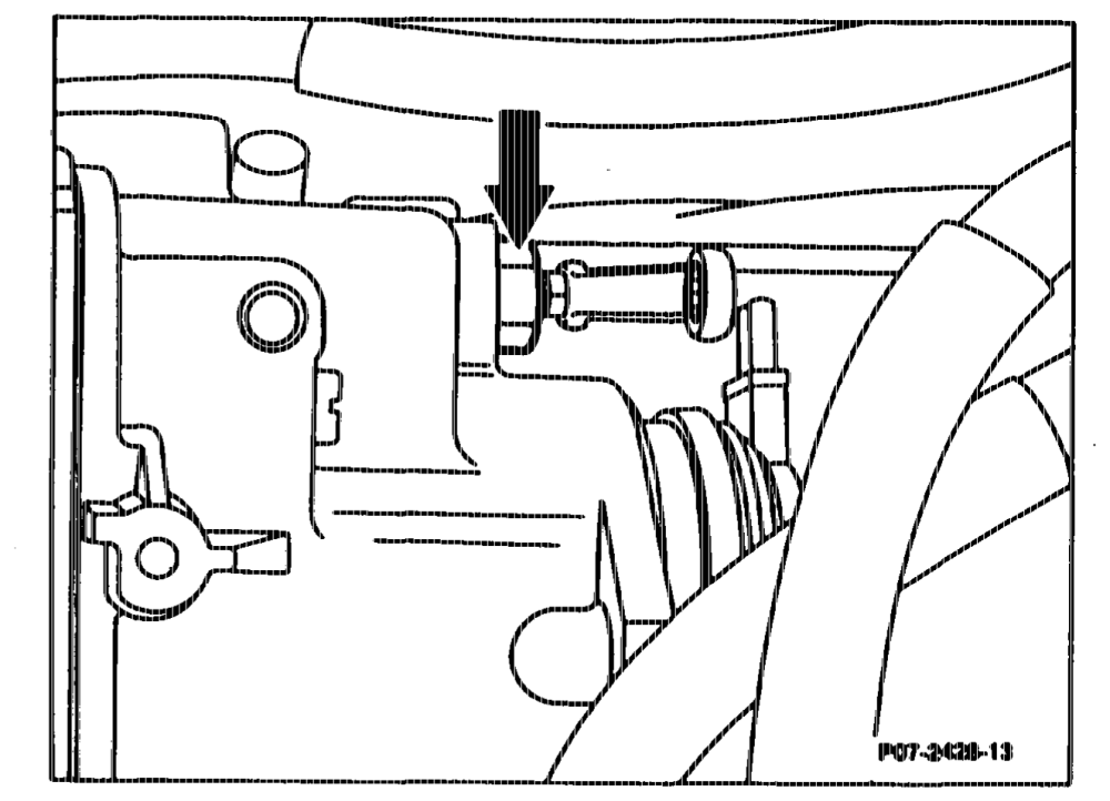
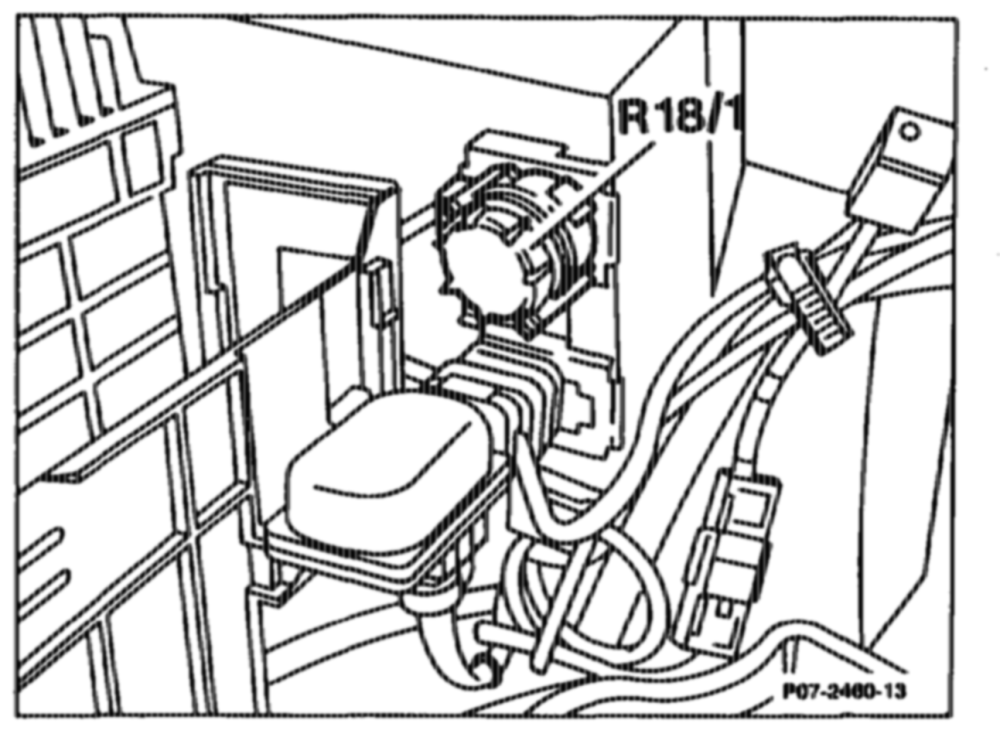
Setting Idling speed by means of resistance trimming plug (R18/1) ff complaints are received regarding idling, idling speed can be altered.
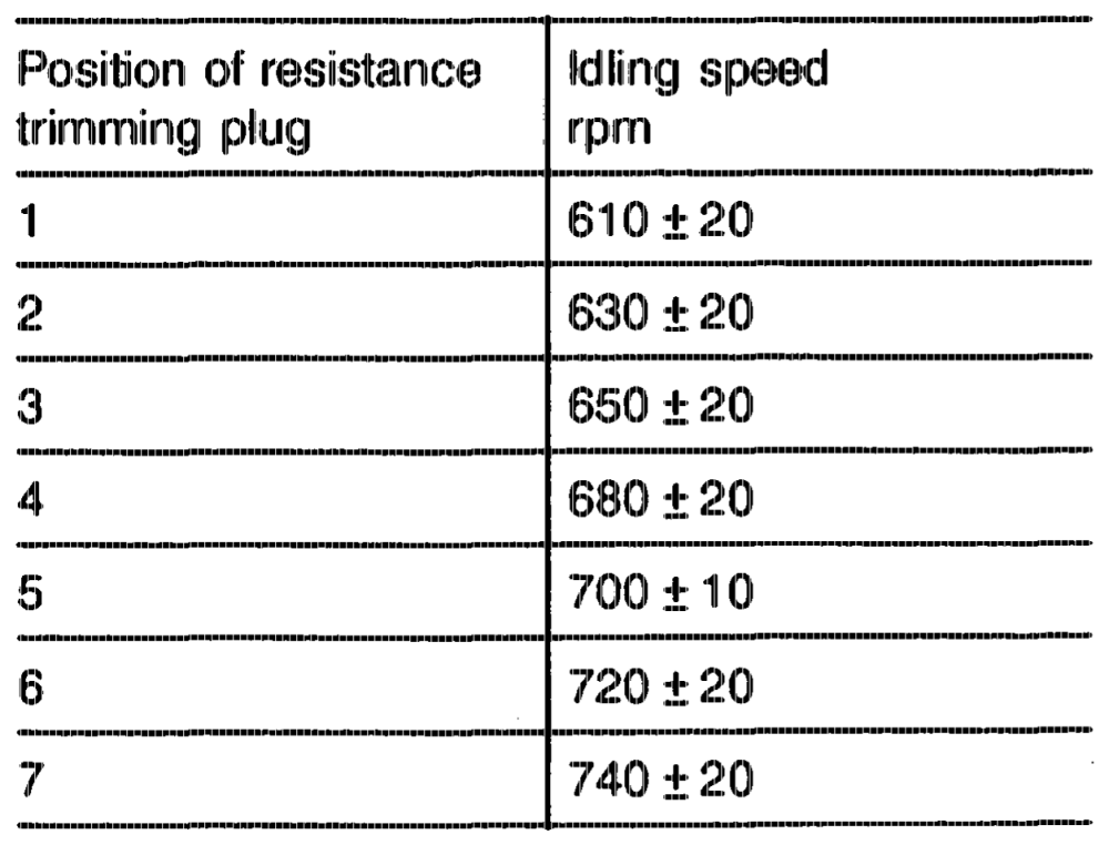
The positions of the resistance trimming plug are listed in the table below.
eptihijy = RA 07.1.1042~1120/21
B. Engine 603.96, Models 124 and 126 Federal and California Model Year 1986/87
a) Short-test b) Testing components c) Testing electronic idle speed control
a) Short-test
gti = RA 07.1.1042-1120/22
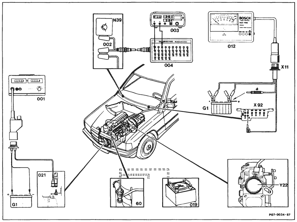
Digital tester (001) and pulse counter (021) ….. connect, disconnect. Lambda control tester (012). 6… eee eee connect, disconnect to battery (G1) and with adaptor to test connector (X92). Contact box (004) 2.6… 2… eee eee connect, disconnect with test cable (002) to EDS control unit (N39). Vacuum tester (019) 2… 2. ee eee ee eee connect, disconnect with Y distributor at ARF valve. Digital multimeter (003) ee eee ee connect, disconnect to contact box (004). Fuse at overvoltage protection (K1/1) ……… test. Selector lever… cee eee eee move into position „P”. switch off. Air conditioning/automatic climate control …… bring to operating temperature EMQine 2… cee eee eee ee eee (Coolant temperature approx. 80 °C)
Note When performing the test work, the air intake hose between the air flow sensor and exhaust gas turbocharger must be fitted, otherwise no signal will pass frorn the air flow sensor to the control unit (N39). Connector „a” we eee ee eee hold approx. 1 second to battery ground; 100 % readout. Connector „a oe eee take off; 0 % readout, no fault in system. Readout fluctuates, fault in system (refer to troubleshooting table).
Note One pulse = 0% -— 100 % -0 %
The number of pulses indicates which component is defective.
Repeat test step until no further pulses are displayed.
iis = RA 07.1.1042~1120/23
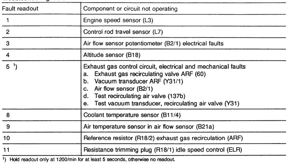
Troubleshooting table
see we eee ween connect, disconnect to ELR actuator Y22 (at Double connector …… least 3 seconds).
Engine speed increases briefly. Engine 2… ee ce eee ene run at approx. 1200 rpm and set approx. 250 mbar vacuum. Briefly apply full throttle. Vacuum drops to 0 mbar. Engine switched off, pressurize ARF valve ….. with approx. 300 mbar vacuum and pull off further.
AFF valve is heard to close.
aptie = RA 07.1.1042-1120/24 b) Testing components
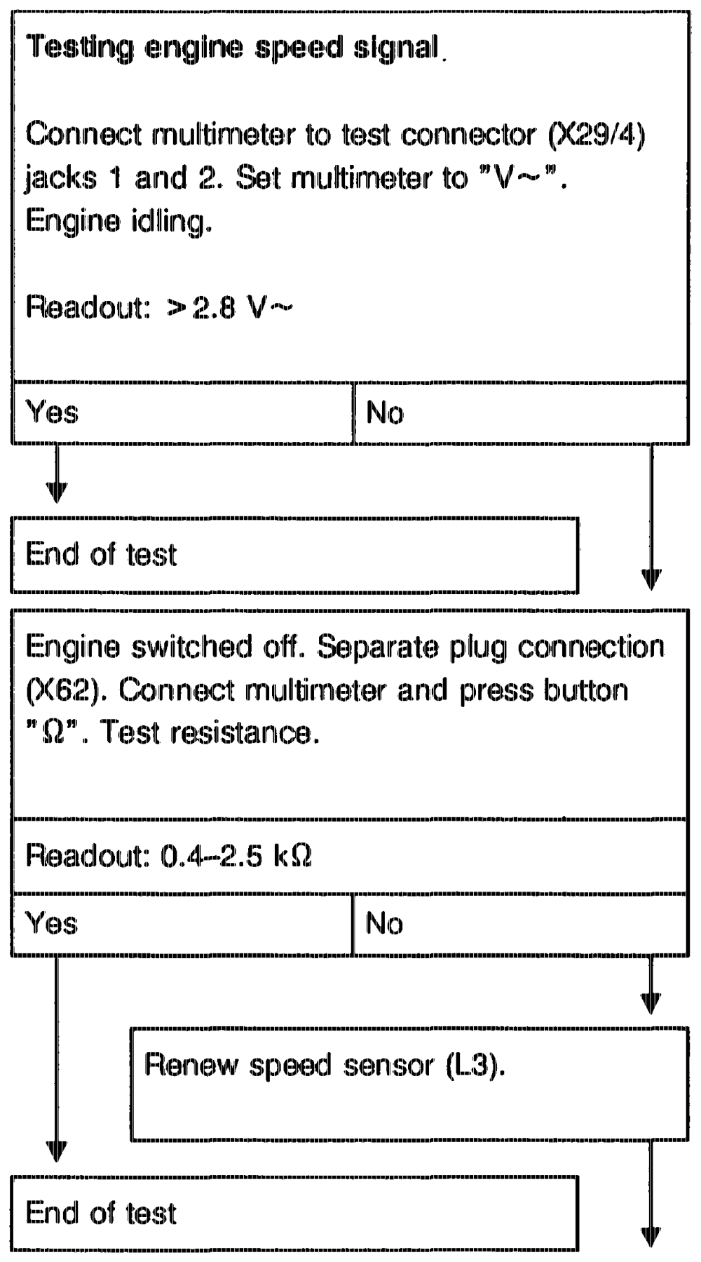
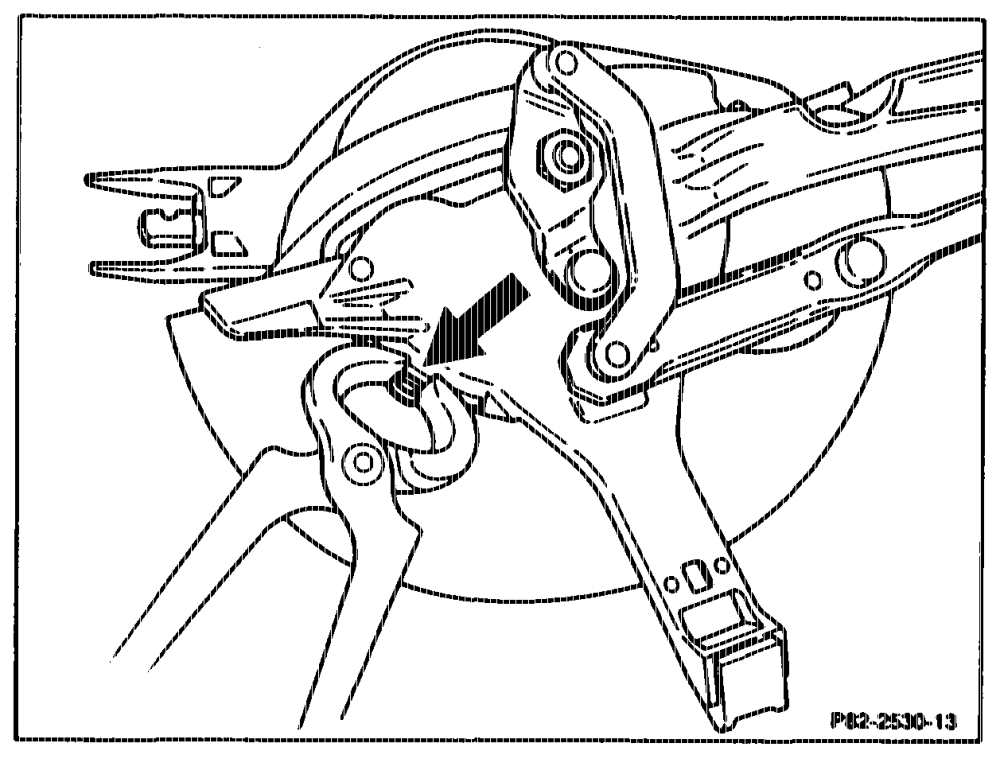
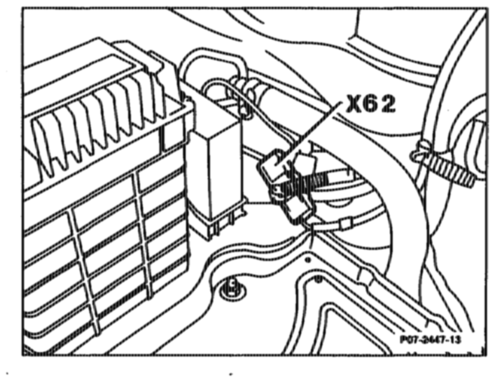
Fault readout „1”
tin RA 07.1.1042~1120/25
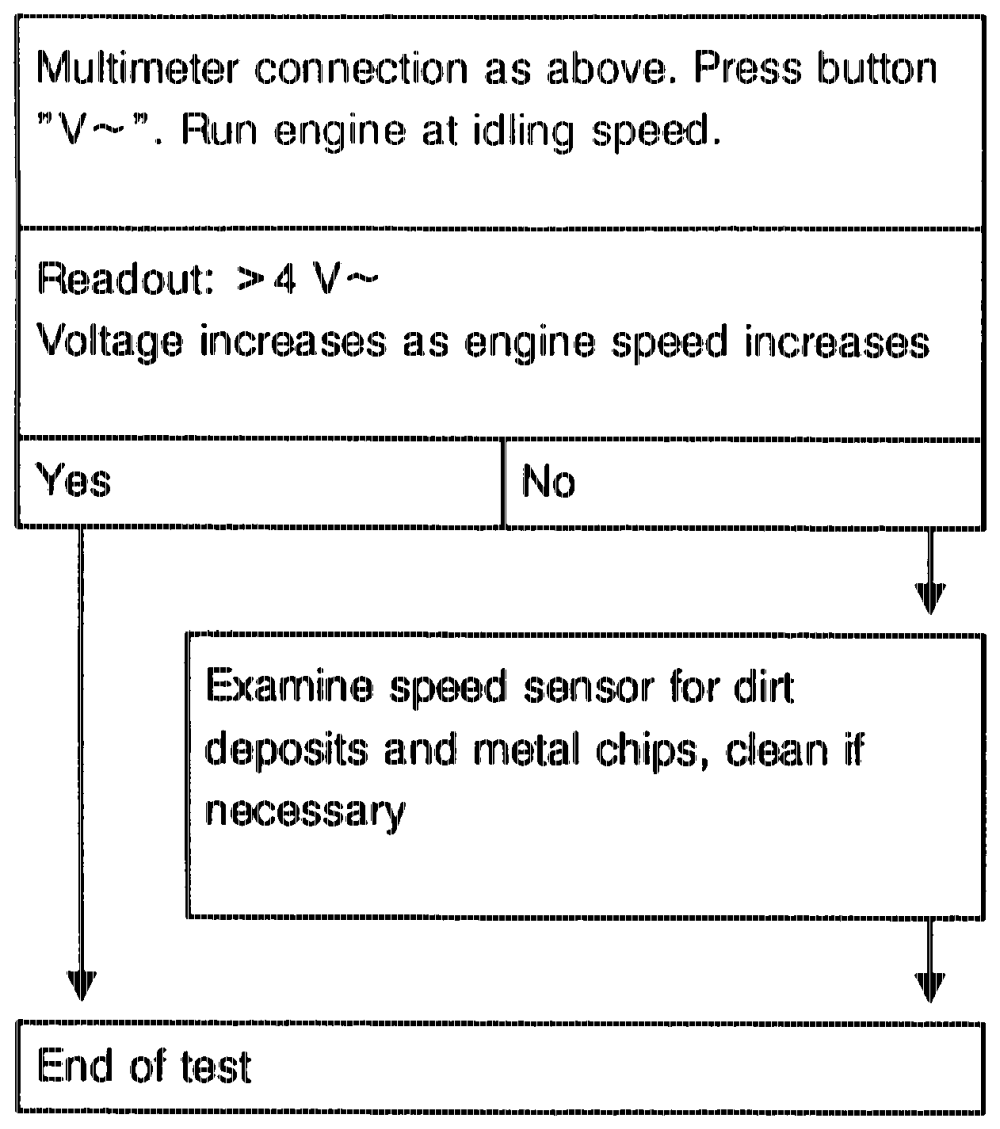
apie RA 07.1.1042–11 20/26
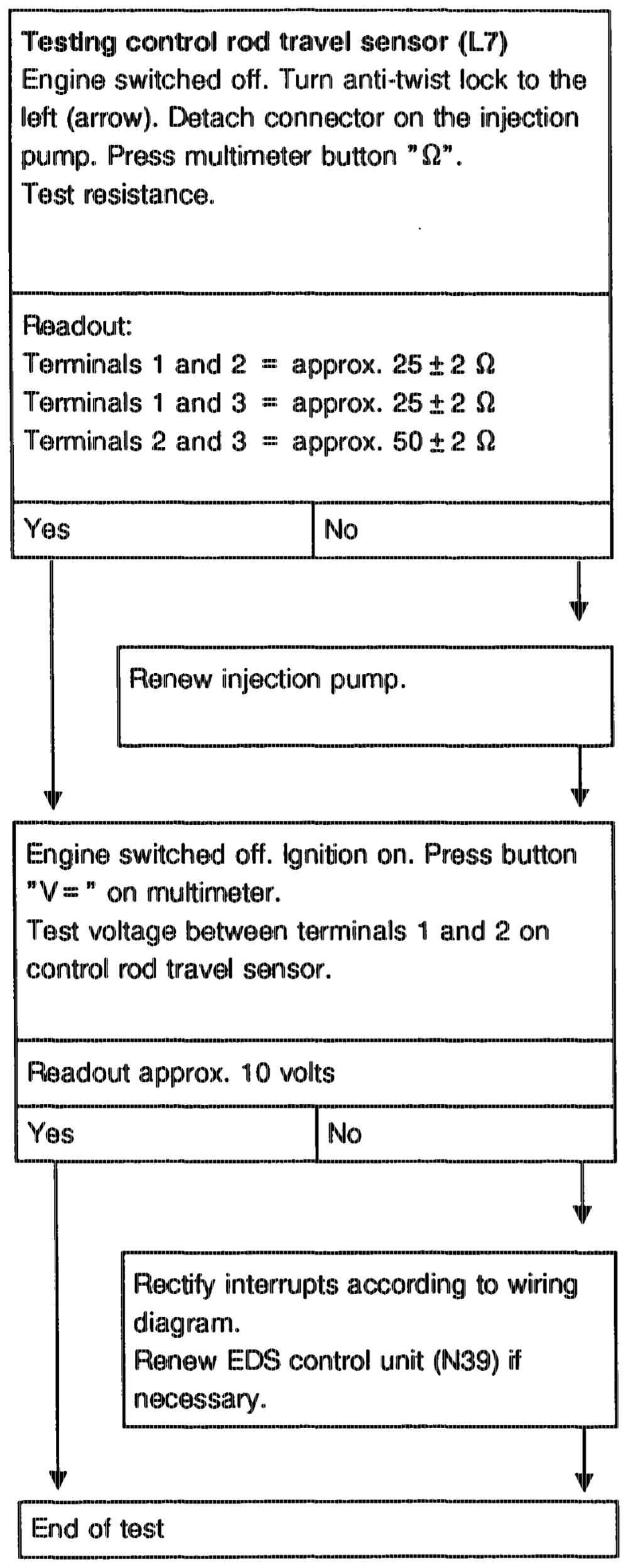
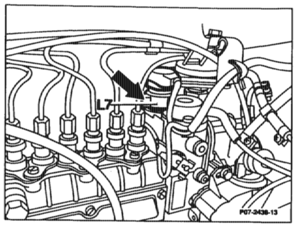
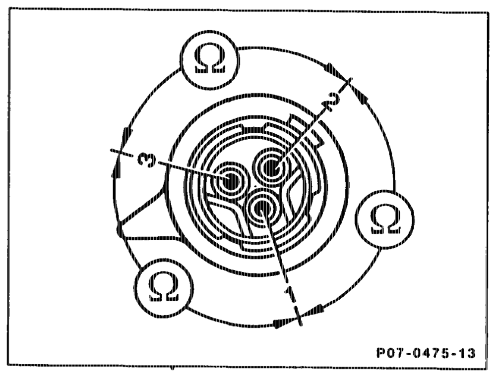
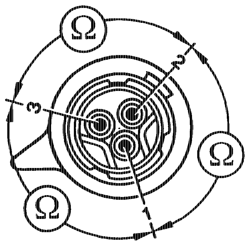
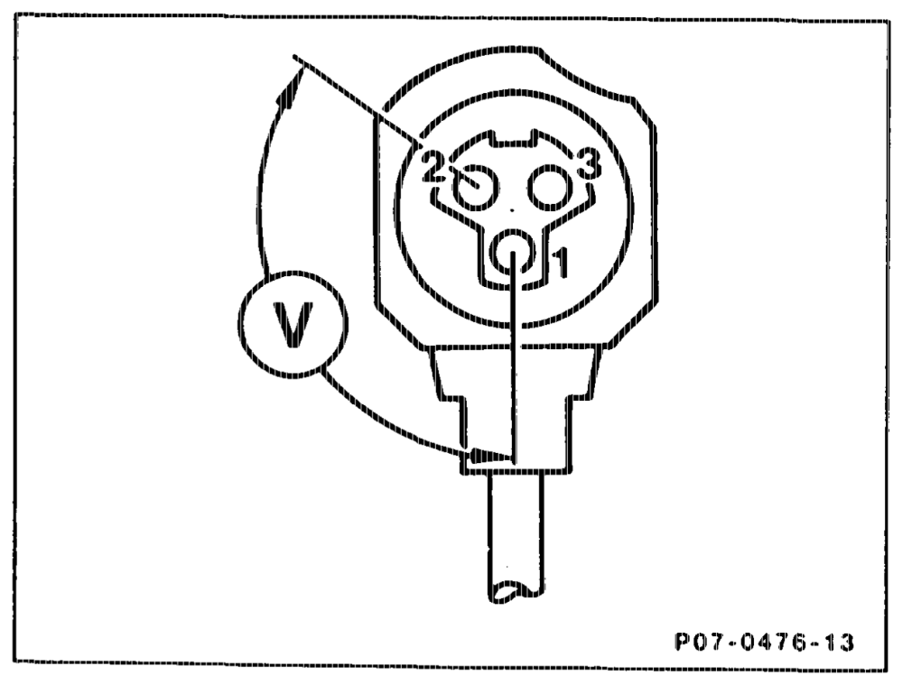
Fault readout ”2”
Note Renew EDS control unit, if fault readout „2” continues to be displayed.
agtine = RA 07.1.1042-1120/27
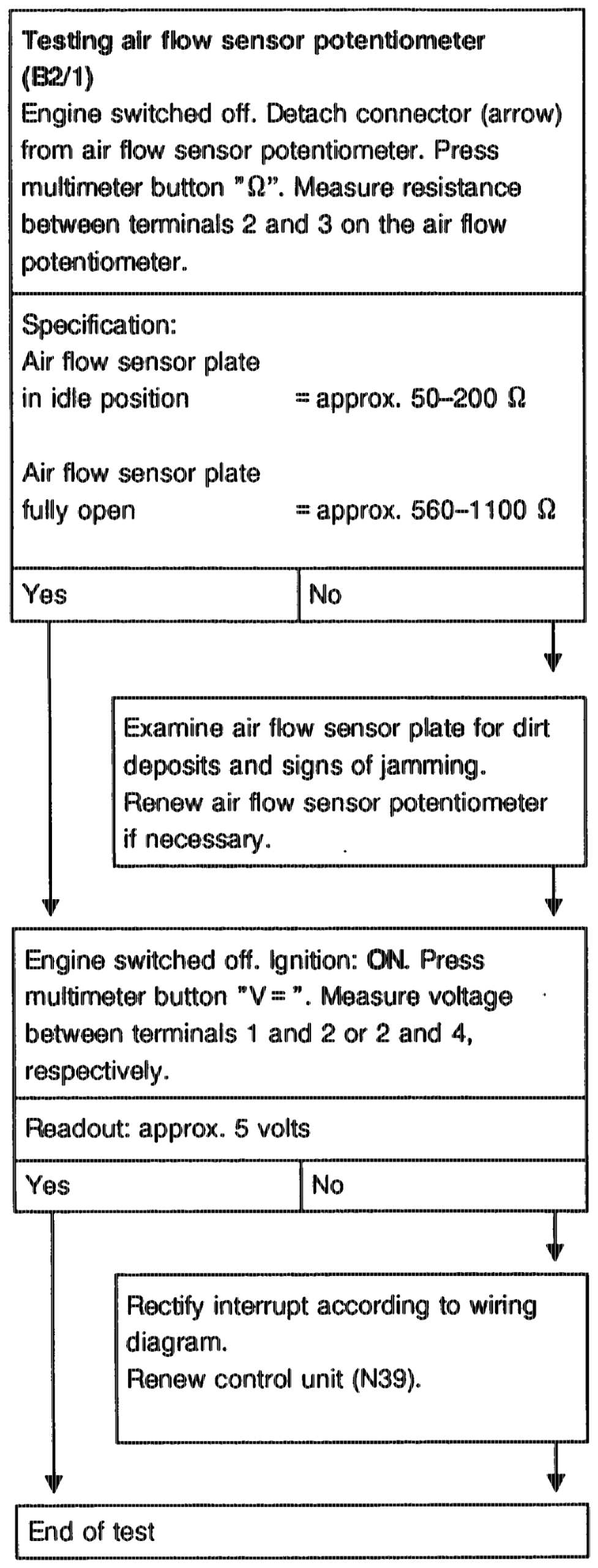
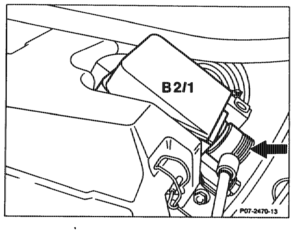
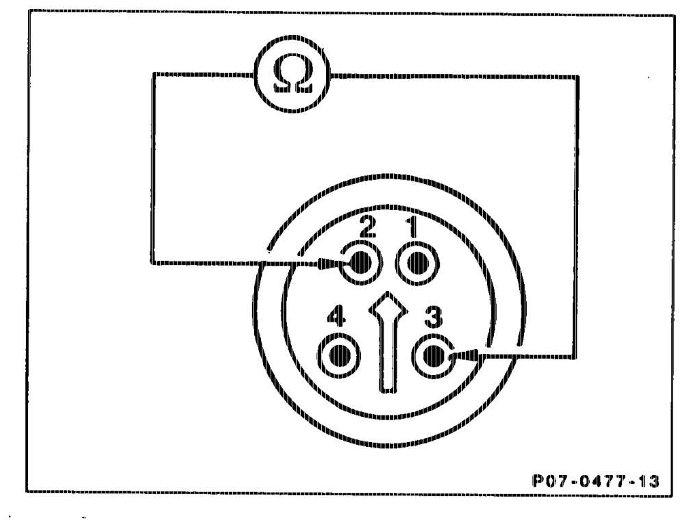
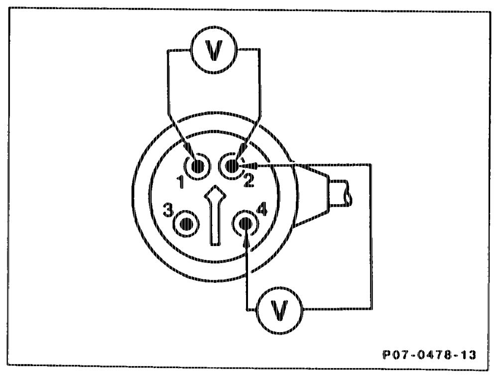
Fault readout „3”
Note If air flow sensor potentiometer has been removed, also perform „Testing air temperature sensor (B2/1a)” (fault readout 9).
eutikiyn = RA 07.1.1042–11 20/28
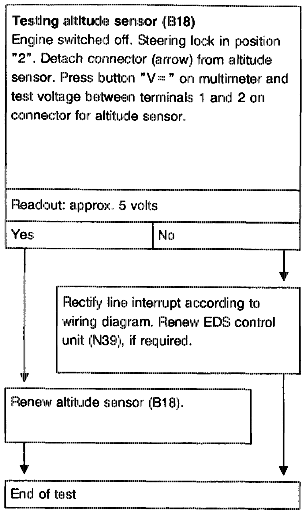
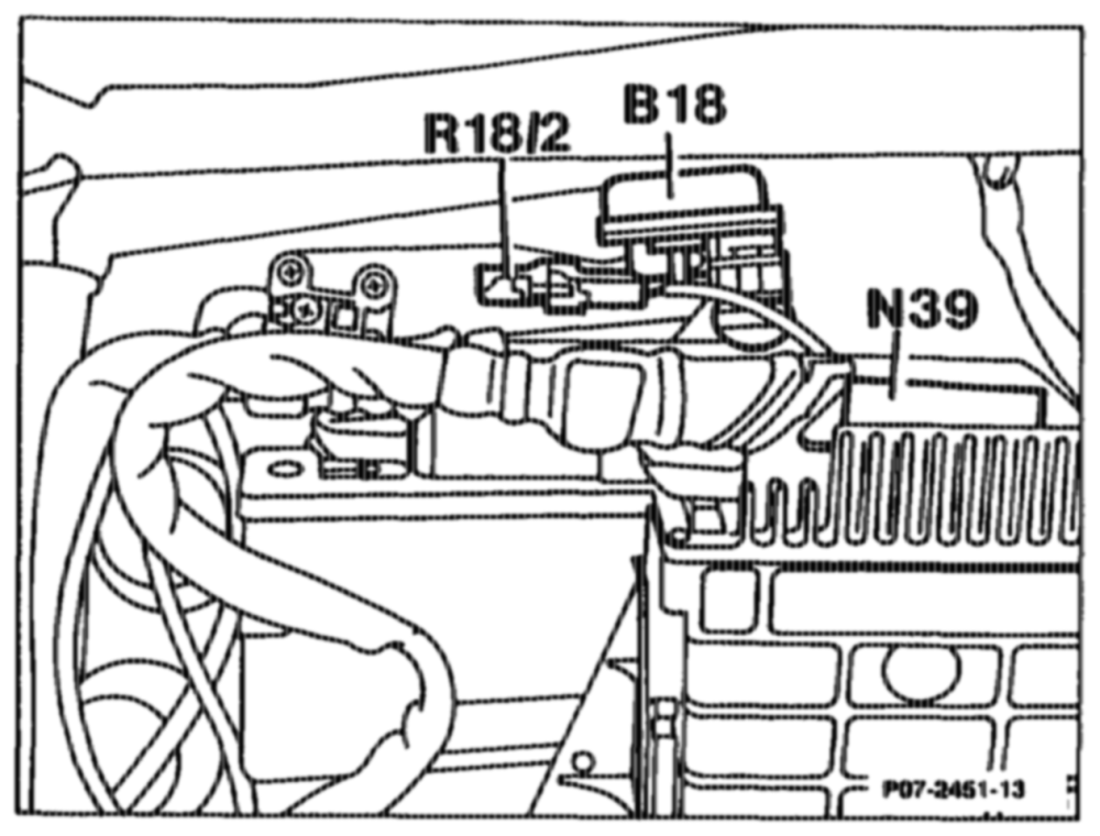
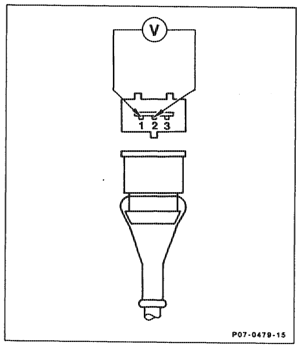
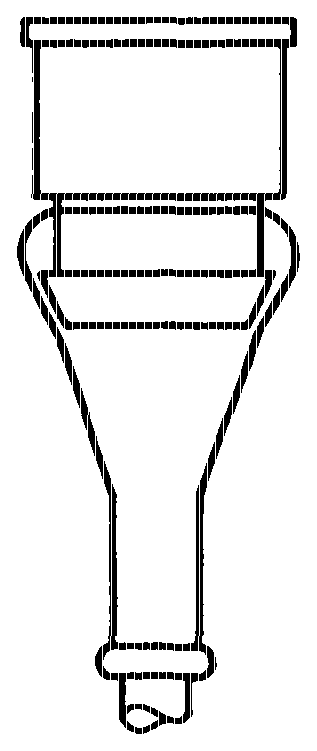
Fault readout „4”
apliim = RA 07.1.1042~1120/29
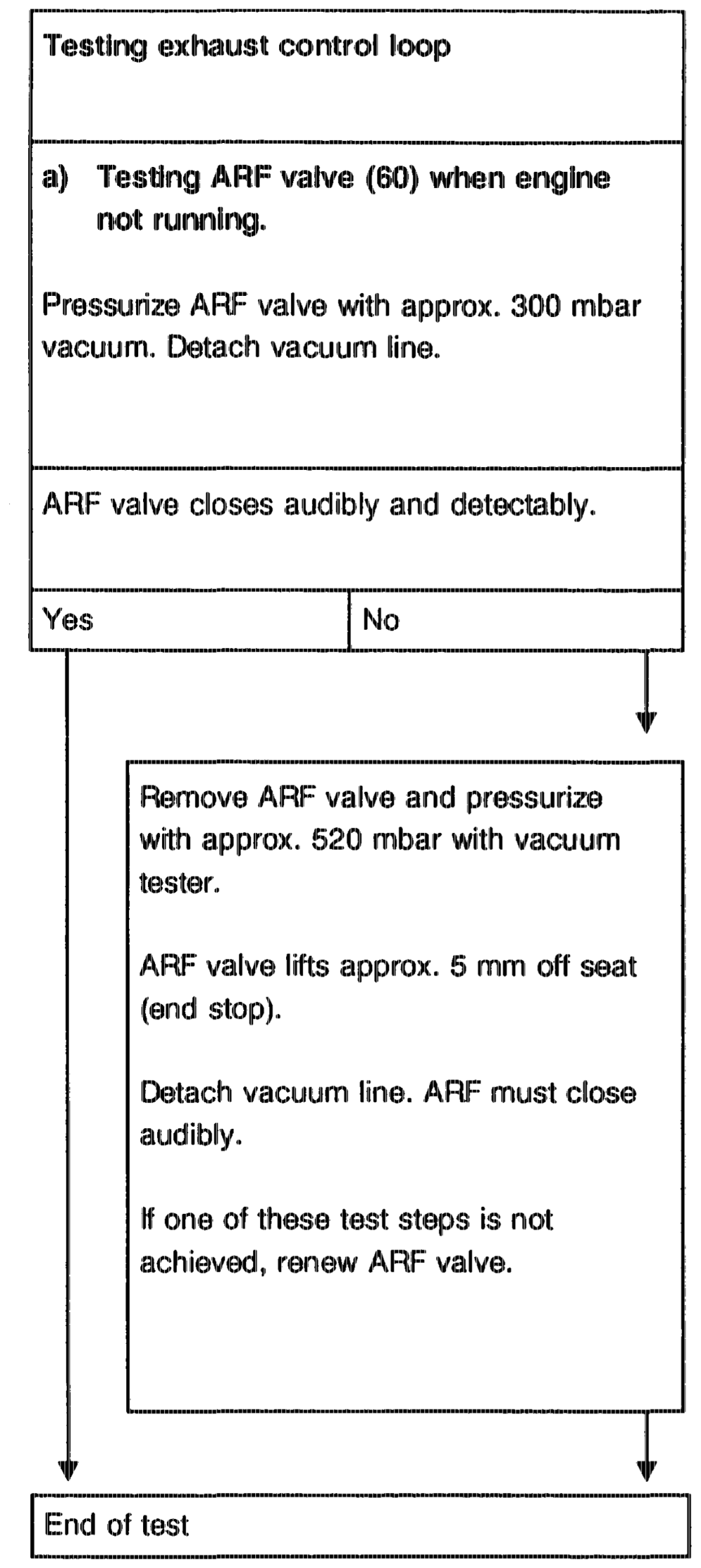
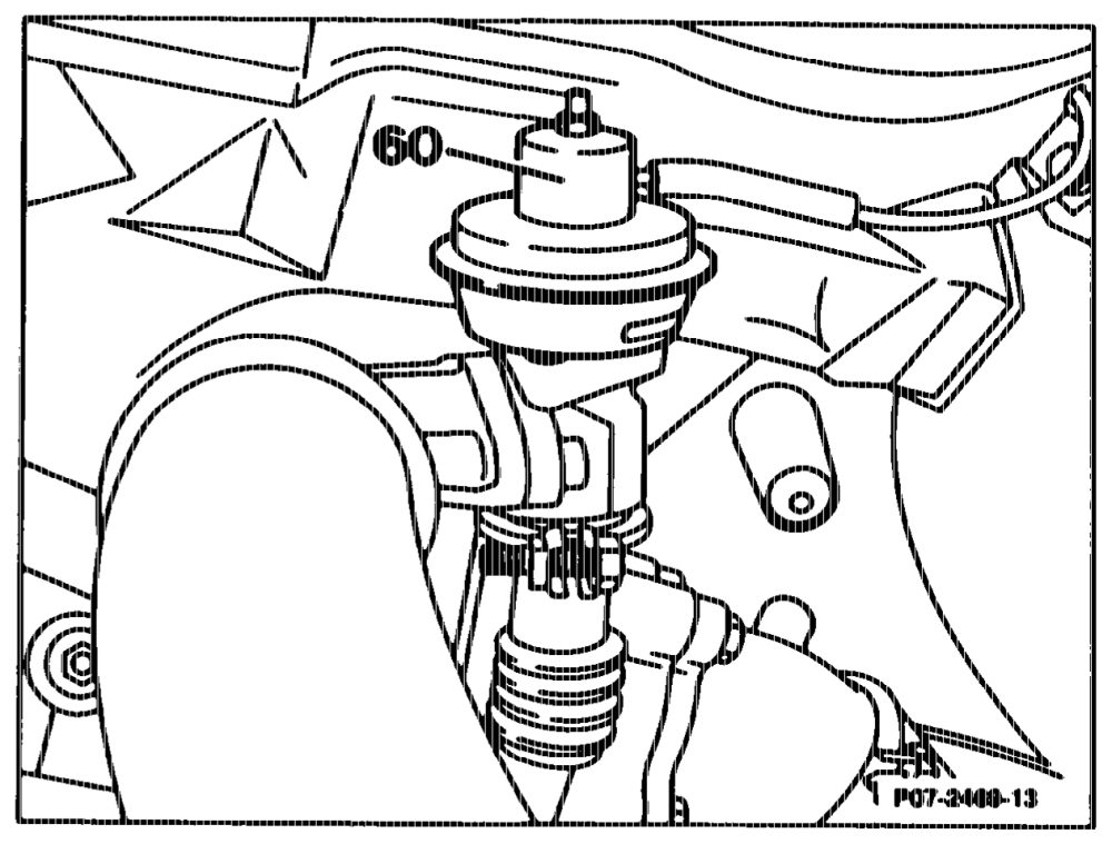
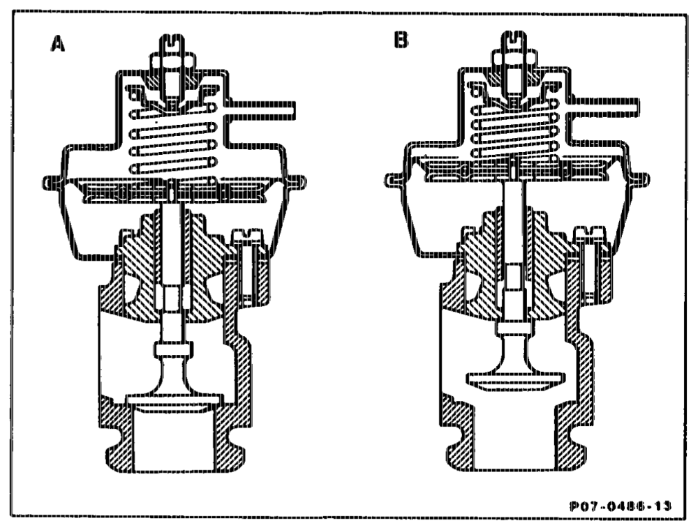
Fault readout ”5”
epthin = RA 07.1.1042-1120/30
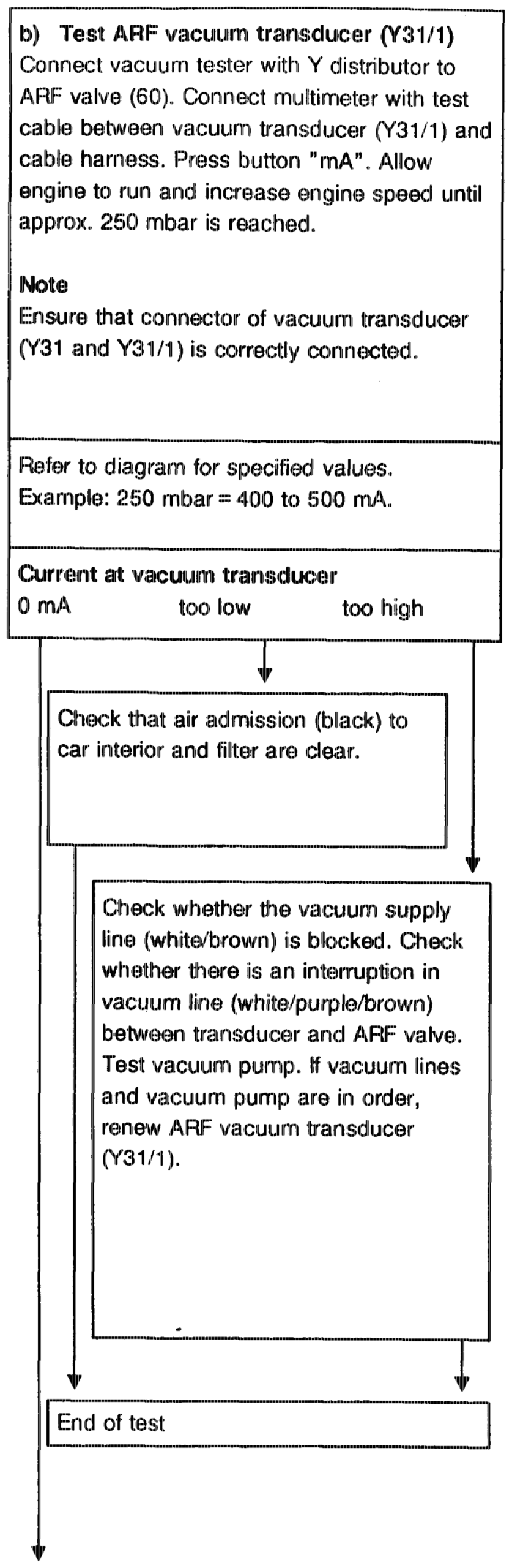
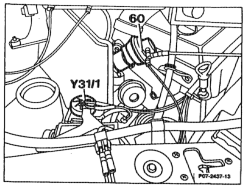
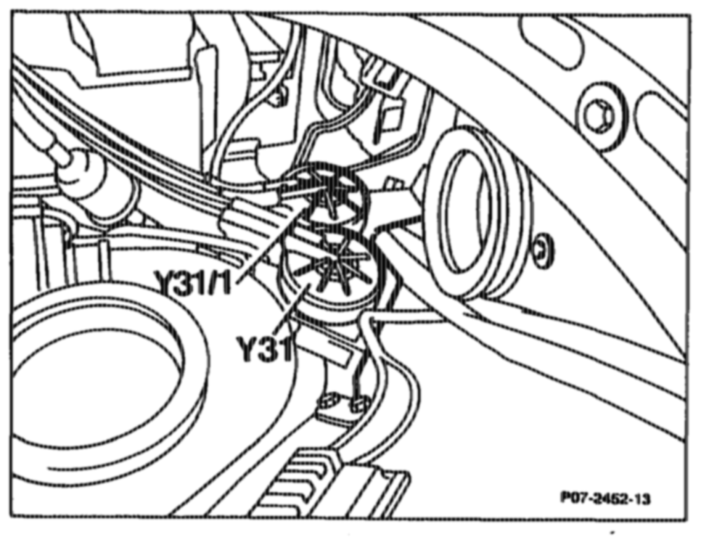
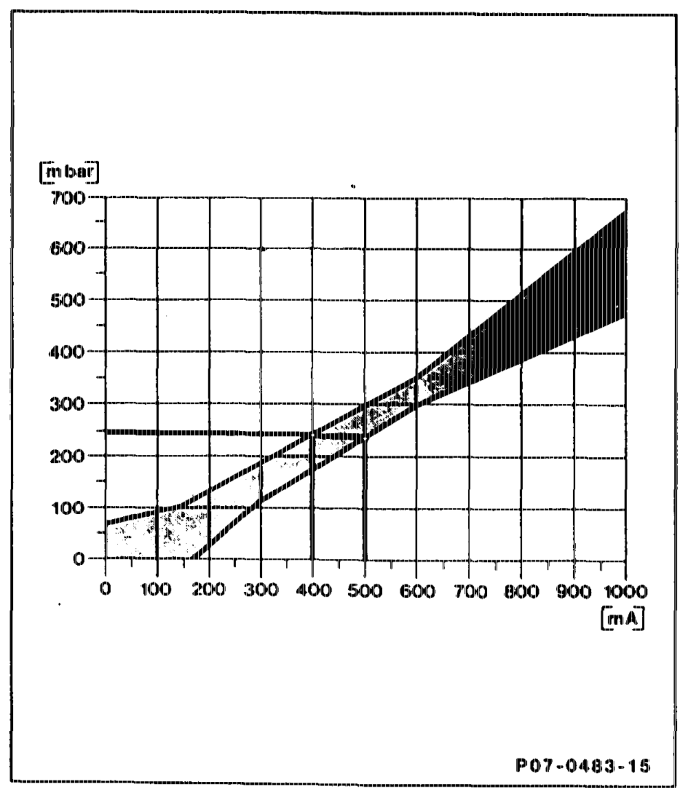
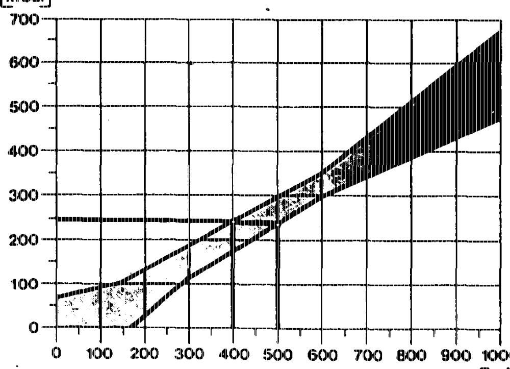
othe AA 07.1.1042-1120/31
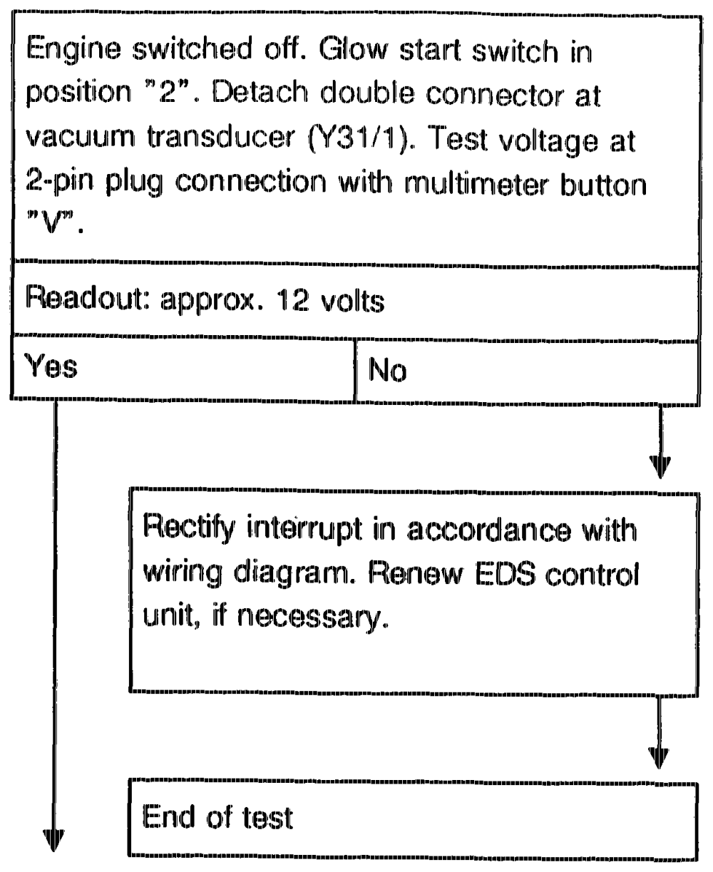
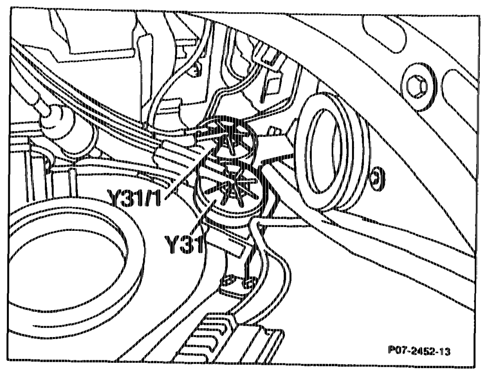
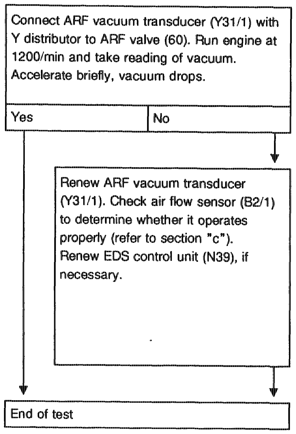
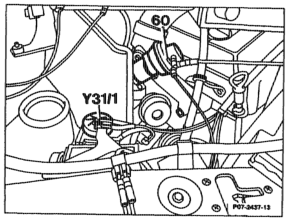
othe — RA 07.1.1042-1120/32
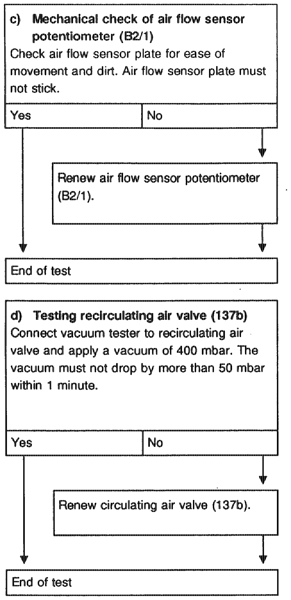
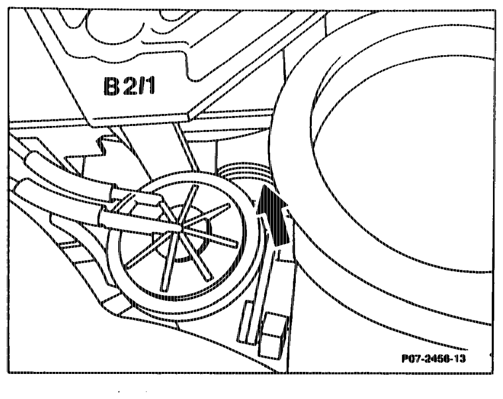
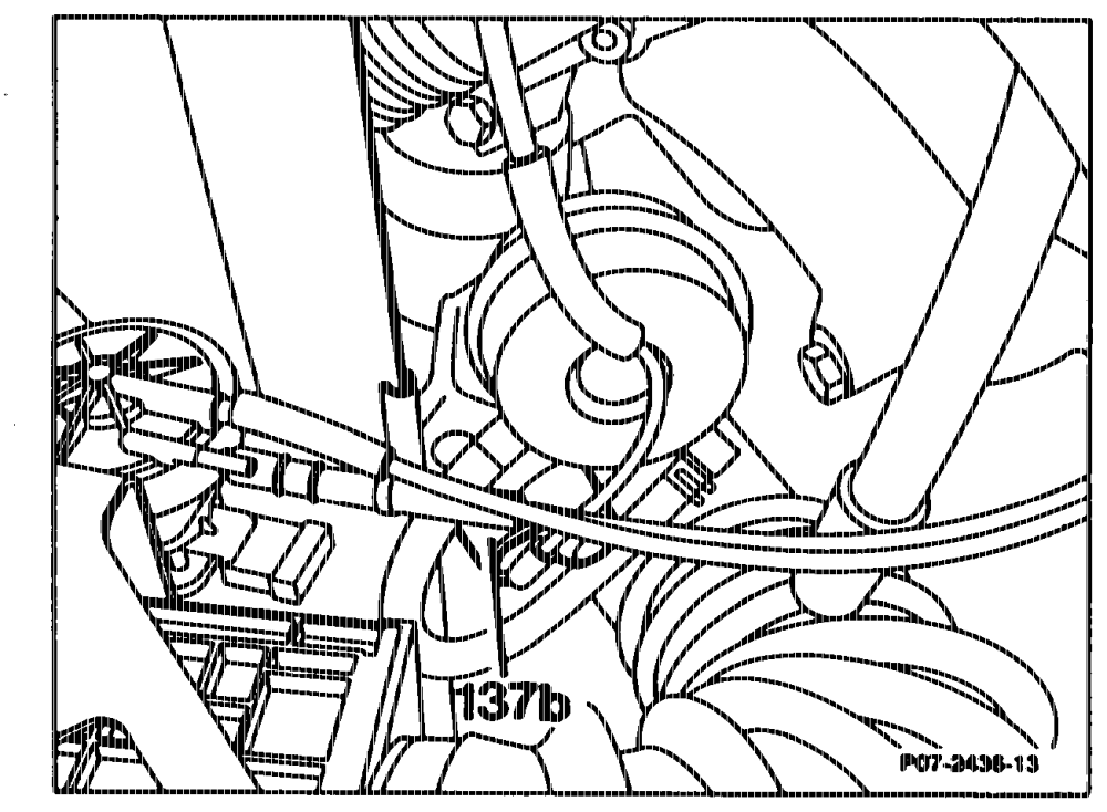
pti RA 07.1.1042-1120/33
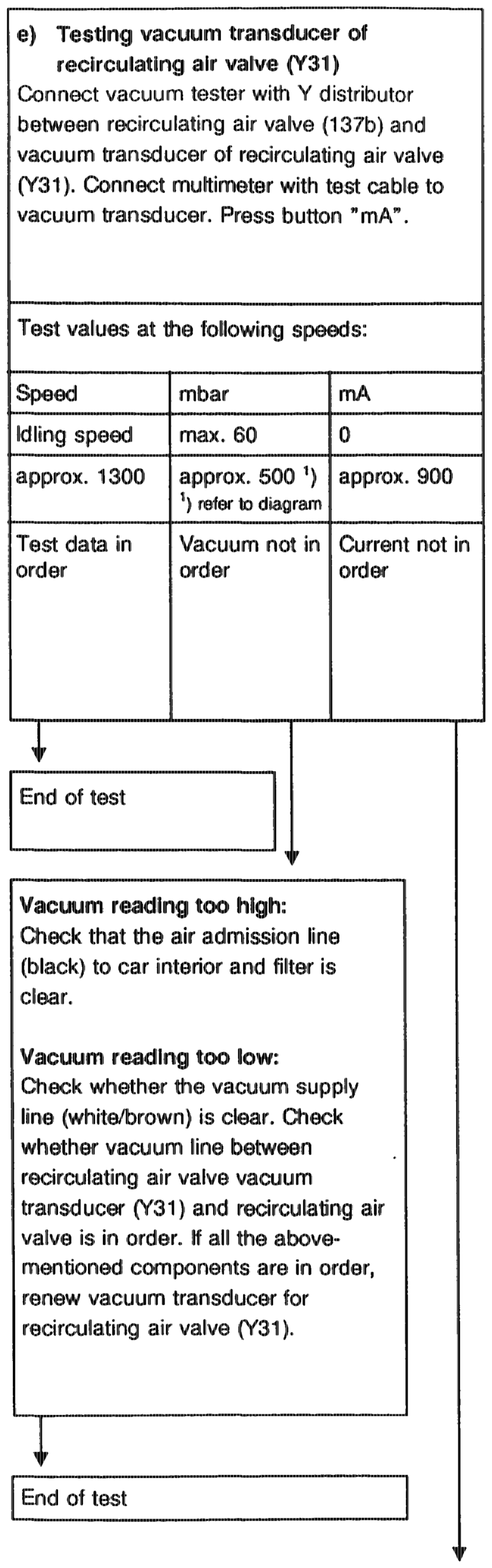
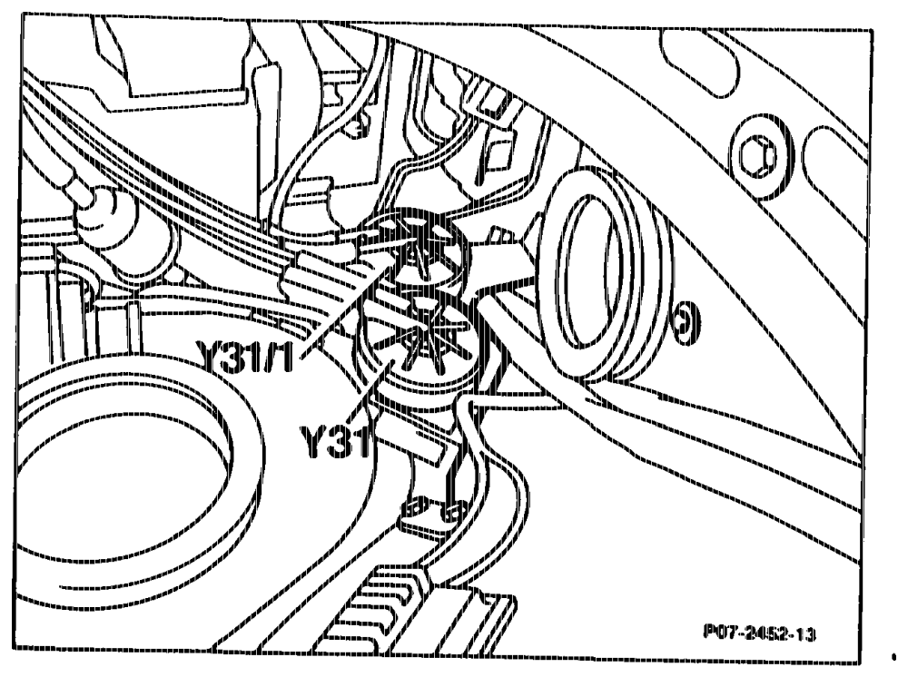
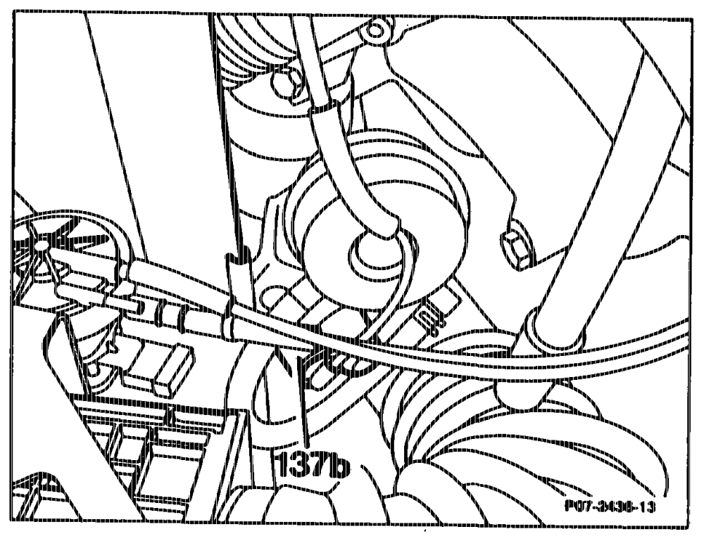
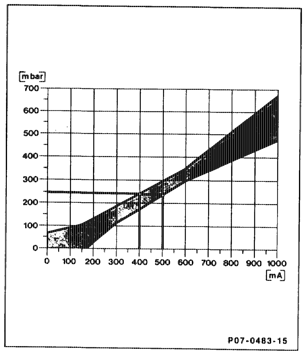
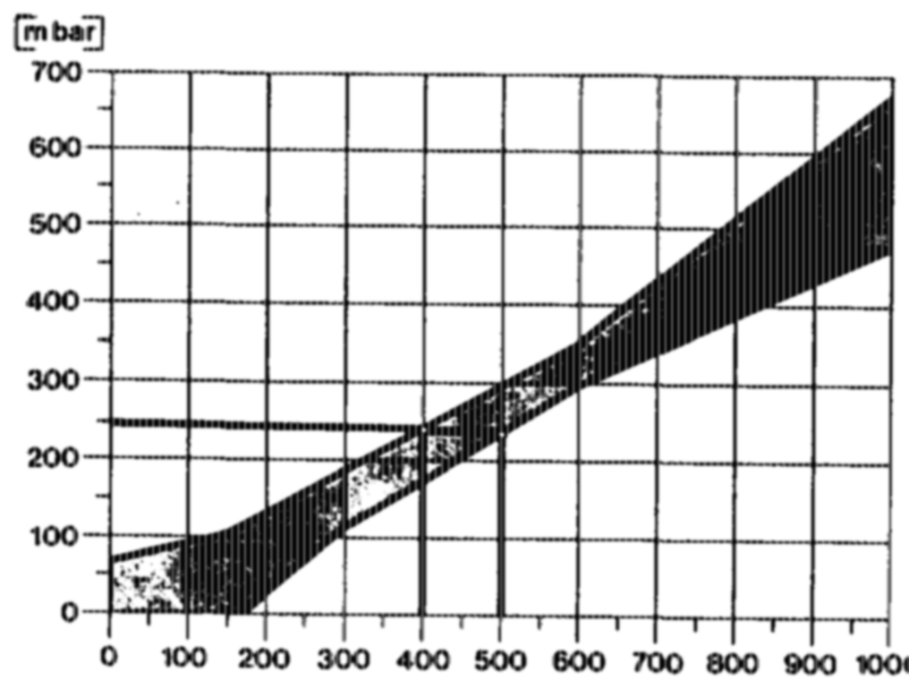
aptiin = RA 07.1.1042~1120/34
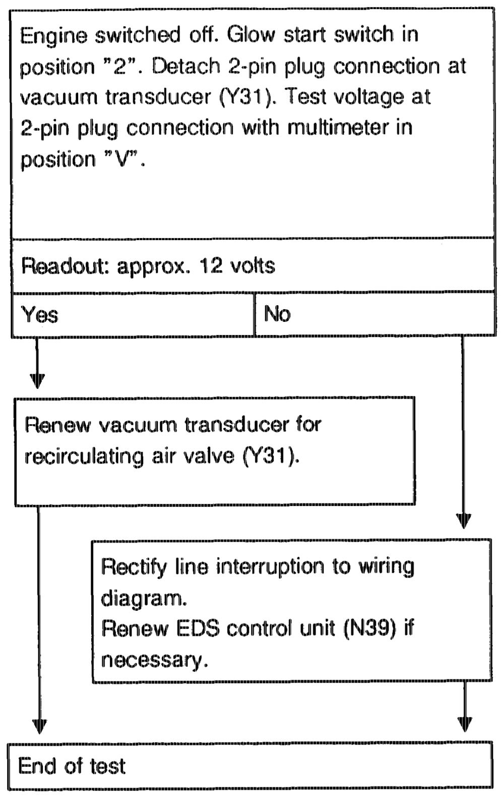
atiiyn = RA 07.1,1042~1120/35
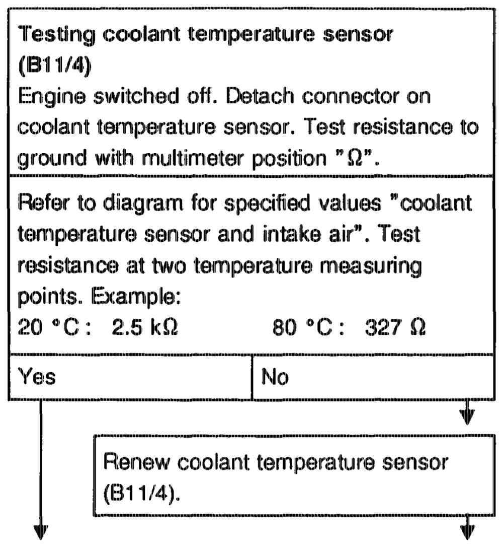
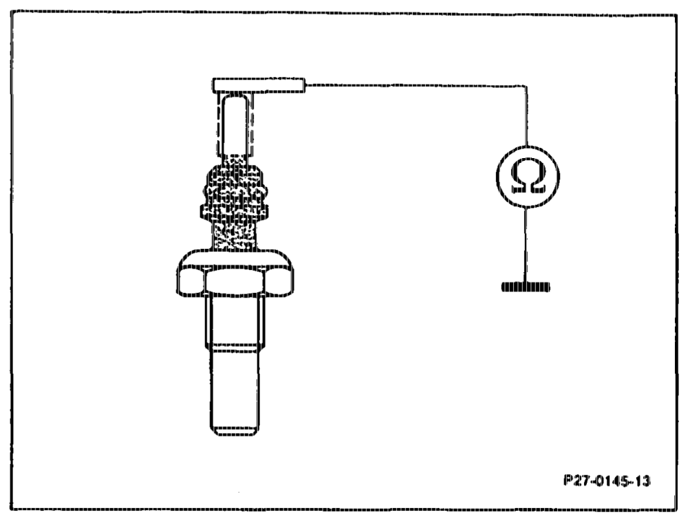
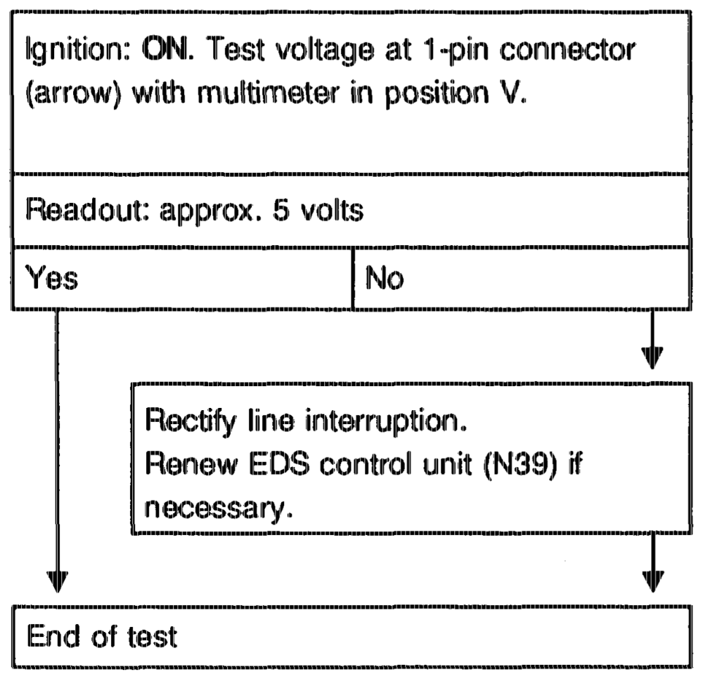
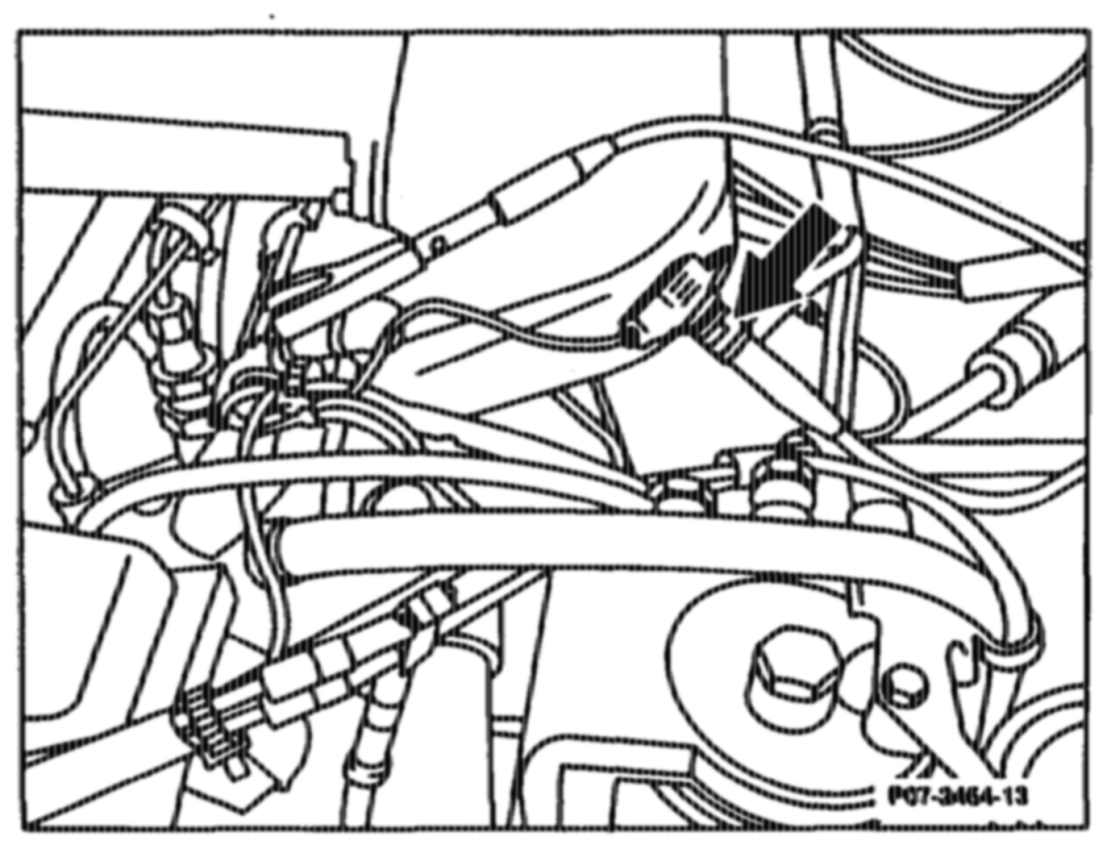
Fault readout „8”
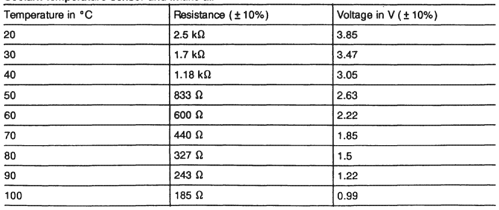
Coolant temperature sensor and intake air
otiiiyn = RA 07.1.1042-1120/36
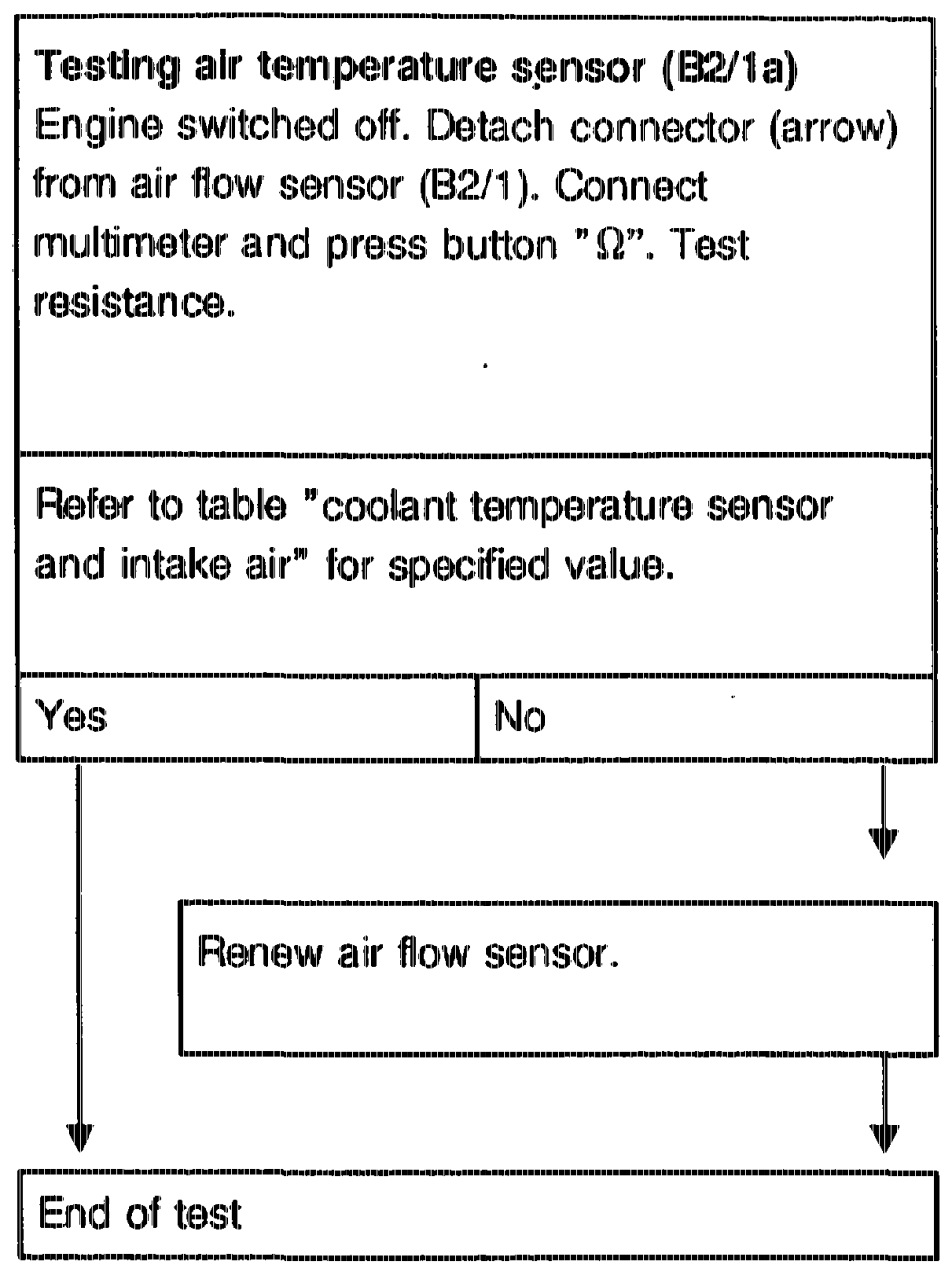
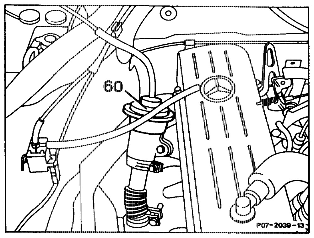
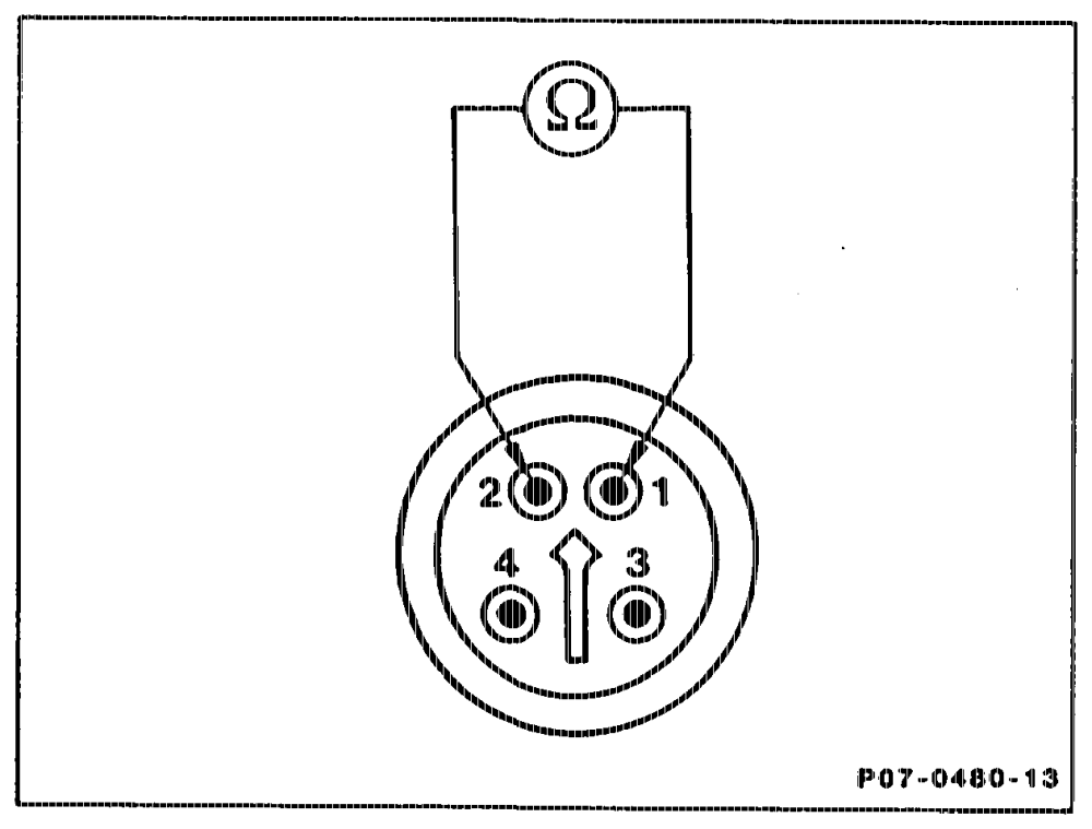
Fault readout ”9”
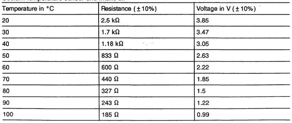
Coolant te erature sensor and intake air
tiie RA 07.1.1042-1120/37
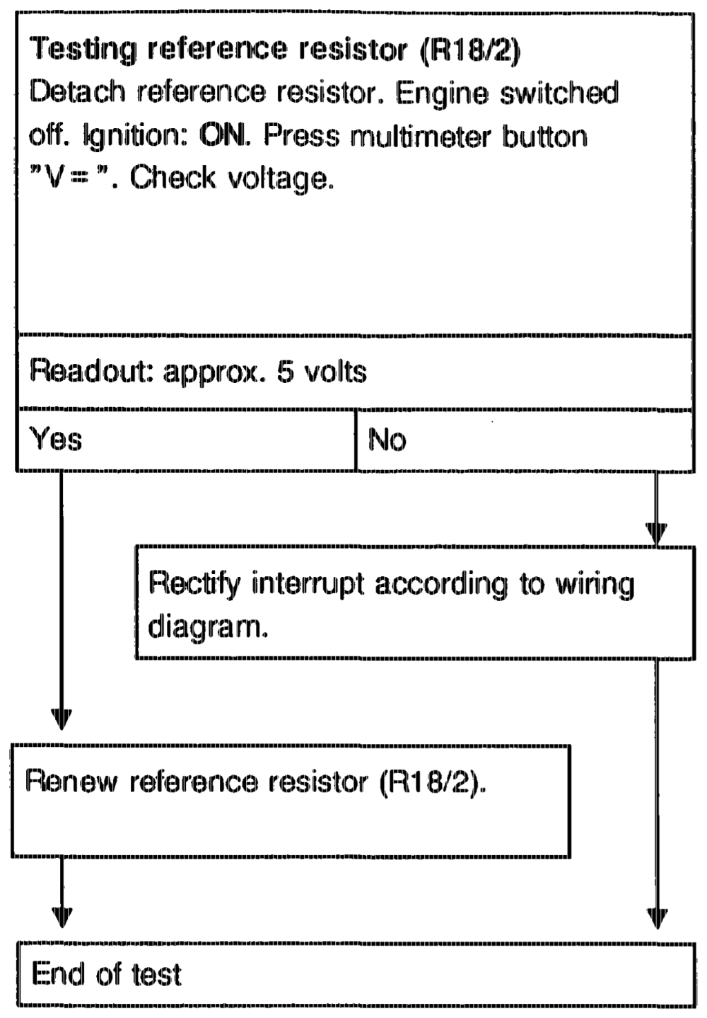
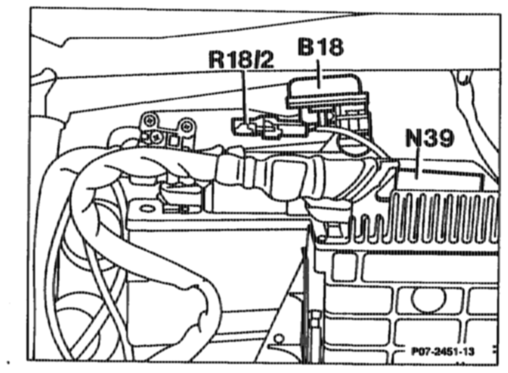
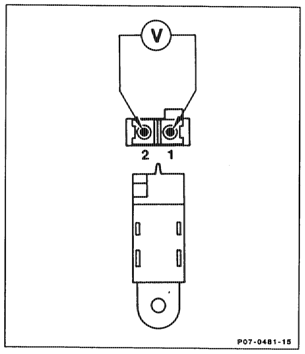
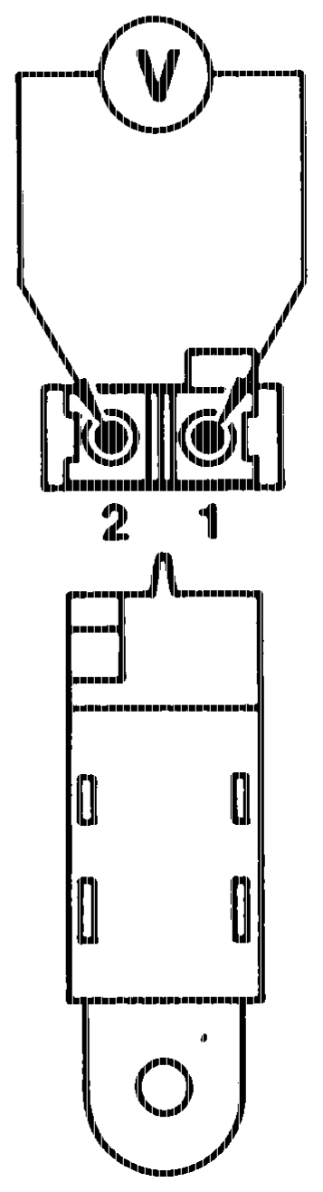
Fault readout ”10”
Note When renewing the reference resistor (R18/2) fit only plug with an identical part no.
catty = RA 07.1.1042-1120/38
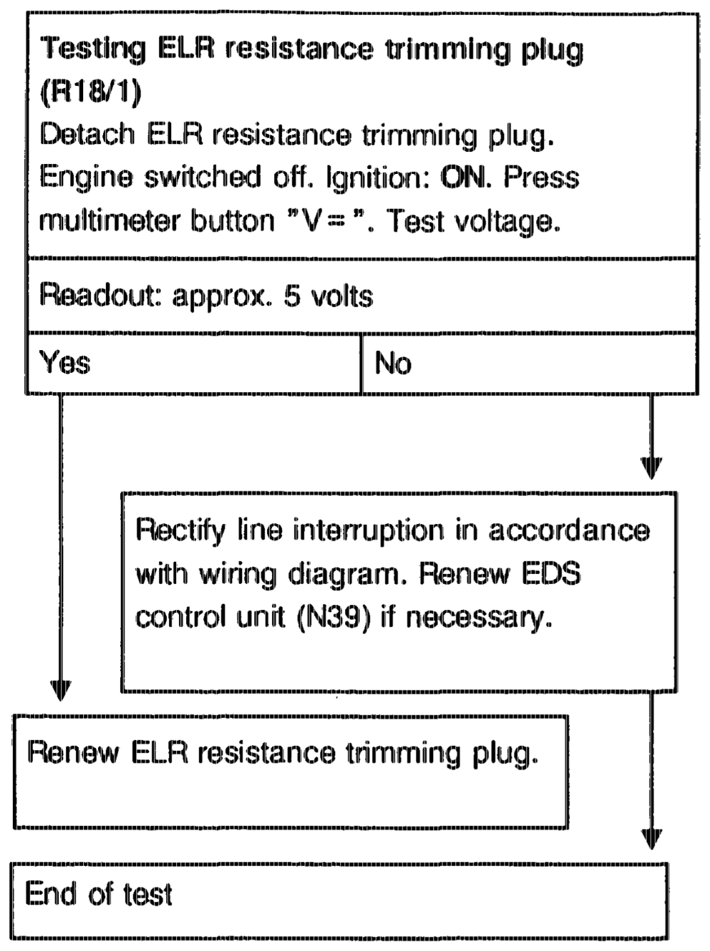
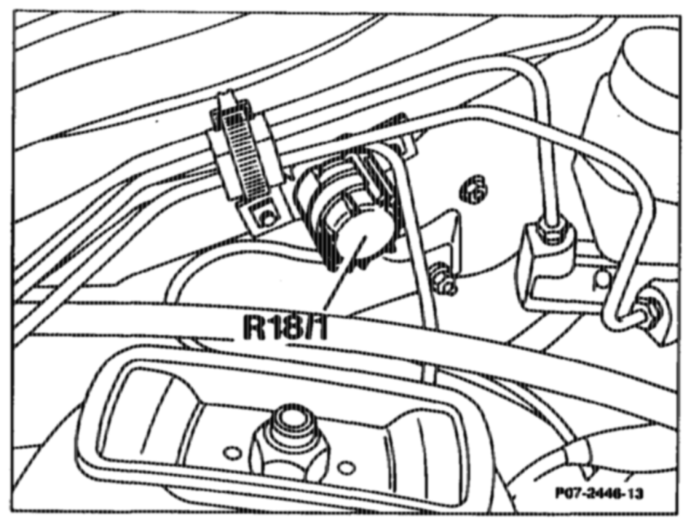
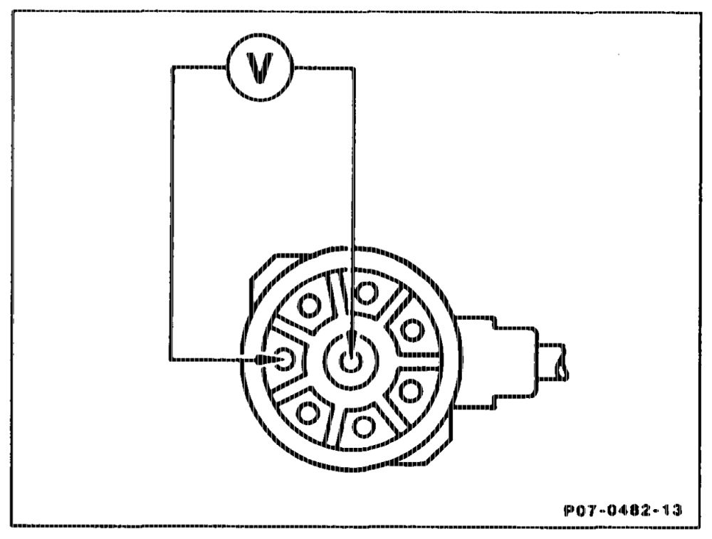
Fault readout °11”
Note The ELR resistance trimming plug (R18/1) is installed in position „4”.
tine RA 07.1.1042~1120/39 c) Testing electronic idle speed control
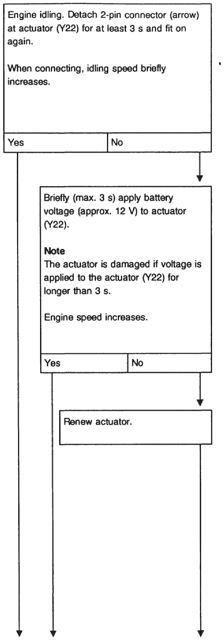
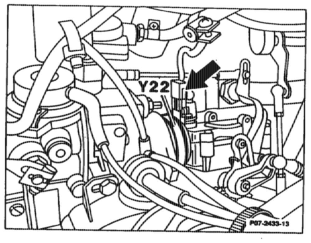
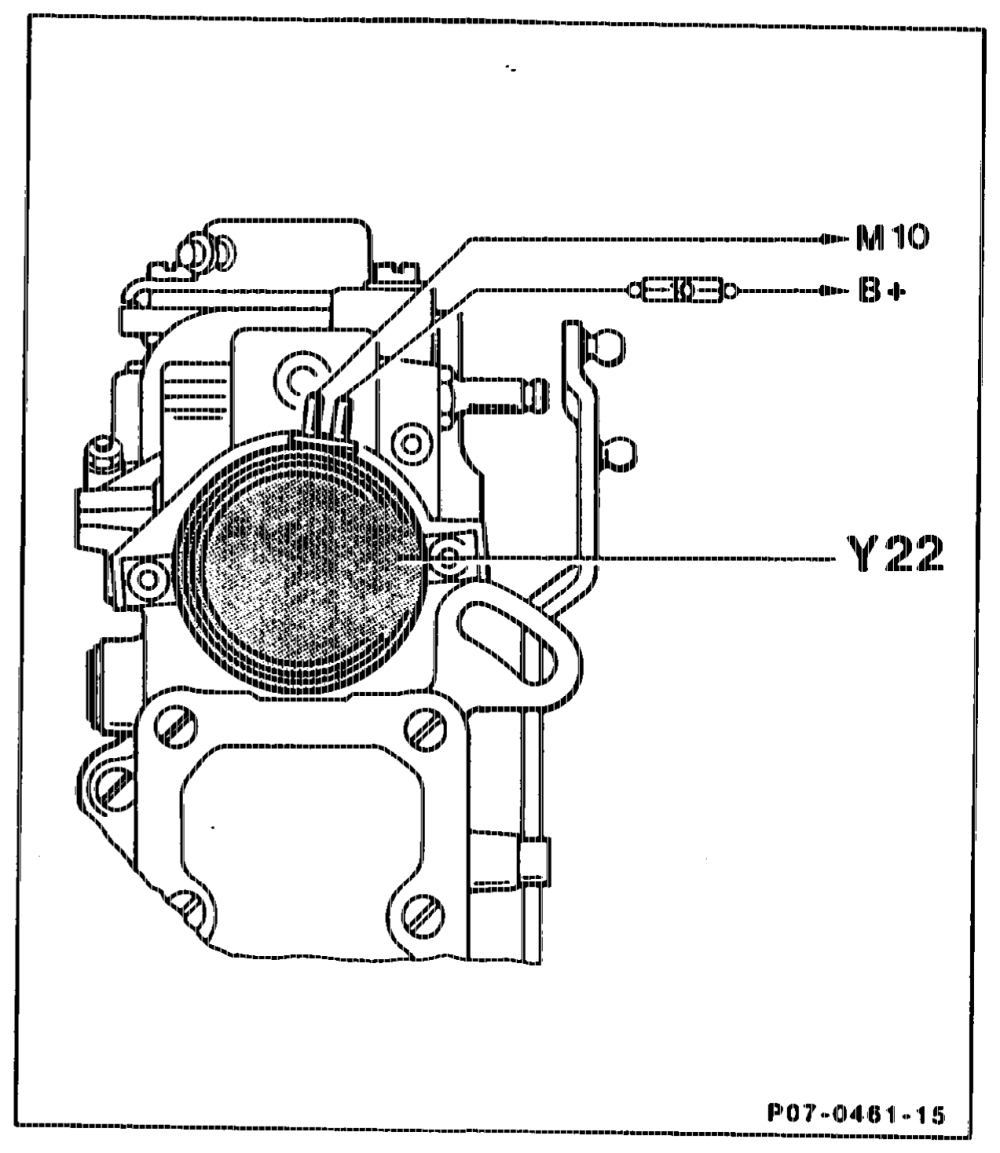
Testing idle speed control
eutiiys = RA 07.1.1042-1120/40
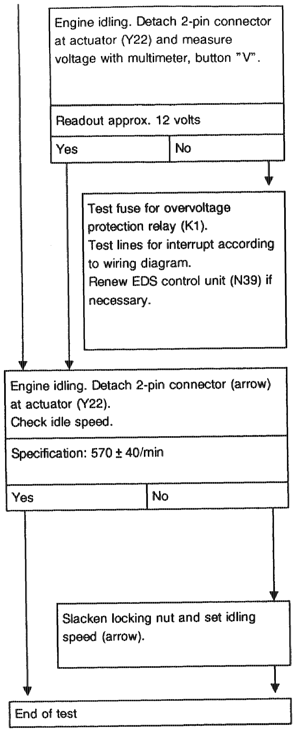
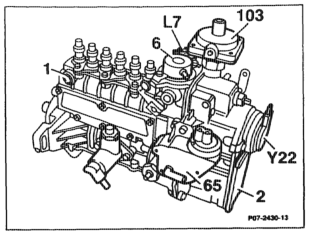
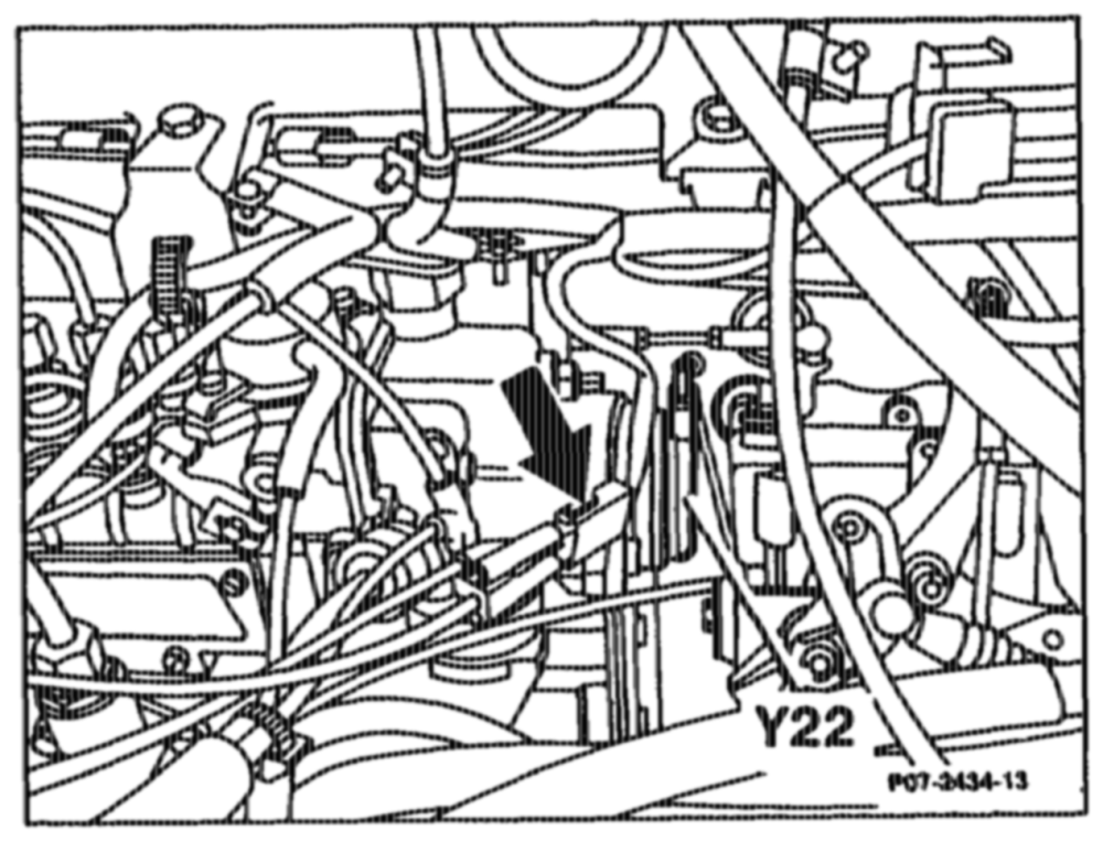
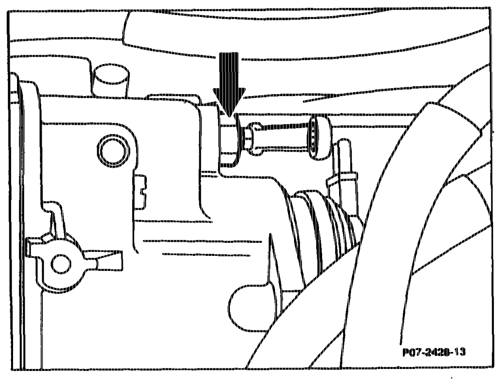
atte = RA 07.1.1042~1120/41
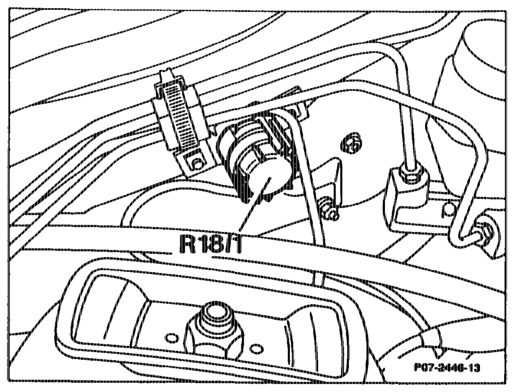
Setting idle speed by means of resistance trimming plug (Ft18/1) If complaints are received regarding idling, idle speed can be altered.
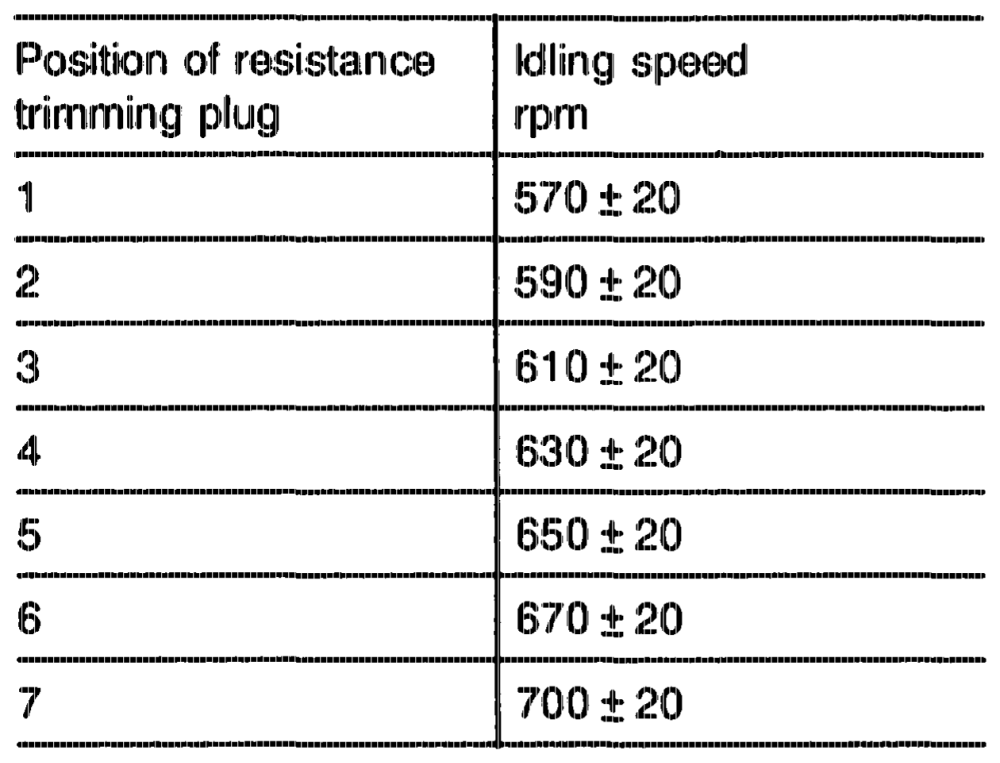
The coded plug positions are listed in the table below.
ptiiagn = RA 07.1.1042~1120/42
C. Engine 603.96, Model 124 Model Year 1988
a) Short-test b) Troubleshooting plan „electronic diesel system” c) ELR and ARF function test
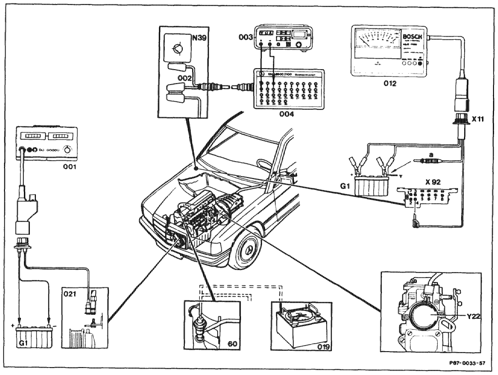
a) Short-test
apts RA O7.1.1042~1120/43
Digital tester (001) and pulse counter (021) ….. connect, disconnect. Larnbda control tester (012) connect, disconnect to battery (G1) and with adapter to test connecter (X92). 9
Contact box (004) …… Leen ene eee eee connect, disconnect with test cable (002) to EDS control unit (N39). Vacuum tester (019) connect, disconnect with Y distributor at ARF valve. Digital multimeter (003) connect, disconnect at contact box (004). Fuse at overvoltage protection relay (K1/1) test.
Selector lever bene e eens move into position „P”. Air conditioning/automatic climate control switch off.
Engine bring to operating temperature (coolant temperature approx. 80 °C).
Note When performing the test work, the intake air hose between air flow sensor and exhaust gas turbocharger must be fitted, otherwise no signal will pass from the air flow sensor to the EDS control unit (N39). Connector „@ 6… ee eee see oe hold approx. 1 second to battery ground, 100 % readout. Connector „a” ….. scene eee eee none take off. 0 % readout, no fault in system. Readout fluctuates, fault in system (refer to troubleshooting table).
If interruption in engine speed sensor (L3) = constant readout = 100 %
Fault stored In system Readout fluctuates and indicates stored fault.
Note One pulse = 0% 100% ~0 %
The number of pulses indicates which electrical component is faulty and whether components in the control circuit are faulty.
Repeat test stap until no further pulse is displayed.
apts = RA 07.1.1042~1120/44
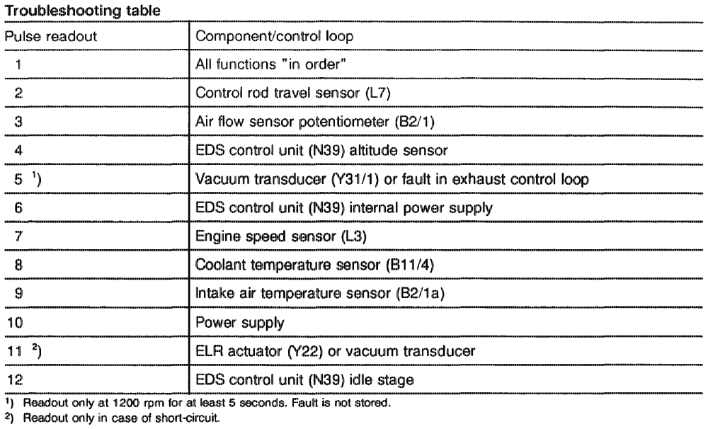
Refer to sections b, and c for further tests.
Note indicated faults and rectify according to troubleshooting schedule (section ”b”).
Erasing fault memory is performed after completing repairs. Each pulse displayed must be erased after termination of the last deflection by connecting pin „a” to battery ground for between 6 and 8 seconds. 2-pin connector on ELR actuator (¥22) detach and fit on again (for at least 3 seconds) Engine speed increases briefly. Engine ………. seesaw see swe run at approx. 1200 rpm and set approx. 250 mbar vacuurn. Briefly apply full throttle. Vacuum drops to 0 mbar. Engine 2… cc ee eee sees switched off.
Pressurize ARF valve at approx. 300 mbar vacuurn ARF vaive is heard to close.
otis = RA 07.1.1042–1120/45 b) Troubleshooting schedule in „electronic diesel system”
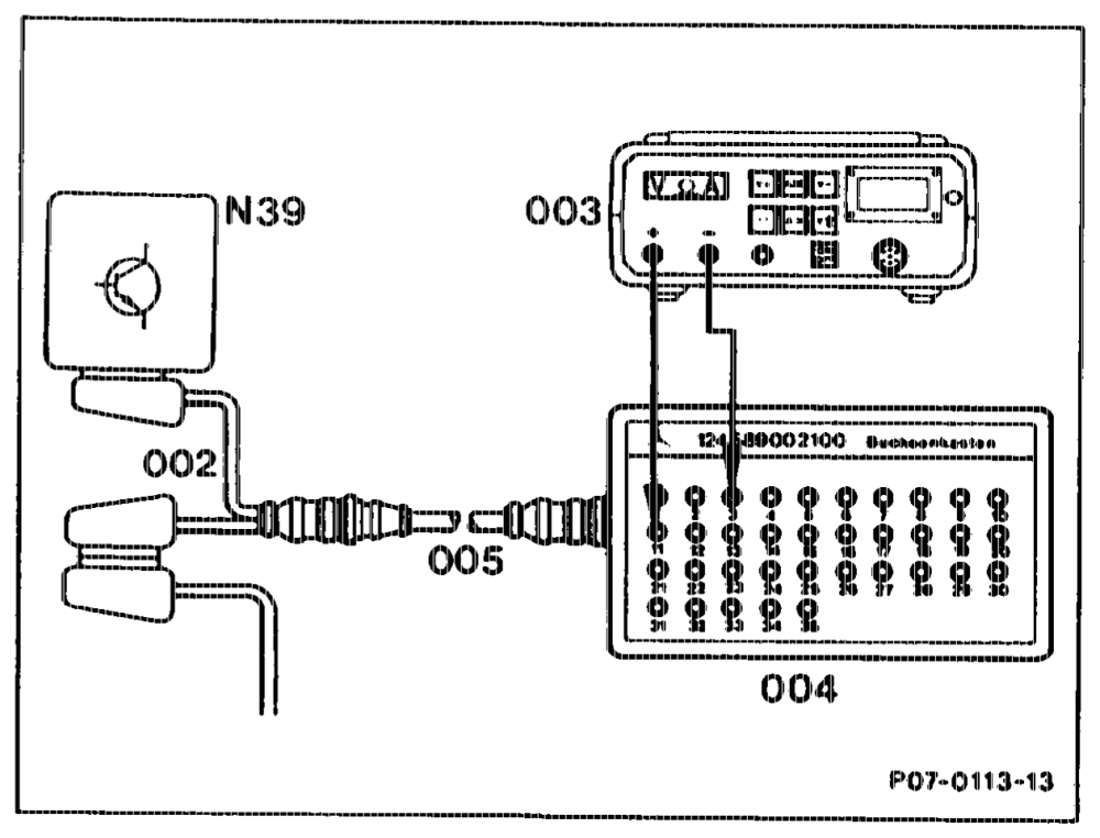
Connection diagram contact box
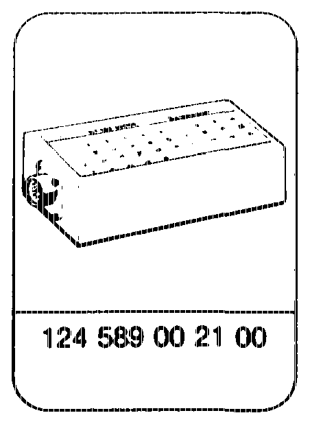
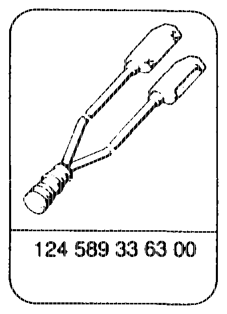
002 25-pin cable hamess, 124 589 33 63 00 003 Multimeter 004 Contact box 124 589 00 21 00 005 Test cable 124 589 34 63 00 N39 EDS control unit
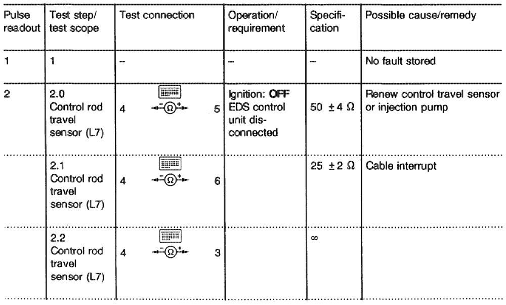
Test program with contact box Note lf the pulse readout is constant, first perform Symbols for test instruments: test steps 1–3. If the specified value of a test step, e.g. step 7, is in order, it is then no longer Contact box necessary to perform test step 7.1. Lambda tester EA Battery Multimeter Contact aw Pin
agtiin = RA 07.1.1042-1120/46
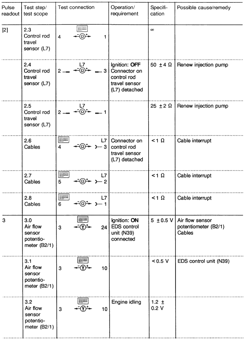
aptiine = RA 07.1.1042~-1120/47
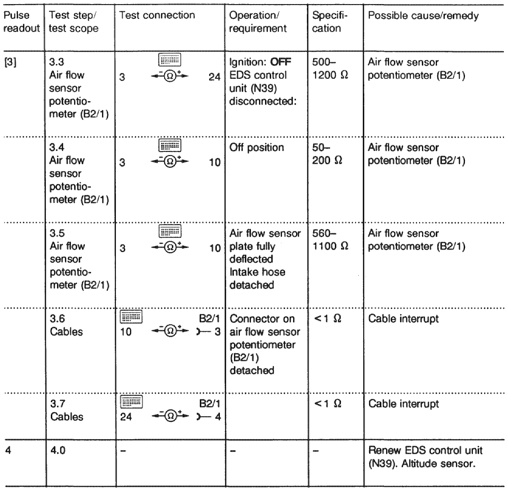
aptiiyy = RA 07.1.1042~1120/48
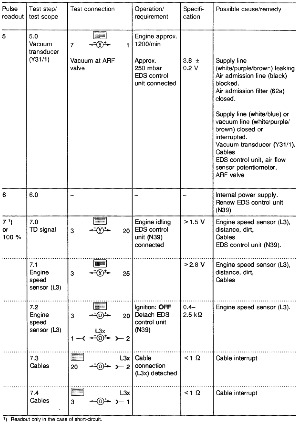
phi = RA 07.1.1042-1120/49
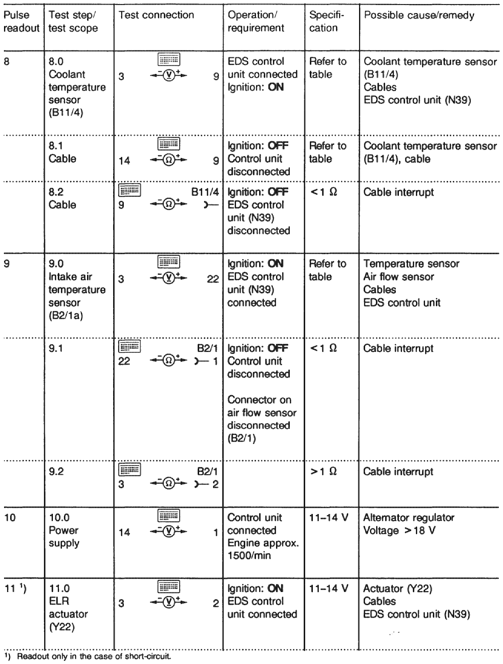
gti = RA 07.1.1042-1120/50
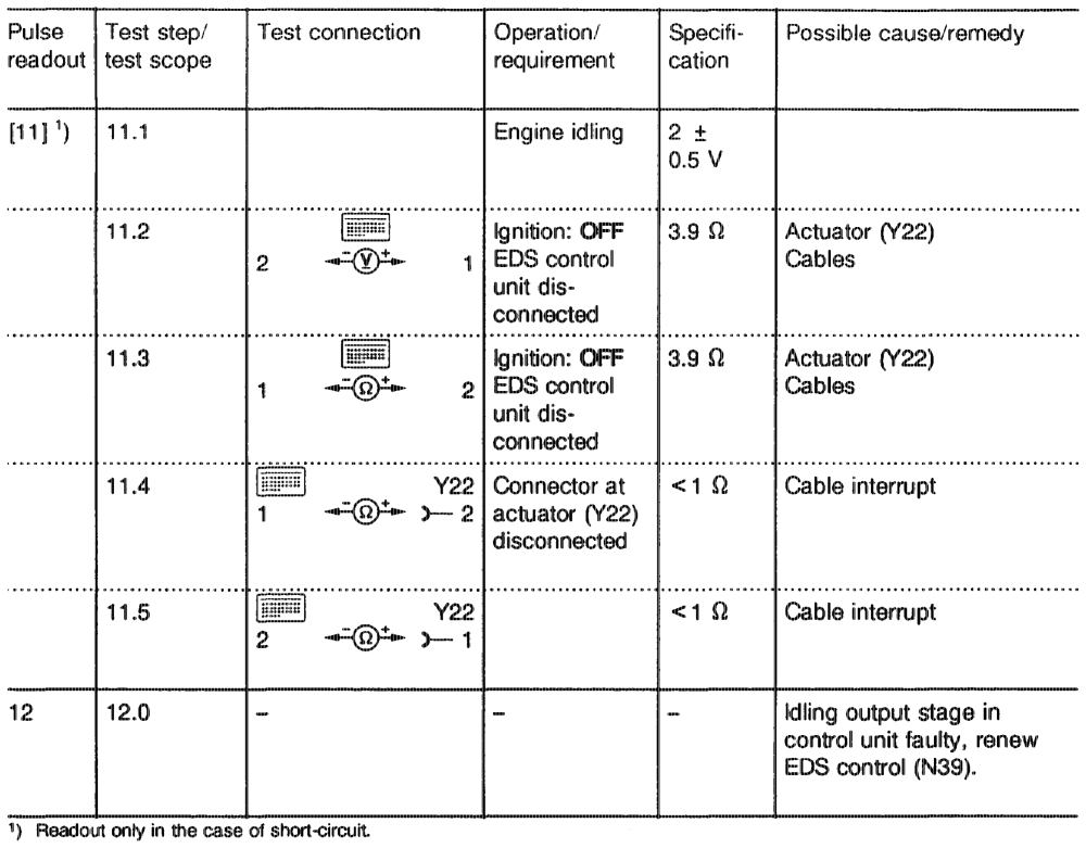
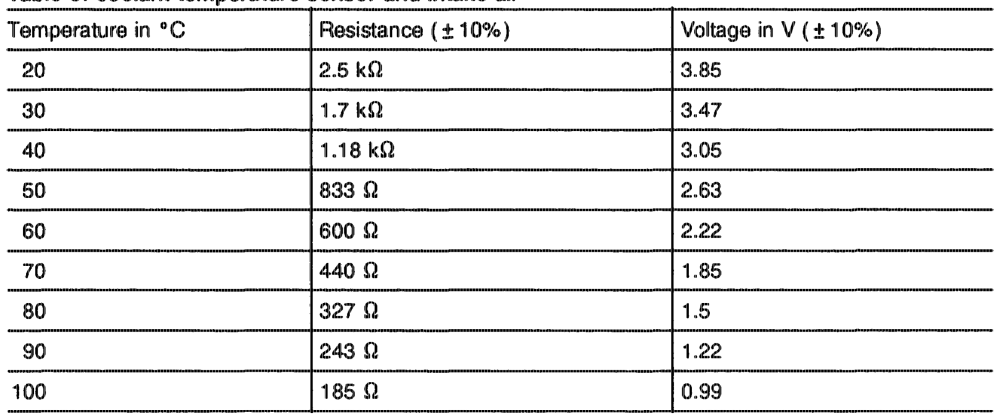
Table of coolant temperature sensor and Intake alr
git. = RA 07.1.1042-1120/51 c) ELR and ARF function test
Note
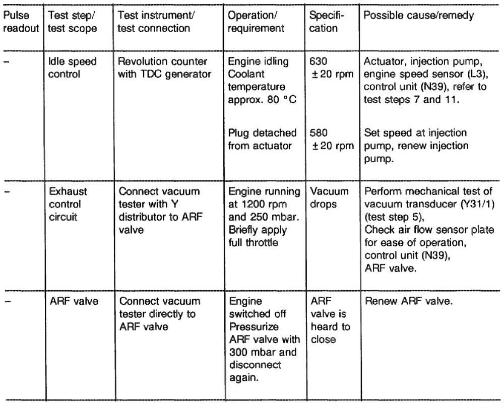
This test should be conducted if complaint has been received but no fault is indicated on the pulse readout.
pty = RA 07.1.1042-1120/52
§ 602.96 and 603.96, Models 124 and 201 D. Engine
a) Short-test b) Testing with pulse counter c) Troubleshooting schedule „electronic diesel system” d) ELR and ARF function test
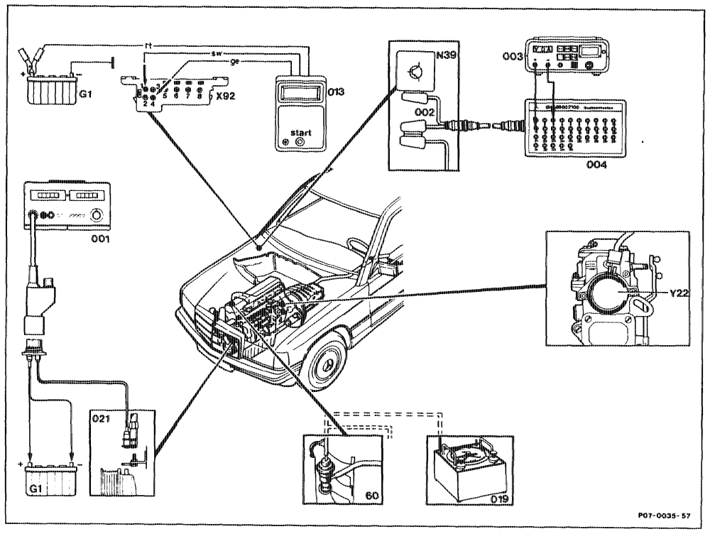
a) Short-test
connect, disconnect. Digital tester (001) and pulse counter (021) ….. Pulse counter (013) 6. eee eee connect, disconnect to battery (G1) and with adapter to test connector (X92) connect, disconnect with test cable (002) to Contact box (004) see eee EDS control unit (N39).
eotitajm = RA 07.1.1042–1120/53
Digital multimeter (003) connect, disconnect at contact box (004). Vacuum tester (019) connect, disconnect with Y distributor at ARF valve.
Fuse at overvoltage protection relay (K1/1) test. Selector lever… Lene e cece eens move into position ”P”. Air conditioning/automatic climate control switch off. Engine 0.0… ee ee eee eee bring to operating temperature (coolant temperature approx. 80 °C). Start button of pulse counter (013) ……….. operate for 2~4 seconds. Display… ee ee eee eee an read off and note. Start button 2… ee ce eee press once again. If no new display appears, there is no further fault in the system.
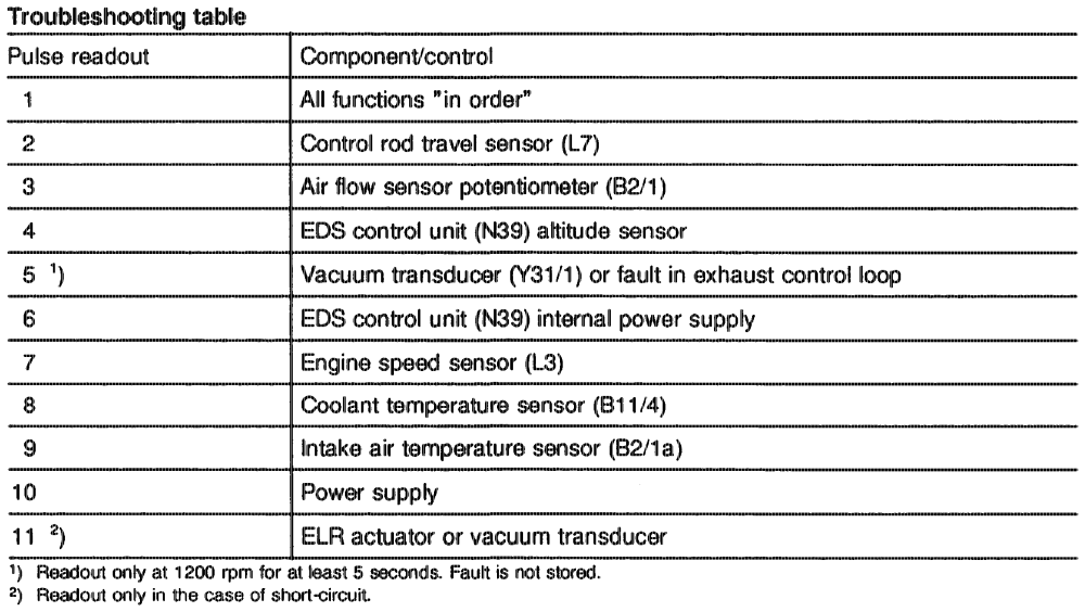
The number of pulses indicates whether and which electrical component is faulty and whether cornponents in the control circuit are faulty.
Refer to sections b, c and d for further tests.
qgthinn = RA 07.1.1042-1120/54 b) Testing with pulse counter
Notes regarding pulse readout If a complaint is received but no fault is indicated on the pulse readout, perform the function test, section „d”. The number 1 indicates no fault detected in the electronic system. All other numbers are assigned to a particular fault group. The numbers from 1 to 11 appear on the display of the pulse counter.
® tthe LED U-Batt appears after connecting, pulse count and pulse supply for the pulse counter are in order.
Testing ® Connect pulse counter as shown in connection diagram.
Note LED U-Batt in display panel must light up; if not: a) test fuse of pulse counter b) test jack 1 of test connector (X92 or X11/4) to battery positive (11–14 V). c) test jack 4 of test connector (X92 or X11/4) to jack 1 (2–6 V).
agin = RA 07.1.1042~1120/55
® Engine idling. ® Operate start button for between 2 and 4 seconds. ® Take readout of pulse output and note. ® Again press start button for between 2 and 4 seconds. If no fault exists in the systern, the previous readout appears once again. ® Rectify noted faults (pulse readout) according to troubleshooting schedule. ® Perform components test.
st 1g fault memory After a fault has been rectified, the pulse displayed must be erased as follows: © Operate start button and readout the rectified fault, then press start button for 6–8 seconds.
Note Each displayed pulse must be erased individually. ® No readout: stored fault is erased. ® Display of a number (larger than 1), further faults in system.
aphinn = RA 07.1.1042-1120/56
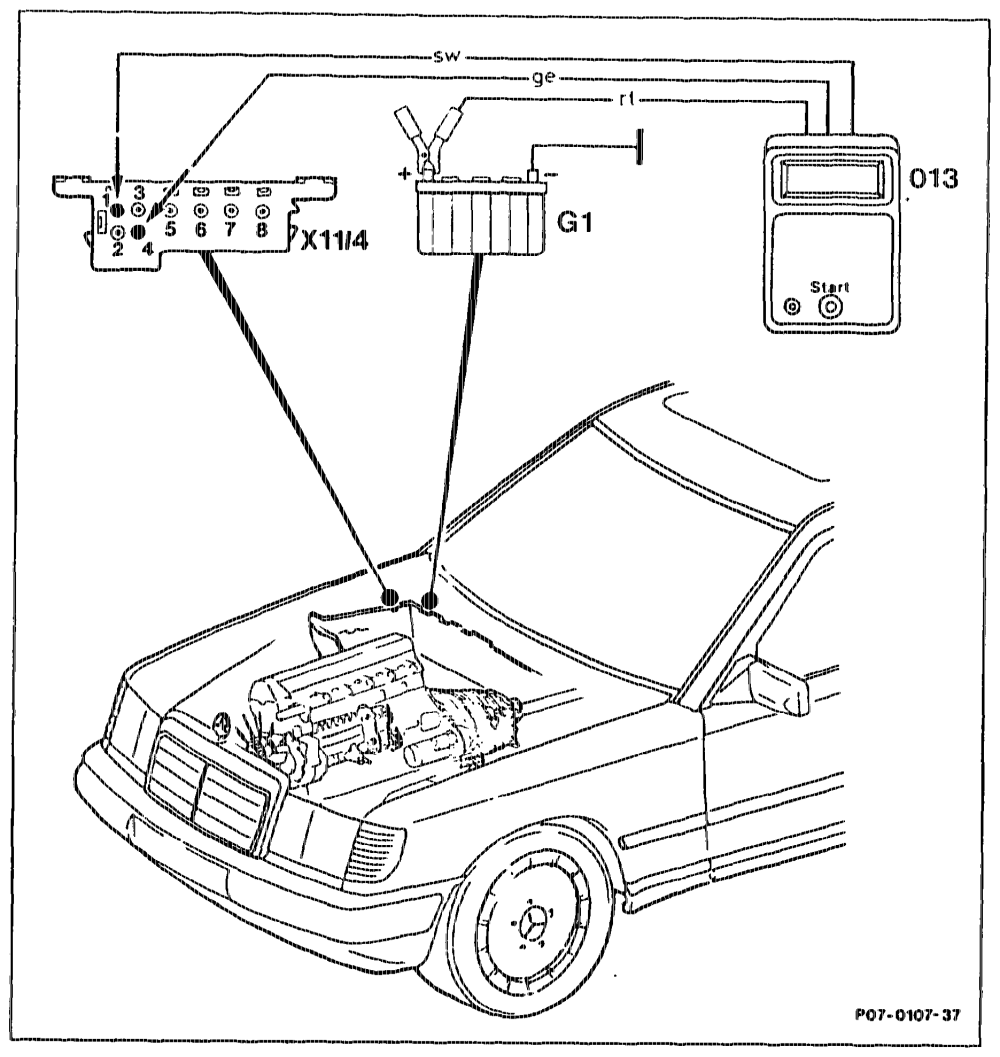
Connection diagram
013 Pulse counter X11/4 Test connector for diagnostics G1 Battery
Test connector for diagnostics X11/4)
4 Ground
2 TD signal
3 Exhaust test signal (only for production tuning)
4 Diagnostic signal
apthiayy = RA 07.1.1042-1120/57
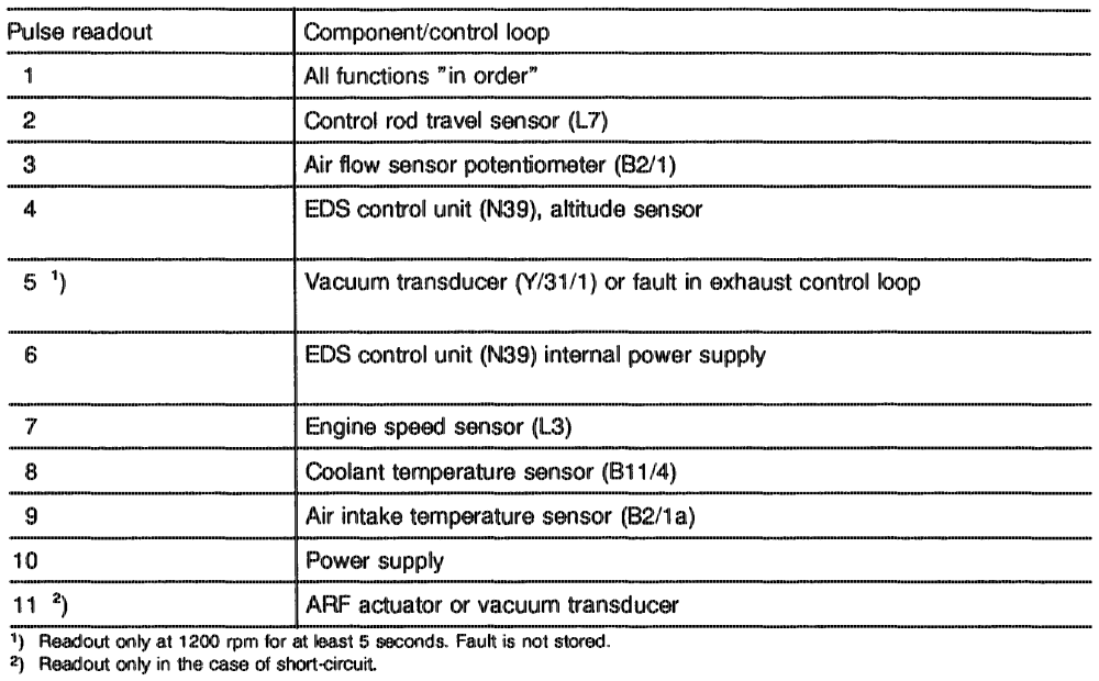
The number of pulses indicates whether and which electrical component is faulty and whether cornponents in the control circuit are faulty.
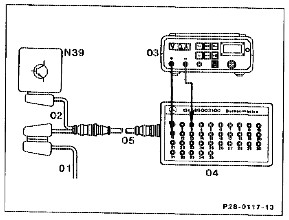
Connection diagram comtact Ox
001 ©25-pin cable hamess 002 25-pin test cable 124 589 33 63 00 003 = Multimeter 004 Contact box 124 589 00 21 00 005 Test cable 124 589 34 63 00 N39 EDS control unit
otiiim = RA 07.1.1042–1120/58 c) Troubleshooting schedule „electronic diesel system”
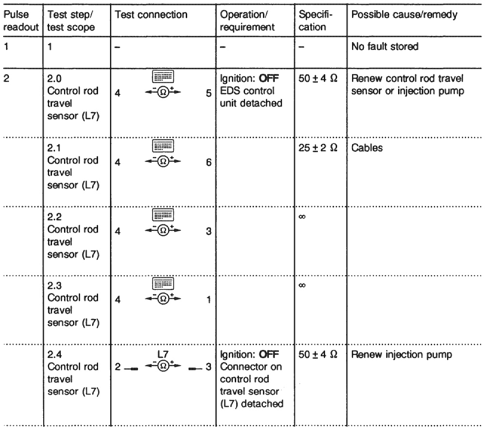
Symbols for test instruments: Note If the pulse readout is constant, first perform Contact box test steps 1–3. If the specified value of a test Lambda sensor step, e.g. step 7, is in order, it is not then Ea Battery necessary to also perform test step 7.1. Multimeter Contact ——_ Connecting pin
auttiayn = RA 07.1.1042-1120/59
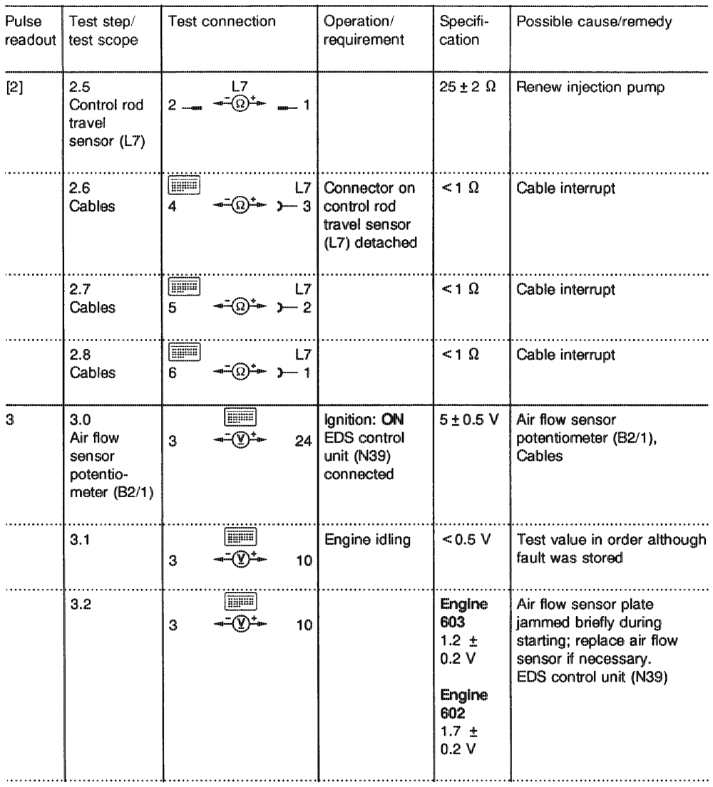
epi. = RA 07.1.1042-1120/60
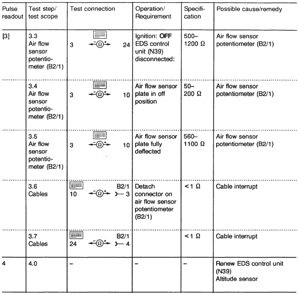
phi = RA O7.1.1042-1120/61
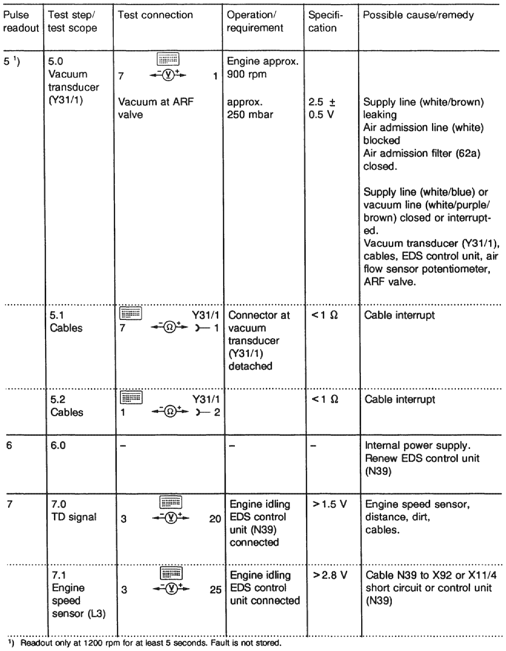
aplihis = RA 07.1.1042-1120/62
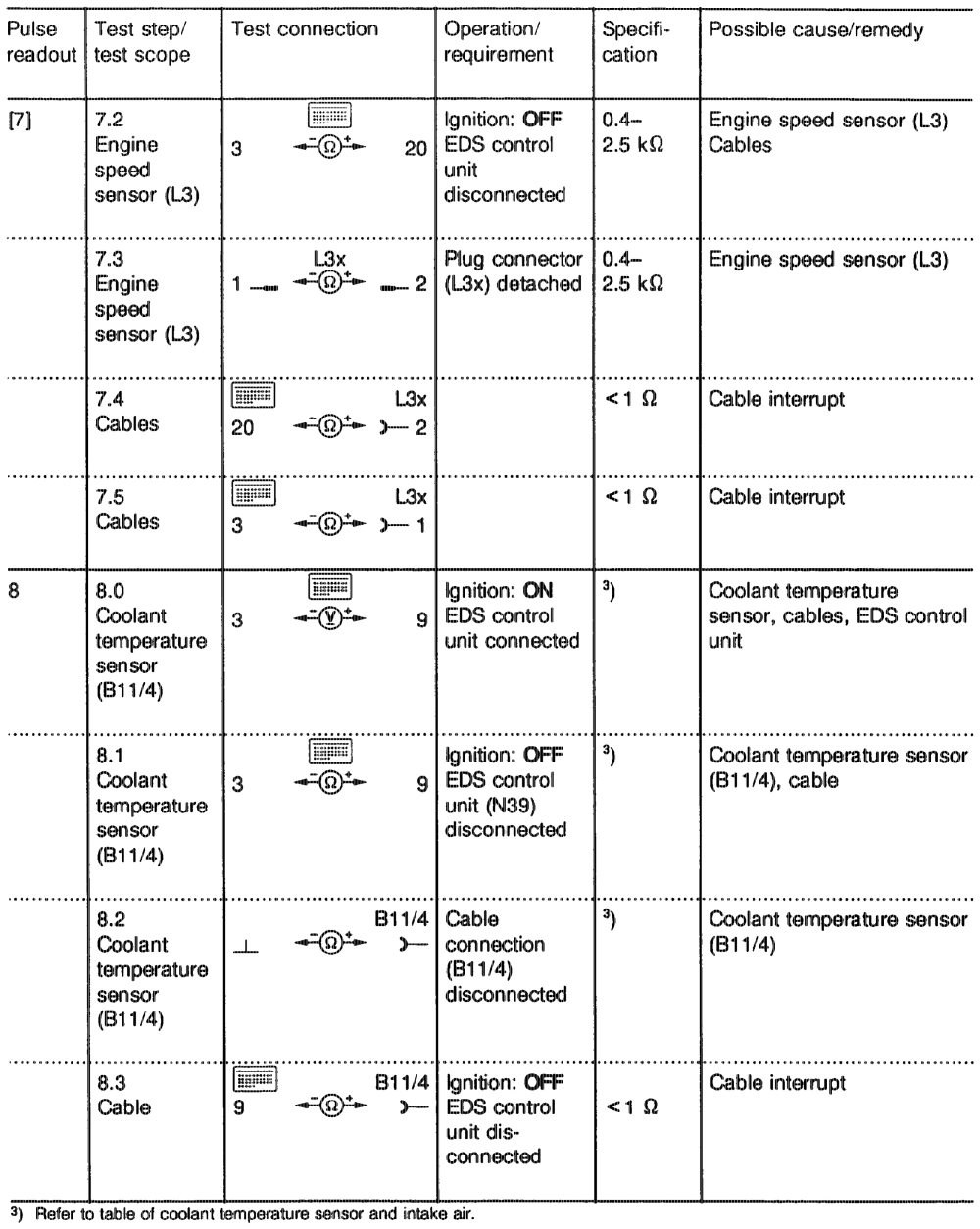
aptiae RA 07.1.1042~1120/63
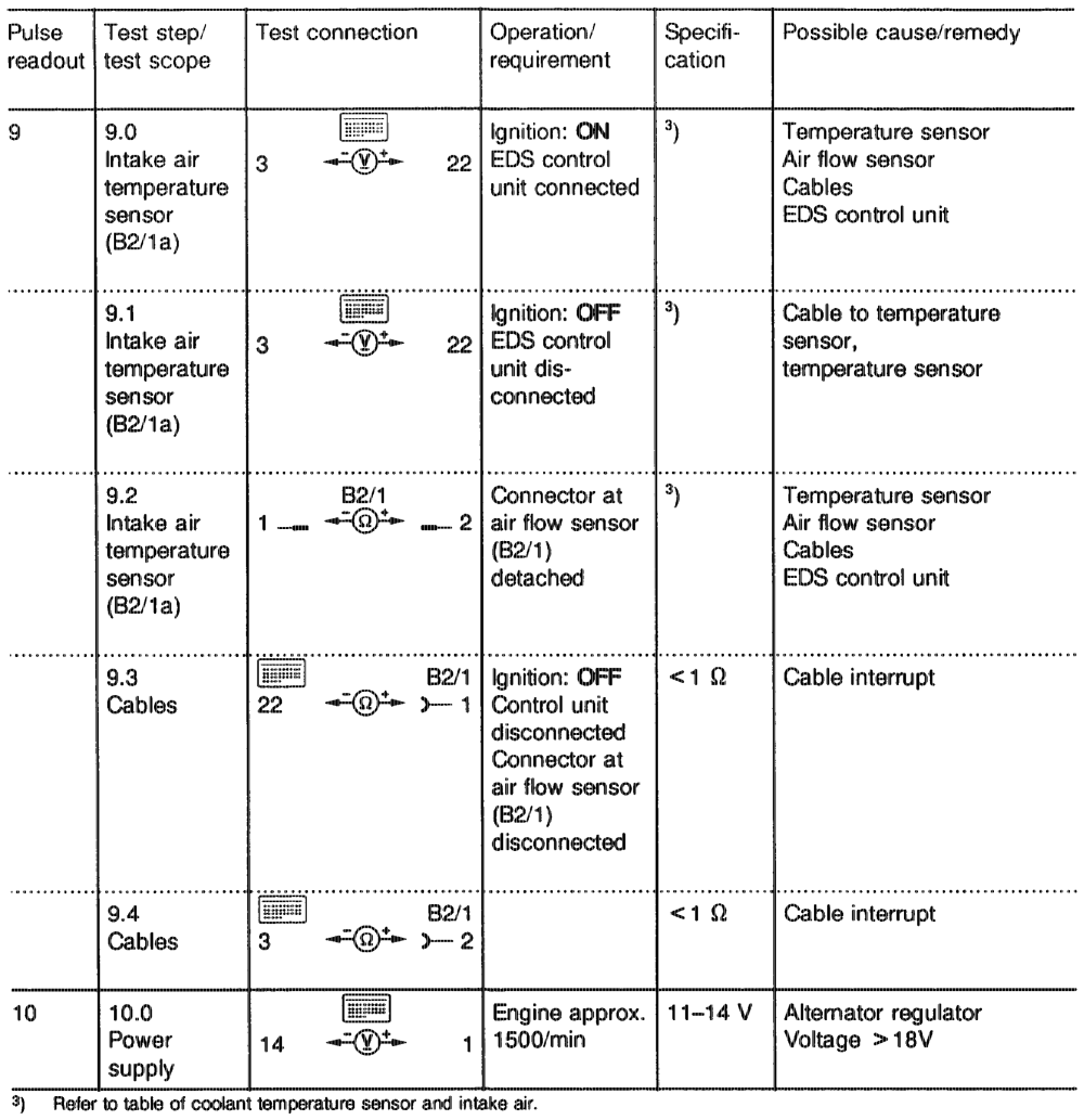
thingy = RA 07.1.1042–11 20/64
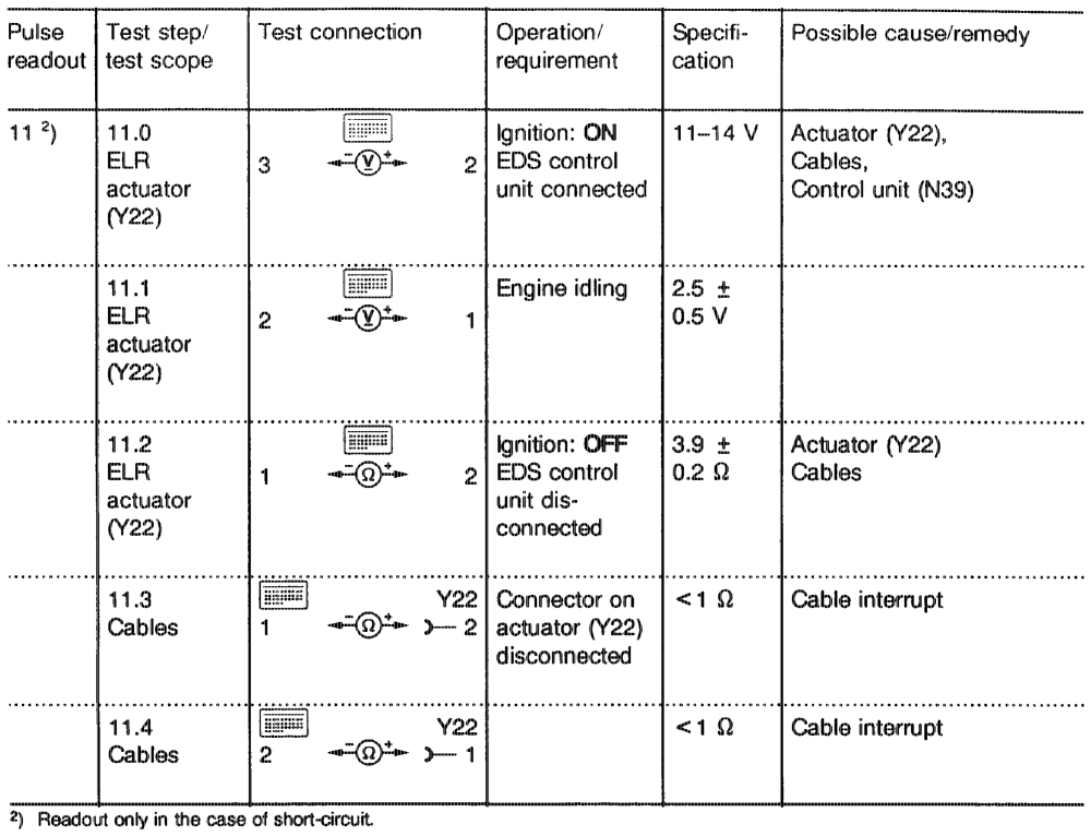
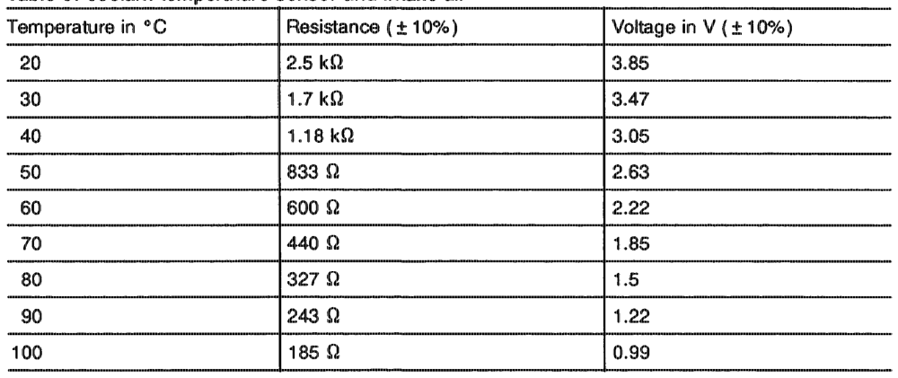
Table of coolant temperature sensor and intake air
whinn RA 07.1.1042-1120/65 d) ELR and ARF function test
Note
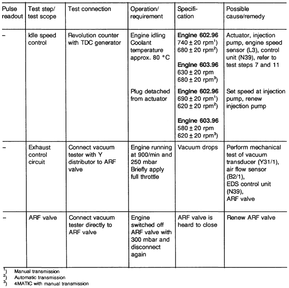
This test is to be conducted if complaint has been received but no fault is indicated on the pulse readout.
tian = RA Q7.1.1054~1120/66
E. Engines 602.96 and 603.96 G> model year 1990 and @) model year 1991
a) Short-test b) Testing with pulse counter c) Troubleshooting schedule d) Teast program with contact box e) ELR and ARF function test
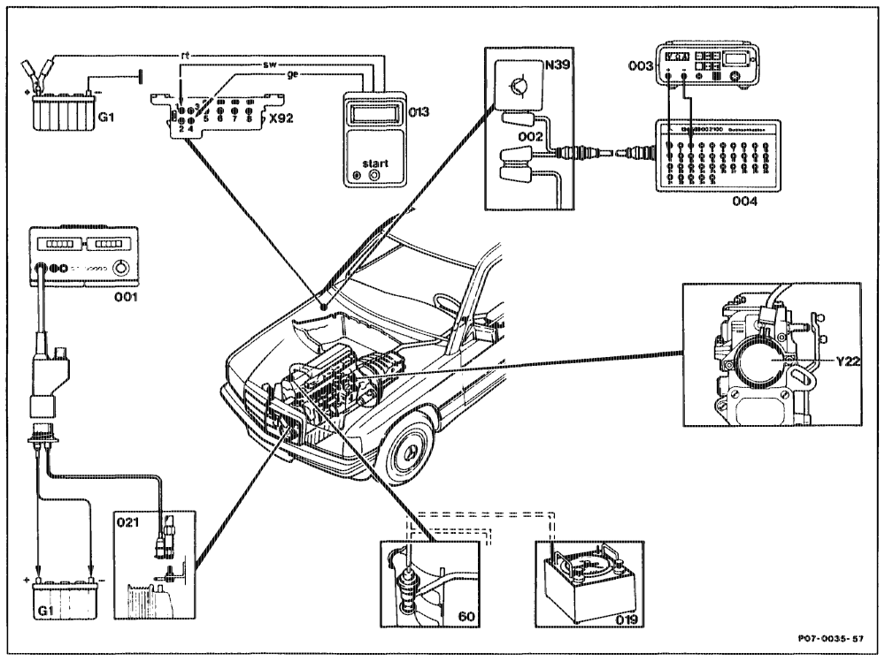
a) Short-test
agtiiyn = RA 07.1.1042~1120/67
Digital tester (001) and pulse counter (021) ….. connect, disconnect. Pulse counter (013) 6… kee eee ee eee connect, disconnect to battery (G1) and with adapter to test connector (X92 or X11/4). Contact box (004) 6… eee ee connect, disconnect with test cable (002) to EDS control unit (N39). Digital multimeter (003) 6… eee ee ee eee connect, disconnect at contact box (004). Vacuum tester (019) 2.6… wee eee ee ee connect, disconnect with Y distributor to ARF valve.
Fuse at overvoltage protection (K1/1) ……… test. Selector lever oe ee eee move into position „P”. Air conditioning/automatic climate control …… switch off. Engin® 20… ee eee eee tee bring to operating temperature. (Coolant temperature approx. 80 °C) Start button of pulse counter (013) ……….. operate for 2–4 seconds. Display 6. cee eee ee eee read off and note. Start button oo… eee ee eee press once again. If no new display appears, there are no further faults in the system.
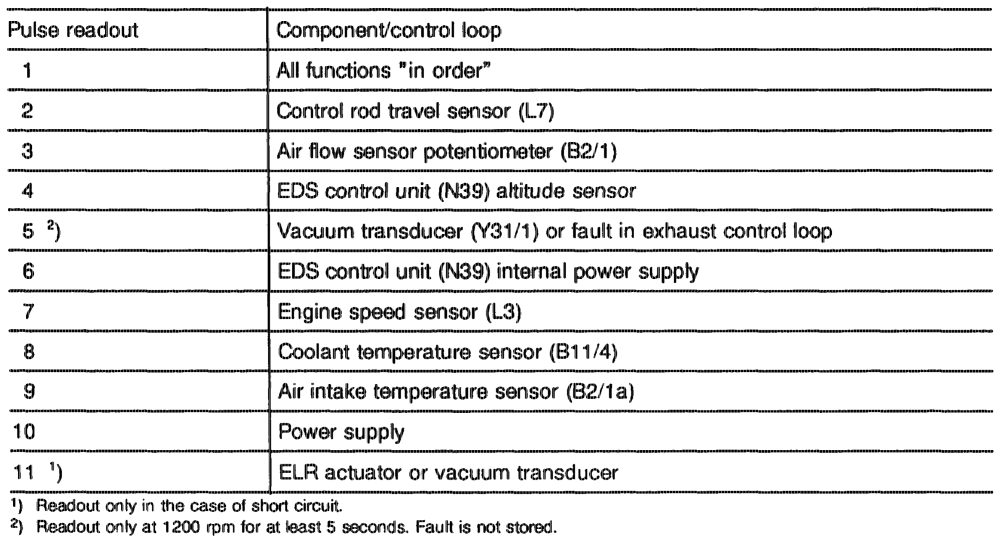
The number of pulses indicates whether and which electrical component is faulty and whether components in the control circuit are faulty.
eotiiayn = RA 07.1.1042-1120/68 b) Testing with pulse counter
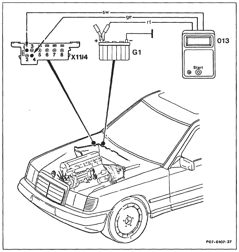
Connection diagram
013° = Pulse counter X11/4 Test connection for diagnostics Gi Battery
Assignment (X11/4)
1 Ground
2 TD signal
3 Pulse output ARA control unit (N8/2)
4 Pulse output EDS control unit (N39)
Notes regarding pulse readout if a complaint is received but no fault is indicated on the pulse readout, perform the function test, section ”e”. The number 1 indicates no fault detected in the electronic system. All other numbers are assigned to a particular fault group. The numbers from 1 to 11 appear in the display panel of the pulse counter. ff the LED U-Batt appears after connecting, pulse counter and power supply for pulse counter are in order.
agihine = RA 07.1.1042~1120/69
Erasing fault memory Testing
1 Connect pulse counter according to wiring After a fault has been eliminated the pulse diagram. displayed must be erased as follows:
Note 9 Operate start button and read out the LED U-Batt in display panel must light up; if not: eliminated fault, then operate start button for a) test fuse of pulse counter. 6–8 seconds. b) test jack 1 of test connector (X92 or X11/4) to battery positive (11–14 V).
Note c) test jack 4 of test connector (X92 or 11/4) Each fault displayed must be erased individually. If the fault is eliminated and erased, the fault to jack 1 (6–12 V). code no longer appears on the fault output.
2 Engine idling. if a number larger than 1 is displayed, there are further faults in the system.
3 Operate start button for between 2 and 4 seconds.
4 Take readout of pulse output and note. Readout 1” = no fault Greater than „1” = fault in system
§ Operate start button again for between 2 and 4 seconds. If there is no further fault in the system, the previous value appears again. If there is a further fault in the system, its fault code is displayed.
6 Repeat again until the first fault is displayed again.
7 ~~ Eliminate faults noted (pulse output) through troubleshooting program.
8 Perform testing of components.
qgthiajn = RA 07.1.1042-1120/70 c) Troubleshooting schedule
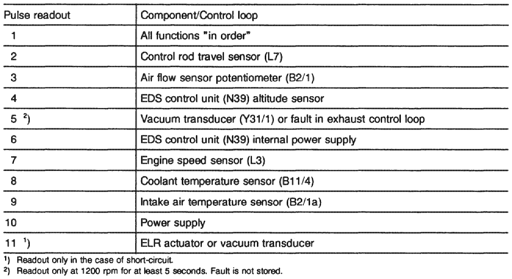
The number of pulses indicates whether and which electrical component is faulty and whether components in the control circuit are faulty.
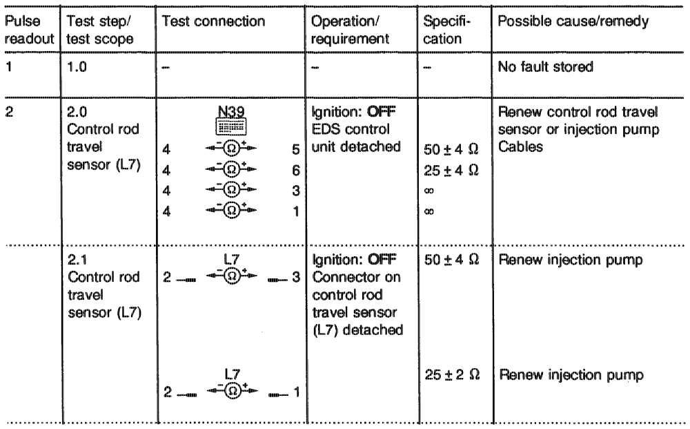
aphiie = RA O7.1.1042-1120/71 d) Test program with contact box
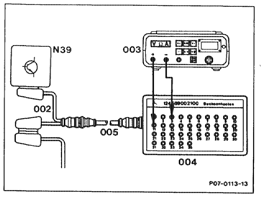
Connection diagram contact box
002 25-pin test cable 124 589 33 63 00 003 Multimeter 004 —35-pin contact box 124 589 00 21 00 005 Test cable 124 589 34 63 00 N39 «EDS control unit
uty = RA 07.1.1062-1120/72
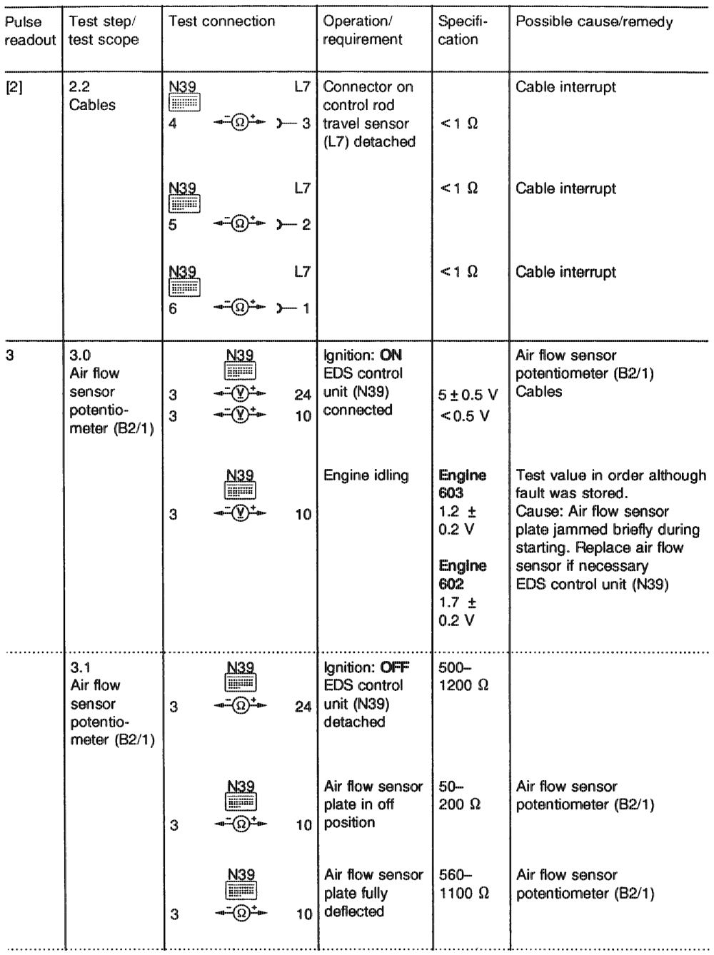
otthiyn RA 07.1.1042-1120/73
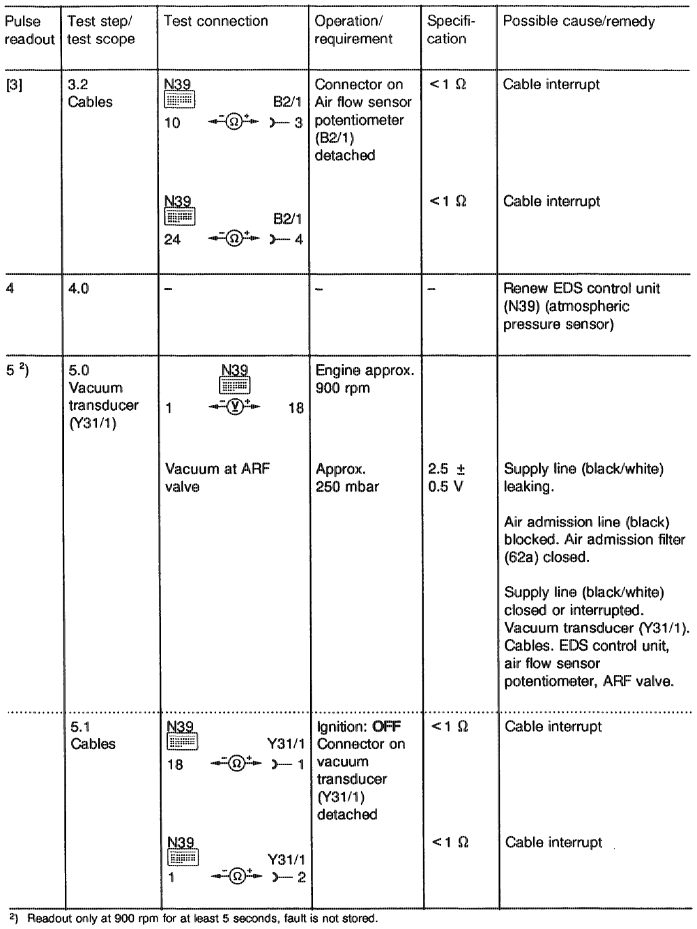
RA 07.1.1042-1120/74
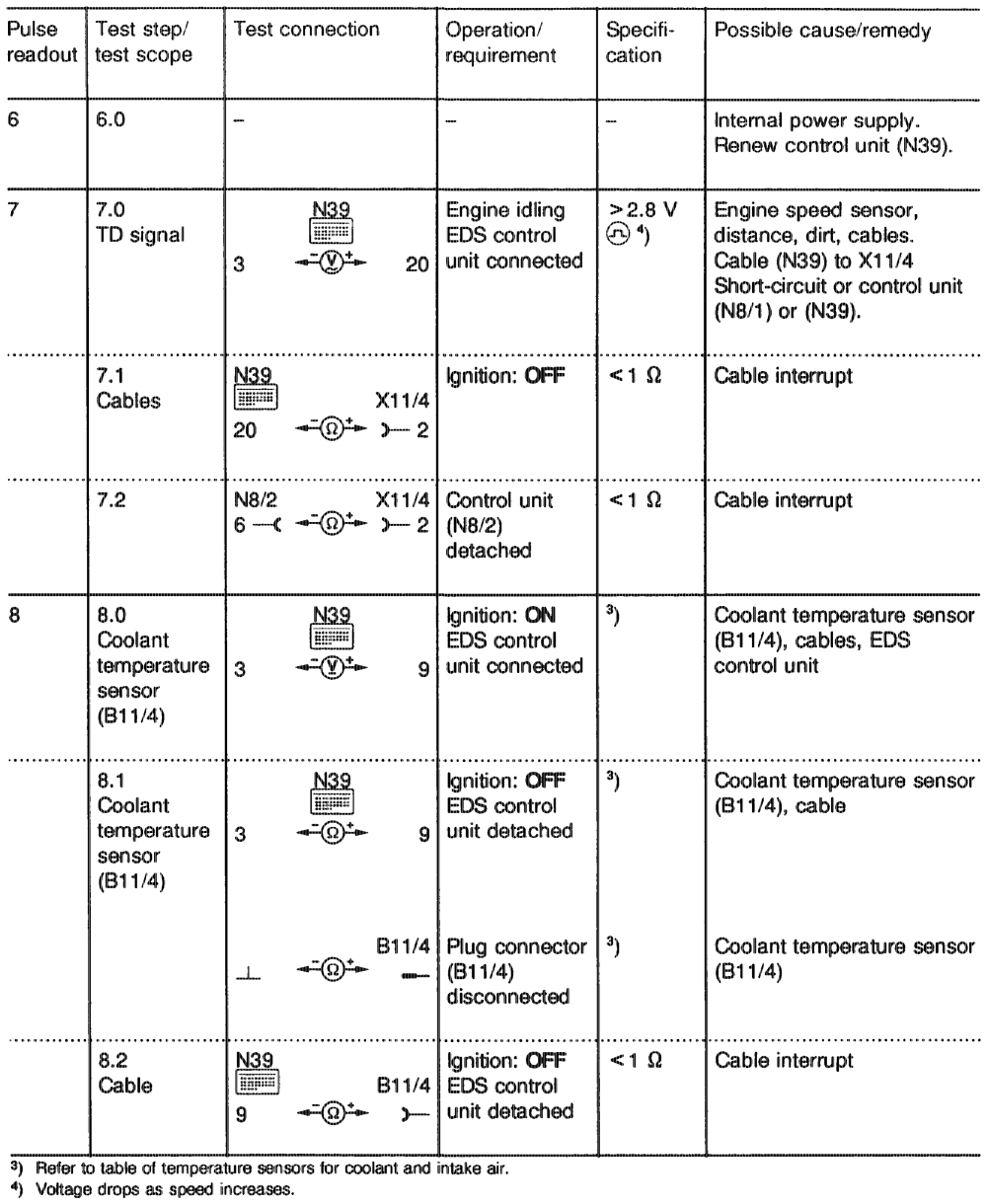
utiis = RA O7.1.1042-1120/75
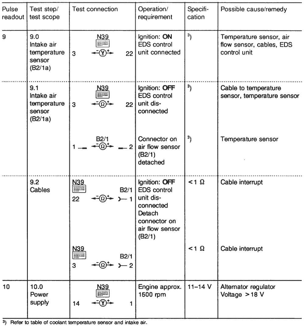
optim = RA 07.1.1042-1120/76
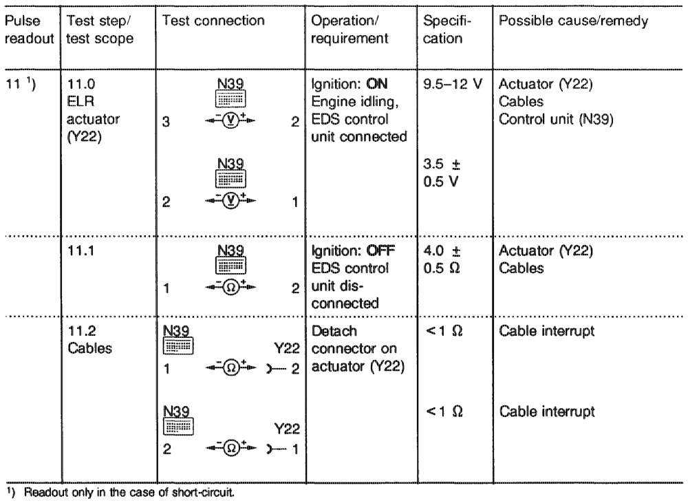
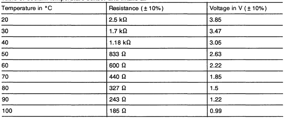
Table of coolant temperature sensor and Intake air
eptitajim = RA 07.1.1042~1120/77 e) ELR and ARF function test
Note
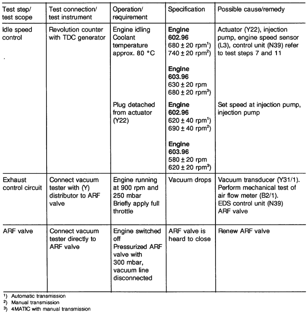
This test should be conducted if a complaint has been received but no fault is indicated on the pulse readout.
wtiiajn = RA O7.1.1054-1120/78
. Engines 602.962 and 603.970, Model Year 1990 Engine 602.962 @) Model Year 1991
Short-test b) Testing with pulse counter c) Troubleshooting schedule qd) Test program with contact box (Engine 602.962) 8) ELR, ARF function test, P2 control Test program with contact box (Engine 603.970) ELR and ARF function test (Engine 603.970) 9)
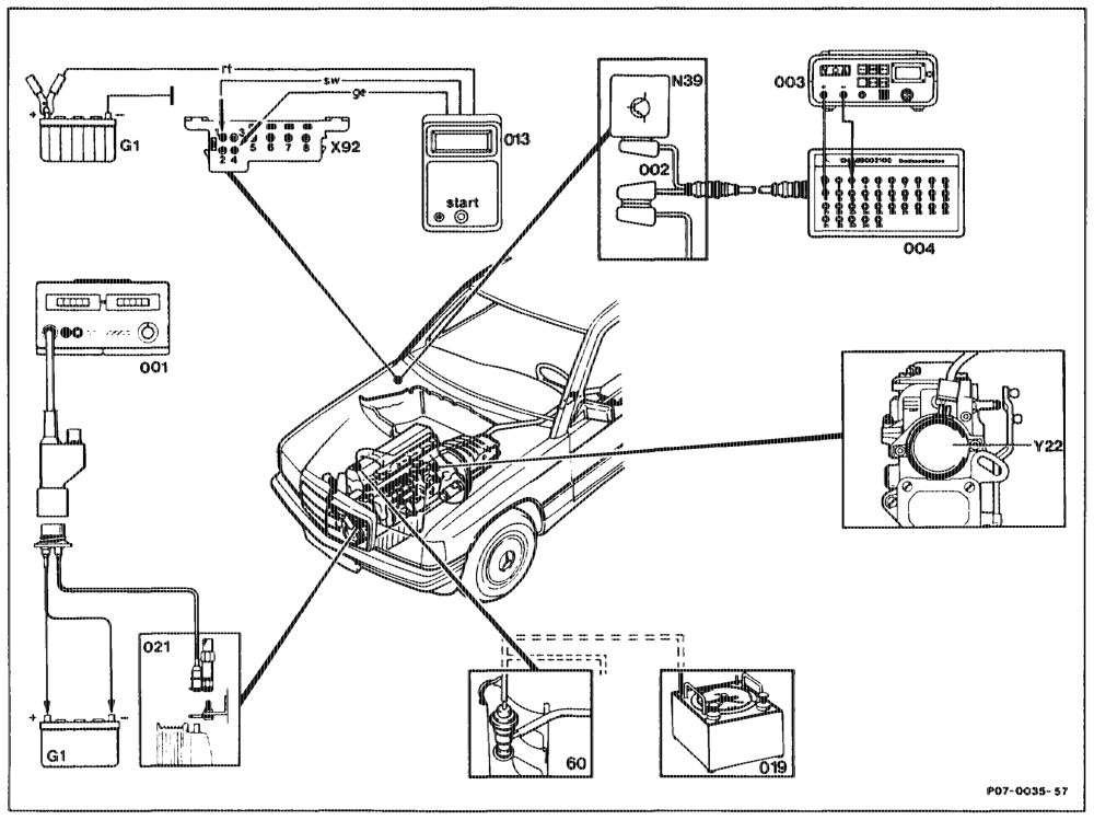
a) Short-test
oti = RA 07.1.1042-1120/79
Digital tester (001) and pulse counter (021) ….. disconnect, connect. connect, disconnect to battery (G1) and with Pulse counter (013) 6… ee eee eee eee adapter to test connector (X92 or X11/4).
Contact box (004) 6. ee eens connect, disconnect with test cable (002) to EDS control unit (N39).
Digital multimeter (003) ww we ee eee connect, disconnect at contact box (004).
Vacuum tester (O19)… eee ee ee eee connect, disconnect with Y distributor at ARF valve. Fuse at overvoltage protection (K1/1) ……… test. Selector lever ok eee eee move into position ”P”. Airconditioning/automatic climate control ……. switch off. Engine 2.0… eee eee eee bring to operating temperature (coolant temperature approx. 80 °C). Start button of pulse counter (013) ……….. operate for 2–4 seconds. Display ce ee eee et eee eee read off and note. Start button 2… cee ee eee ees press once again. If no new display appears, there is no further fault in the system.
eptiiagn = RA 07.1.1042~1120/80
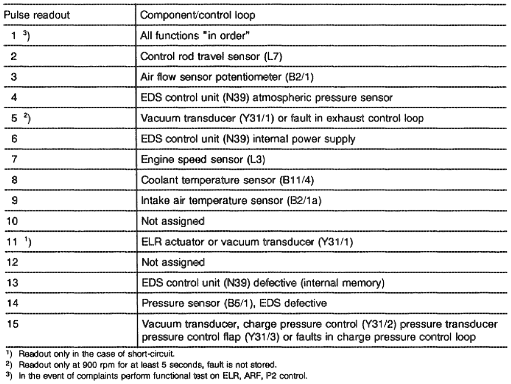
Engine 602.962 The number of pulses indicate whether and which component is faulty and whether components in the control circuit are faulty.
ghia = RA 07.1.1042-1120/81
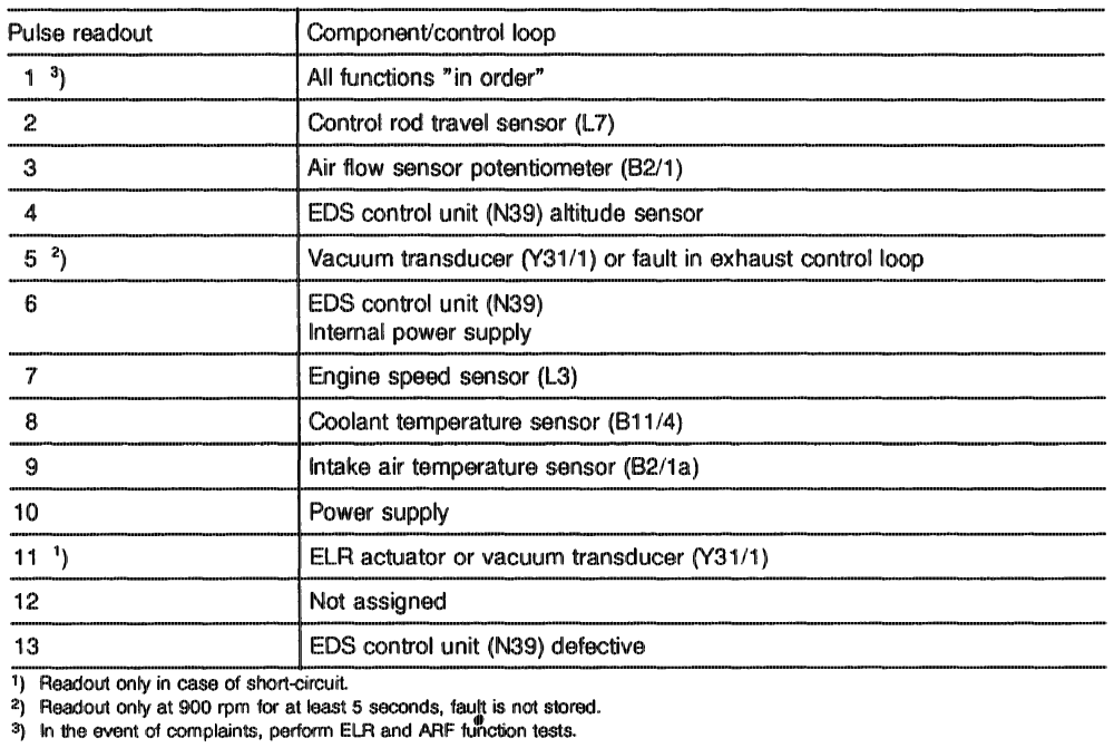
Engine 603.970 The number of pulses indicates whether and which component is faulty and whether components in the control circuit are faulty.
autiin = RA O7.1.1042-1120/82 b) Testing with pulse counter
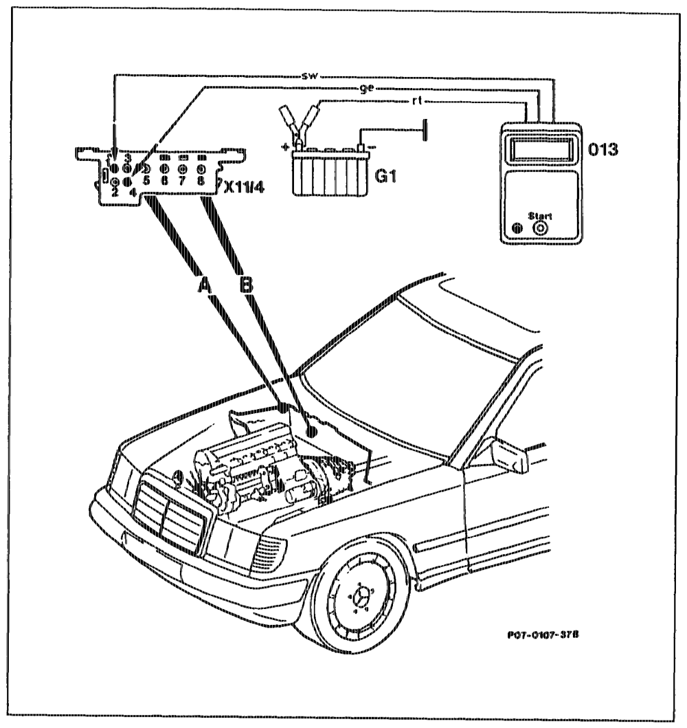
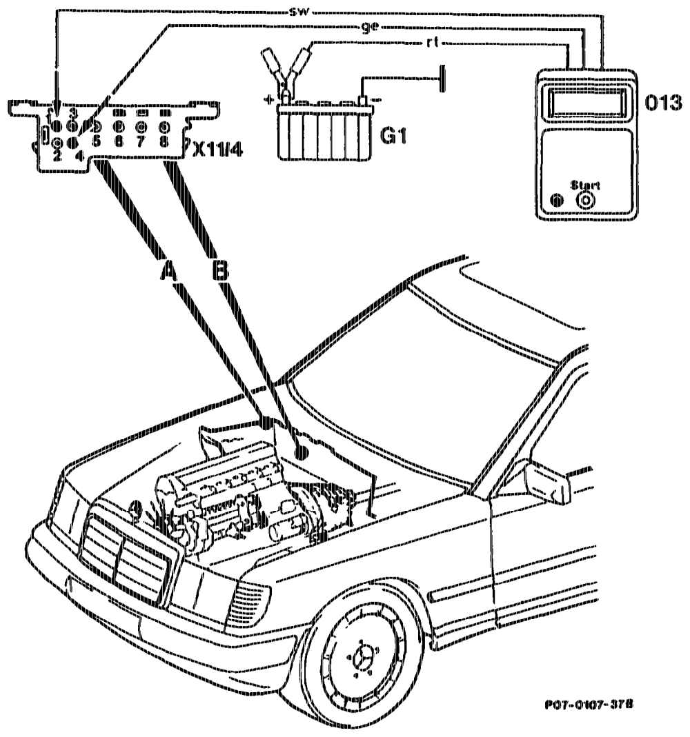
Connection diagram
013 Pulse counter G1 Battery X11/4 = Test connector for diagnostics
A Model 124 B Model 126
Assignment (11/4)
1 Ground
2 TD signal
3 Pulse output Exhaust test signal (only for production tuning)
4 Pulse readout, control unit (EDS)
Notes regarding pulse readout tf a complaint is received but no fault is indicated on the pulse readout, perform the function test, section „7.4”, The number 1 indicates no fautt detected in the electronic system. All other numbers are a ed to a particular fault group. The numbers from 1 to 11 appear on the display panel of the pulse counter. lf the LED U-Batt appears after connecting, pulse counter and power supply for pulse counter are in order.
ytiie RA O7.1.1042-1120/83
Testing Erasing fault memory
1 Connect pulse counter as shown in the After a fault has been rectified, the pulse display connection diagram. must be erased as follows:
9 Operate start button and read out the
Note LED U-Batt in display panel must light up; if not: rectified fault, then press start button for a) test fuse of pulse counter. 6–8 seconds. b) test jack 1 of test connector (11/4) to battery positive (11–14 V).
Note c) test jack 4 of test connector (X11/4) to Each display pulse must be erased jack 1 (6–12 V). Individually. The fault is eliminated and erased when the
2 Engine idling. fault code no longer appears on the fault display.
3 Operate start button for between 2 and 4 Display of a number larger than 1, further faults seconds. in system.
4 Take readout of pulse output and note. Display ”1” = no fault Greater than „1” = — fault in system
5 Again press start button for between 2 and 4 seconds. If no further fault exists in system, the previous readout appears once again.
6 Repeat until the first fault is diplayed again.
7 ~ Rectify noted faults (pulse readout) according to trouble-shooting schedule.
8 Perform cornponent test.
atin = RA 07.1.1042-1120/84
¢) Troubleshooting schedule
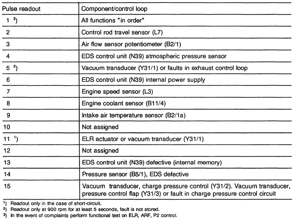
Engine 602.962 The number of pulses indicates whether and which component is faulty and whether components in the control circuit are faulty.
authim = RA 07.1.1042-1120/85
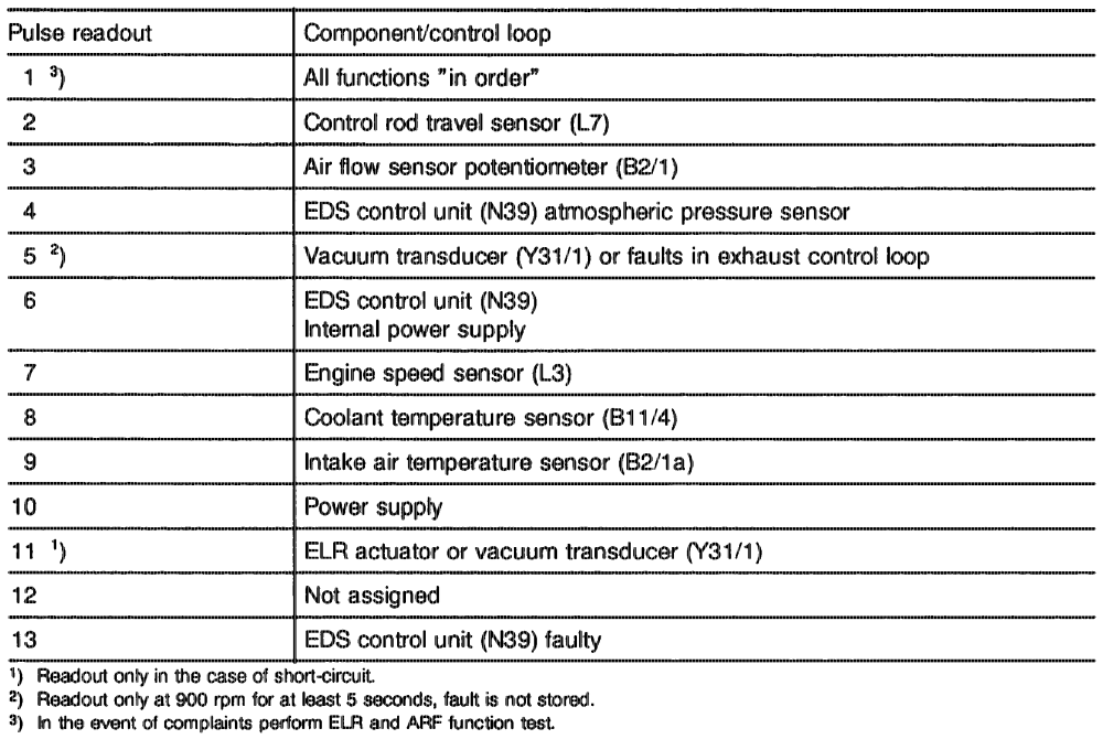
Engine 603.970 The number of pulses indicates whether and which component is faulty and whether components in the control circuit are faulty.
ogtthipn = RA 07.1.1042-1120/86 d) Test program with contact box (Engine 602.962)
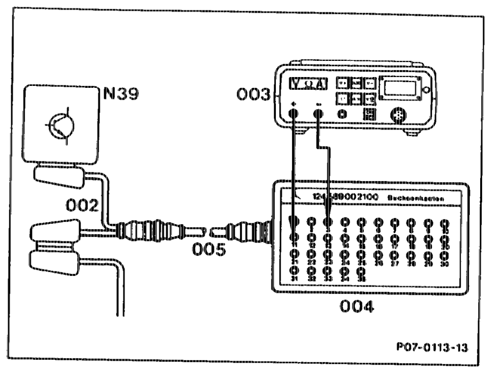
Connection diagram contact box
002 25-pin test cable 124 589 33 63 00 003 Multimeter 004 35-pin contact box 124 589 00 21 00 005 Test cable 124 589 34 63 00 N39 EDS control unit
Symbols for test Instruments
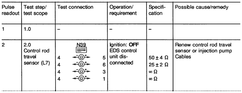
SgRaE Contact box Y)> Voltage measurement (volt, direct Multimeter voltage) —{ Jack Resistance measurement (ohms) 0m Pin
ghhiy = RA 07.1.1042-1120/87
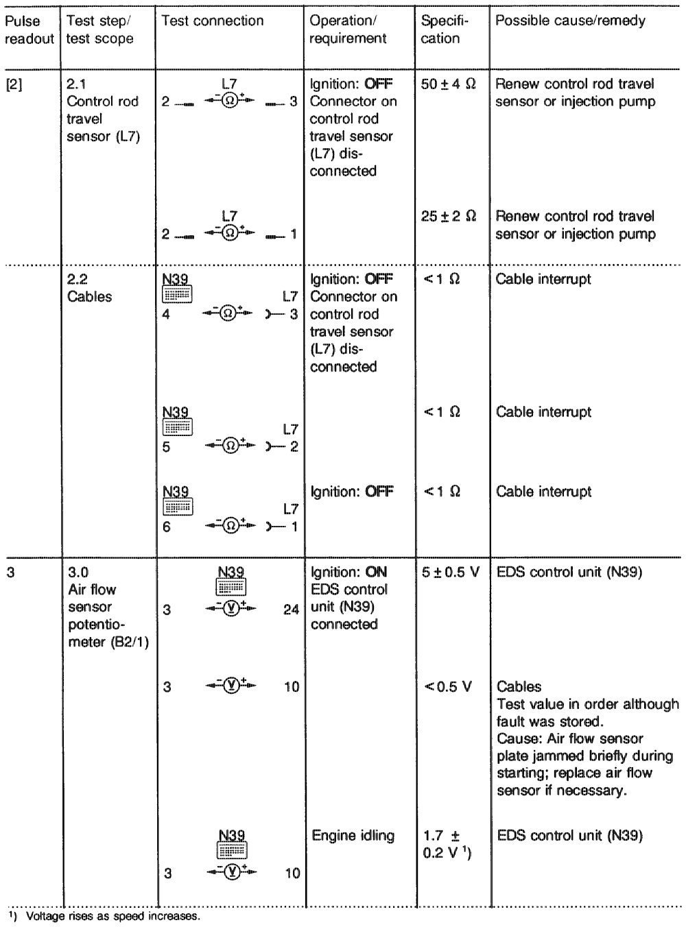
otiign = RA 07.1.1042-1120/88
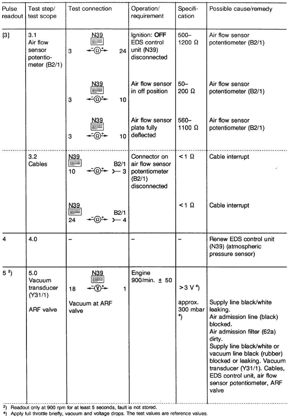
qth = RA 07.1.1042-~1120/89
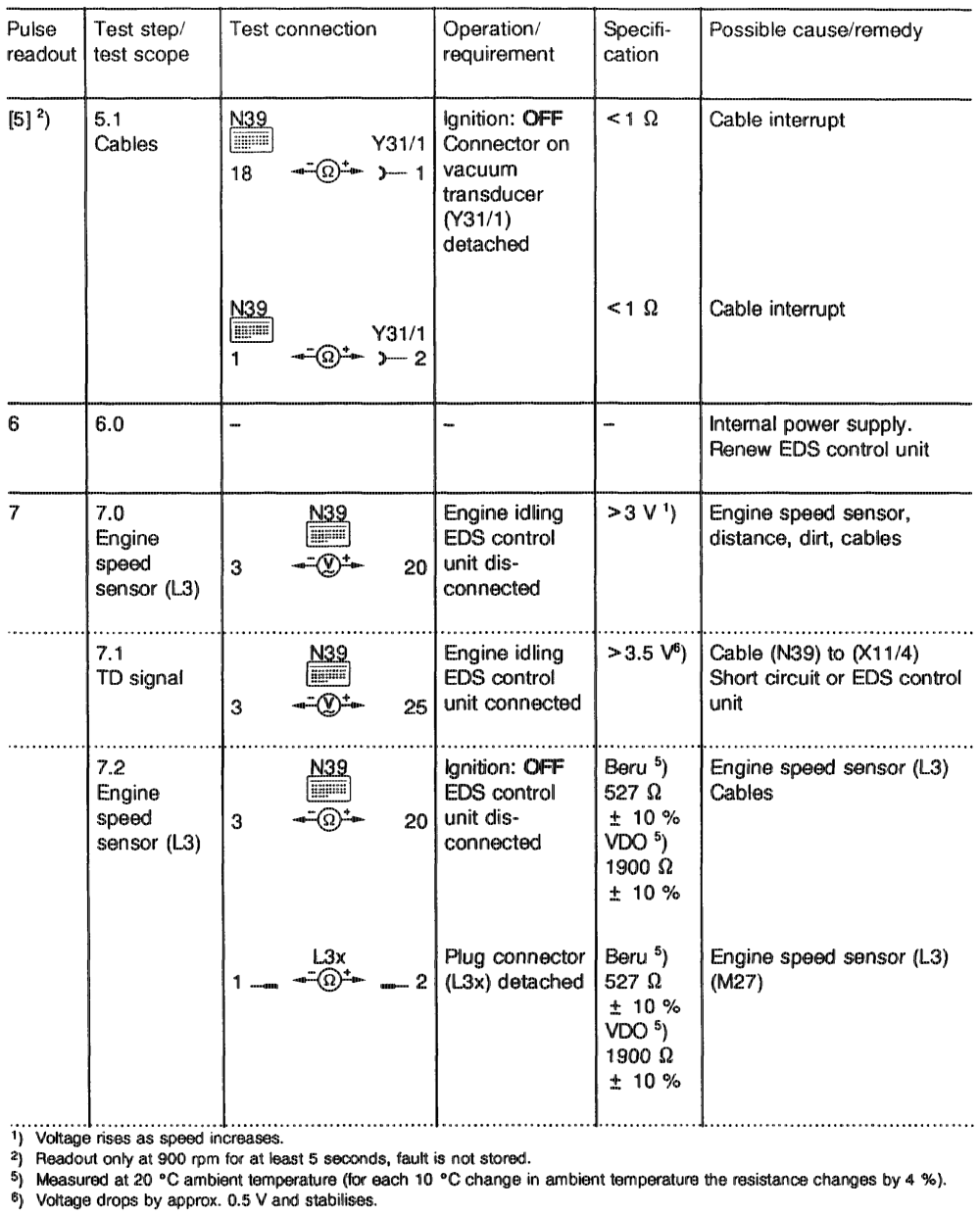
aptiie = RA 07.1.1042-1120/90
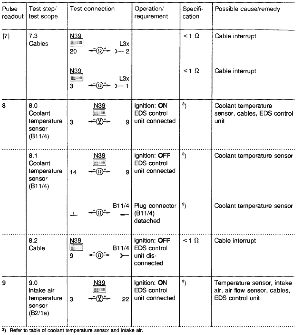
aptiye = RA 07.1.1042-1120/91
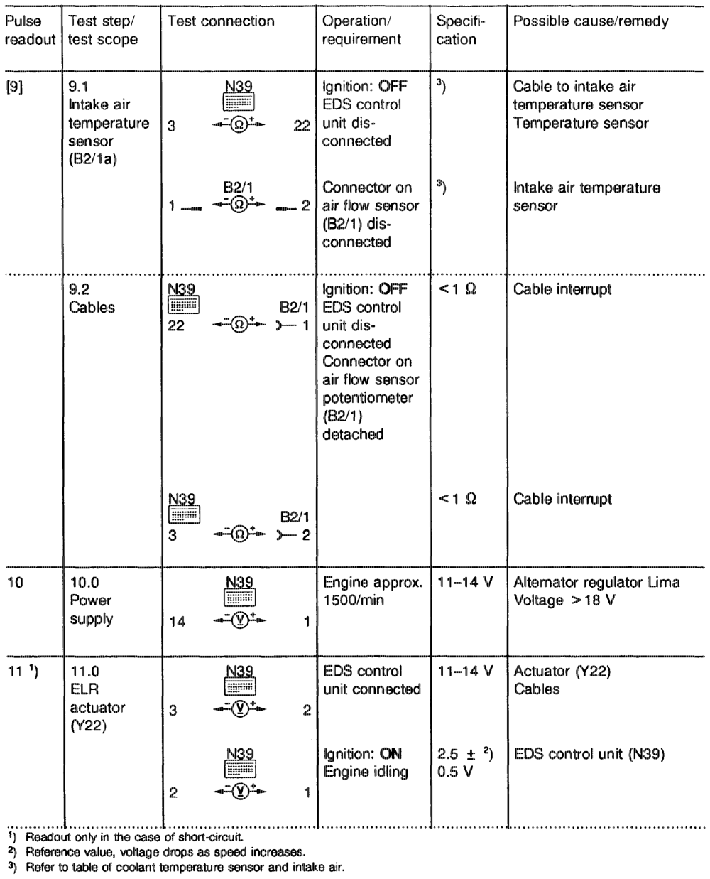
aptiiiyn = RA 07.1.1042-1120/92
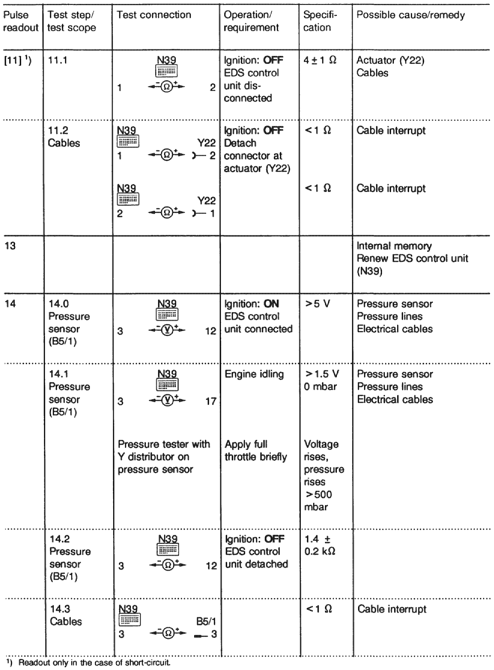
utiie = RA 07.1.1042-1120/93
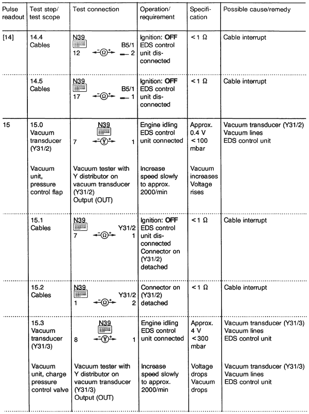
aptiin = RA 07.1.1042-1120/94
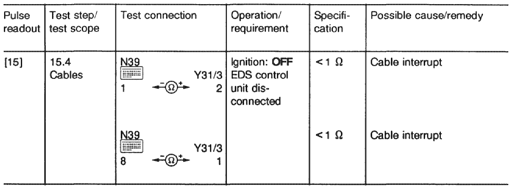
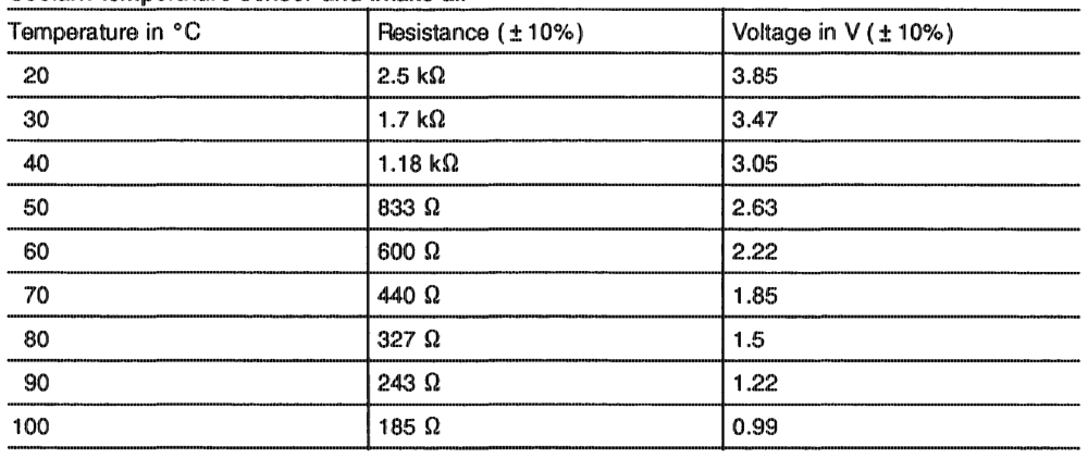
Coolant temperature sensor and intake air
ptihije = RA O7.1.1042~1120/95 e) ELR, ARF function tests, P2 control, Engine 602.962
Note
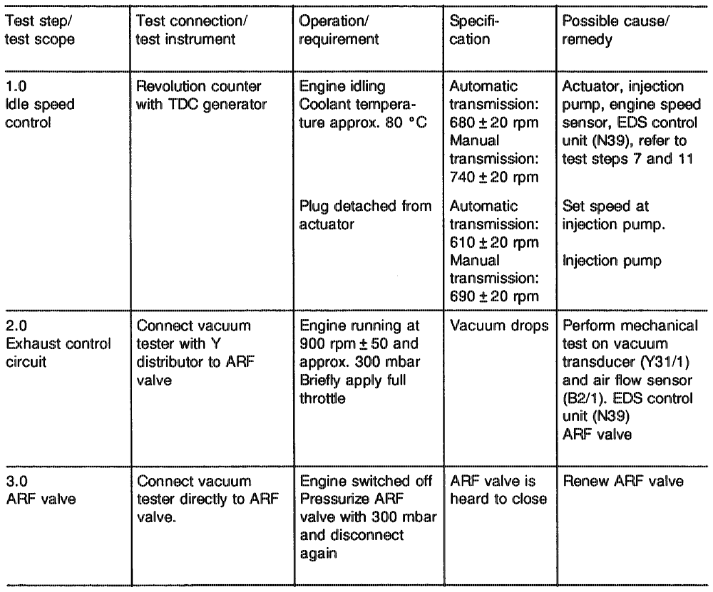
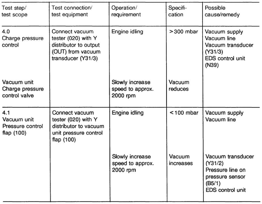
This test is to be performed when in the event of complaint concerning the pulse readout, no fault is displayed
apthim = RA 07.1.1054—-1120/96
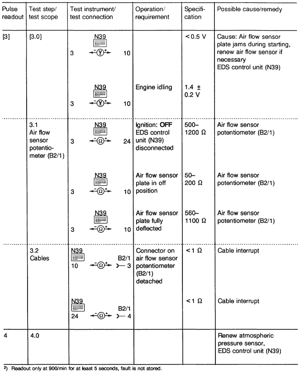
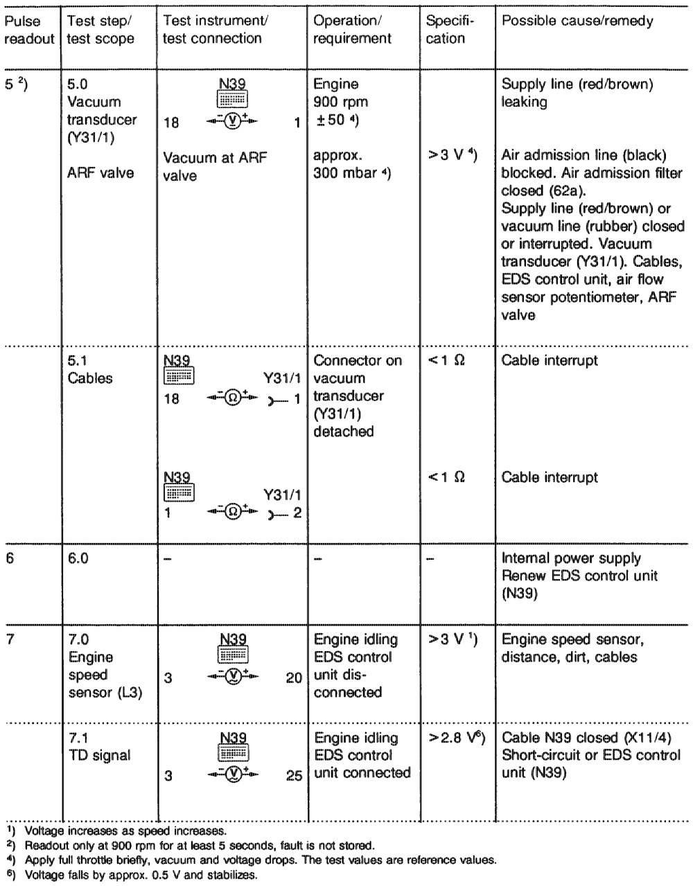
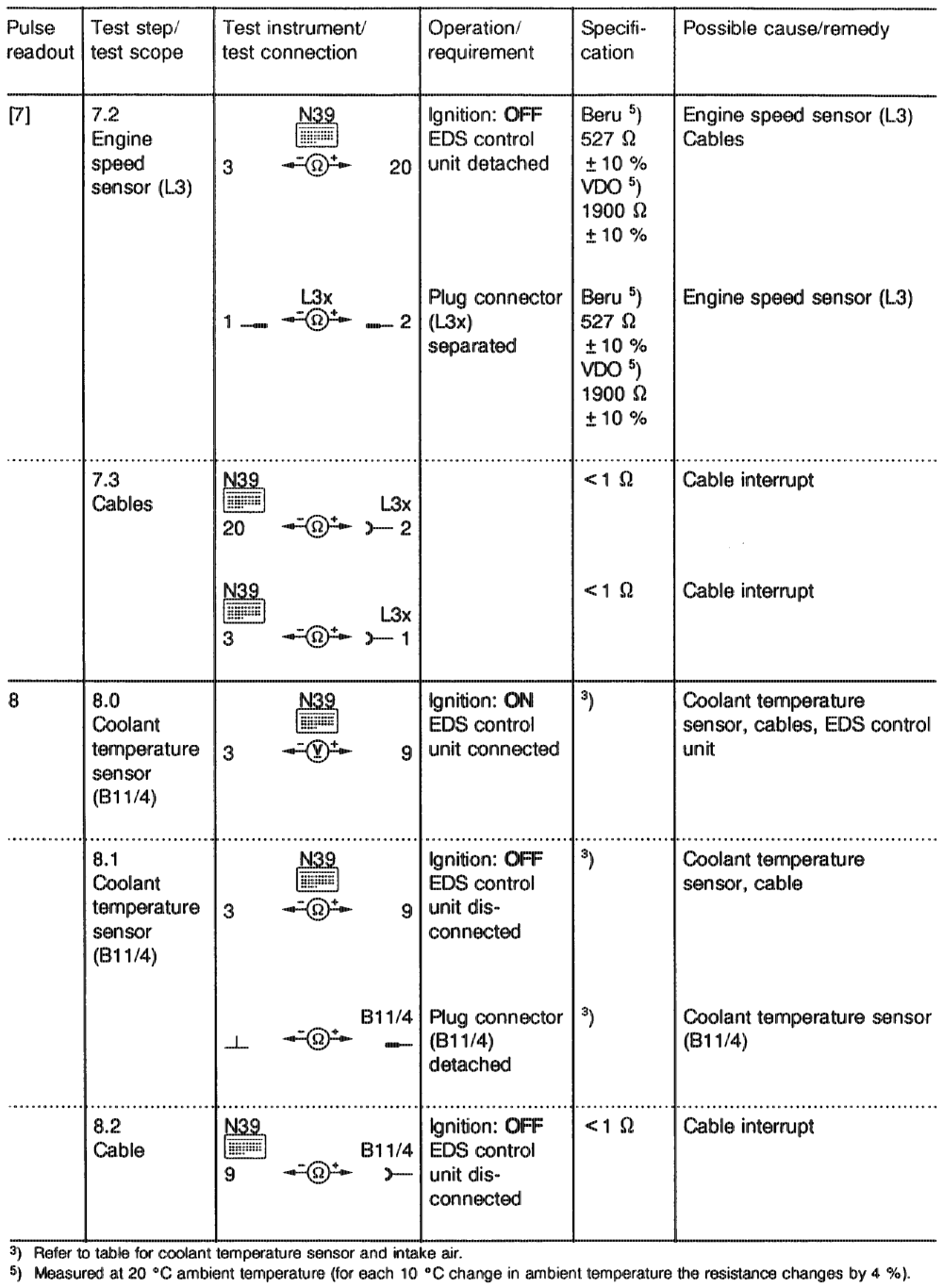
aptiiayn = RA 07.1.1042~1120/97 f) Test program with contact box (Engine 603.970)
Symbols for test instruments:
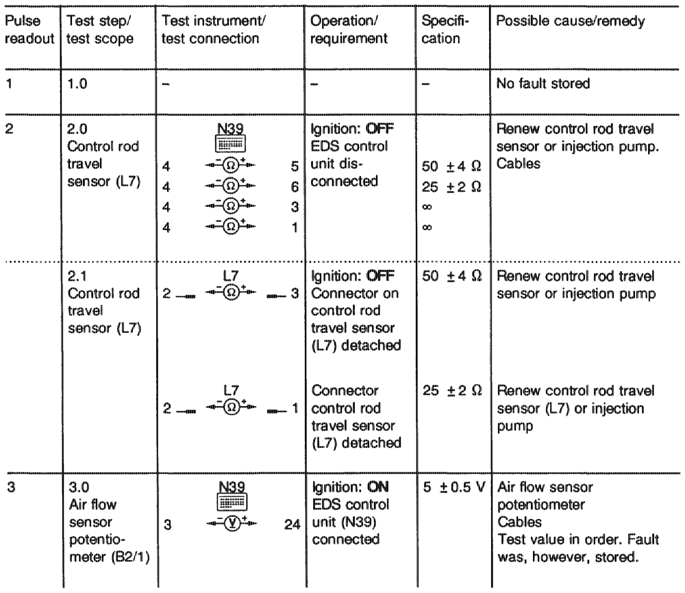
Contact box te Voltage measurement (volt, direct Multimeter voltage) —¢ Jack -“@*= Resistance measurement (ohm) an Pin
eotiign = RA 07,1.1042–1120/98
oti = RA Q7.1.1042-1120/99
aptihiyn = RA 07. 1.1042-1120/100
egtiayn = RA 07.1.1042-1120/101
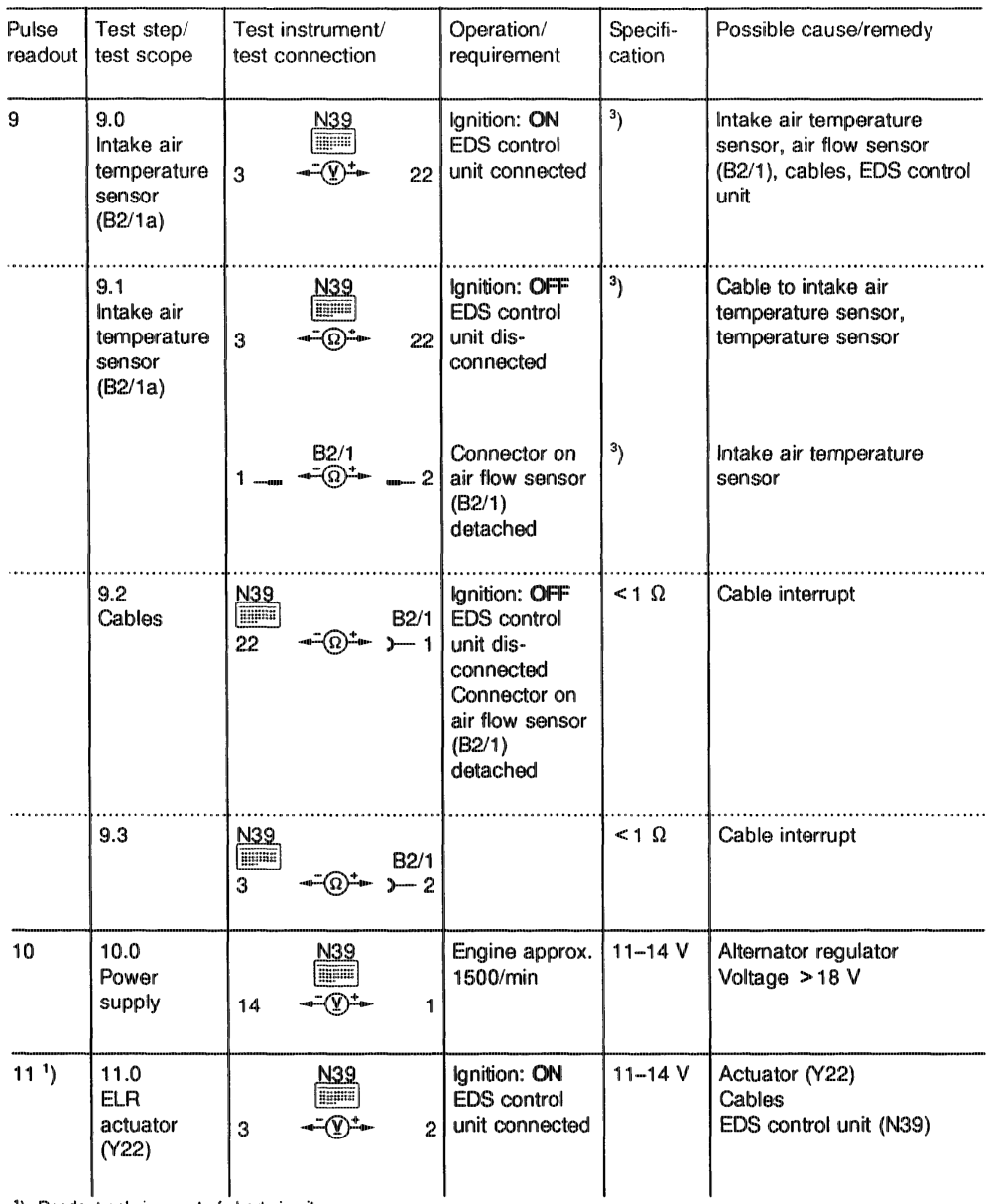
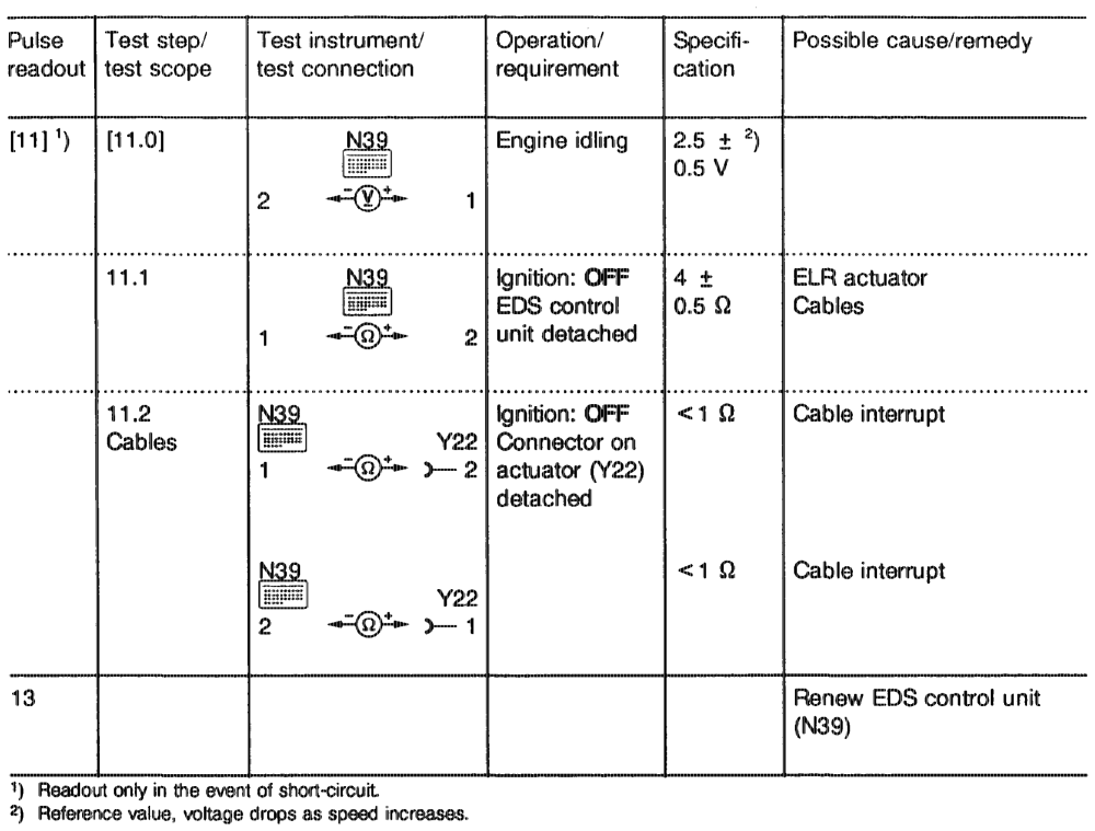
1) Readout only in event of short-circuit. 2) Reference value, voltage drops as speed increases. 3) Refer to table for coolant temperature sensor and intake air.
ptiian = RA 07.1.1042~1120/102
pti = RA 07.1.1042-1120/103
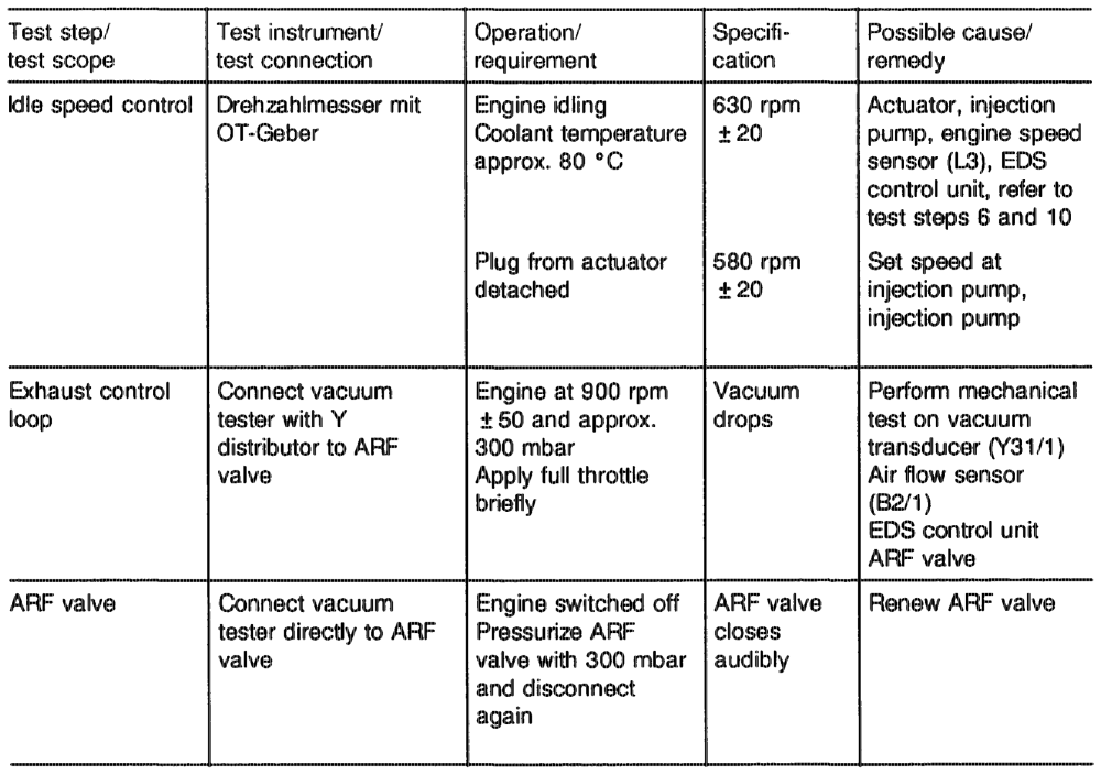
g) ELR and ARF function test (Engine 603.970)
egtiiiym = RA Q7.1.1054-1120/104
. Engines 602.96 and 603.96, Models 124 and 201 Basic Version Code 62/0 as of 06/91 CAD EG) CH G) as of Model Year 1992
Short-test, engine 602.96, 603.96 b) Testing with pulse counter c) Troubleshooting schedule Test program with contact box, engine d) 602.96 Test program, anti-jerk control (ARA), @) engine 602.96 with manual transmission f) ELR, ARF function test, P2 control, ARA, engine 602.96 )) Test program with contact box, engine 603.96 h) ELR, ARF function test, engine 603.96 Test program for components not covered with pulse readout, engines 602.96, 603.96
apie = RA 07.1.1042-1120/105
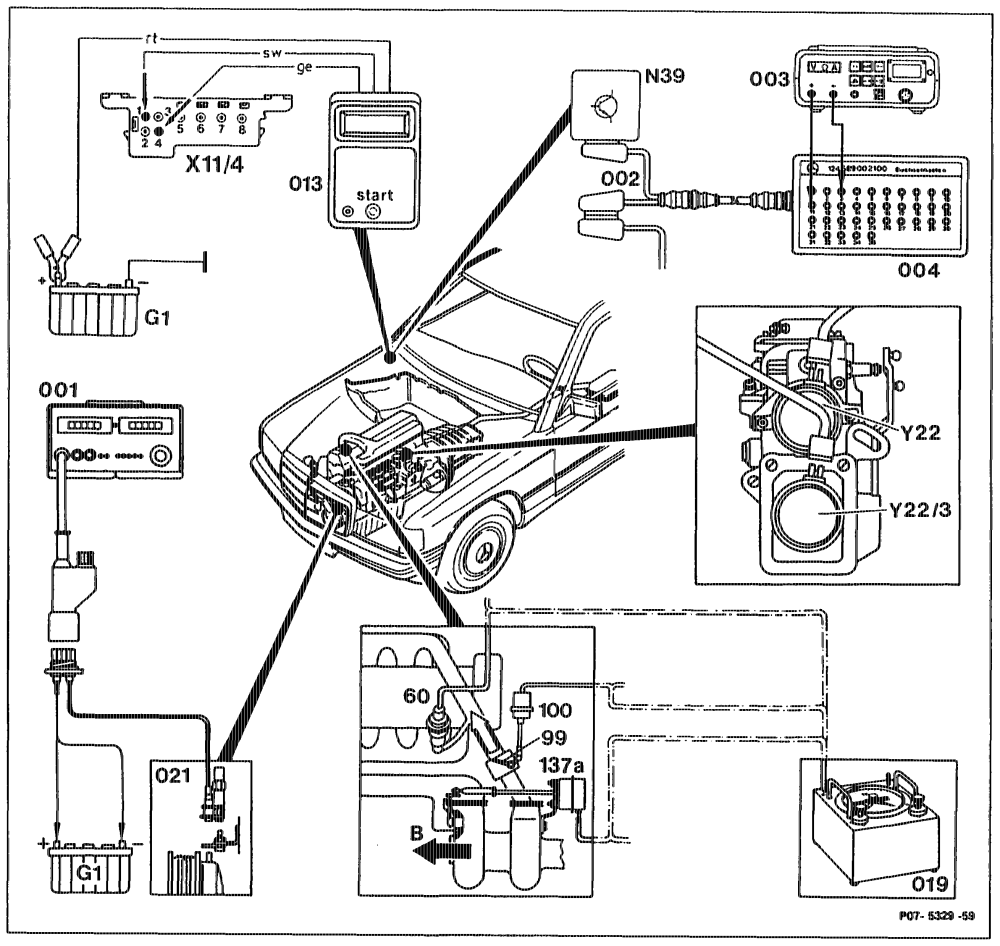
a) Short-test, engine 602.96, 603.96
pin = RA O7.1,1042-1120/106
Digital tester (001) and pulse counter (021) ….. connect, disconnect. connect to battery (G1) and to test coupling Pulse counter (013) 6… eee eee (X11/4), disconnect.
Contact box (004) with test cable (002) …….. connect to EDS control unit (N39), disconnect.
Digital multimeter (003) «0.2… 6… eee ee eee connect to contact box (004), disconnect.
connect with Y distributor to ARF valve or to Vacuum tester (019) 2… ee eee eee vacuum unit, charge pressure control and vacuum unit, vacuum control flap, disconnect. Fuse at overvoltage protection relay (K1/1) ….. check. Selector lever 2.0… ee eee eee move into position „P”. Air conditioner/automatic climate control ……. switch off.
Battery voltage at overvoltage protection, test (specification 12 V). contacts Tand5 «6… cece eee eee eee warm up to operating temperature (coolant temperature approx. 80 °C). press for 2–4 seconds. read and note. Display 2… cee eee eee press once again; if no new display appears, no further fault in system.
The number which appears in the display field of the pulse readout indicates whether and which component is faulty or whether components in the control loop are faulty. See fault table saction c).
aptiinje = RA 07.1,1042-1120/107 b) Testing with pulse counter
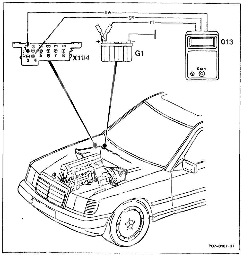
Connection diagram
013 Pulse counter G1 Battery 11/4 Test coupling for diagnosis
Contact assignment 0411/4)
1 Ground
2 TD signal
3 Pulse output, ARA control unit (N8/2) (only manual transmission)
4 Pulse output, EDS control unit
apis RA 07.1.1042-1120/108
Notes regarding pulse readout § Once again press start button for between 2 If no fault is displayed via the pulse output even and 4 seconds. If no further fault is stored in the though a complaint exists, perform the function system, the previous readout appears once test, section „f” (engine 602.96) or section ”h” again. ff there is a further fault in the system, its (engine 603.96). fault code is displayed.
The figure 1 indicates no fault stored in the 6 Repeat this procedure until the first fault is electronic system. All other figures are assigned again displayed. to a particular component/fault group. 7 Rectify noted faults (pulse output) as stated The figures from 1 to 15 appear in the display in the troubleshooting schedule. field of the pulse counter. If the U-Batt LED lights up after connecting the 8 Perform components test. pulse counter, the pulse counter and voltage supply of the pulse counter are in order. Eré fault memory After a fault has been rectified, the pulse Testing with pulse counter displayed must be erased as follows:
1 Connect pulse counter as specified in the 9 Pr start button and read the rectified connection diagram. fault, then press start button for 6-8 seconds.
Note U-Batt LED in the display field must light up; if
Note Each fault displayed must be erased not: a) Check fuse of pulse counter. Individually. b) Test contact 1 of test coupling 0411/4) to Once the fault has been rectified and erased, battery positive (11–14 V). the fault code no longer appears in the fault c) Test contact 4 of test coupling (<11/4) to output. contact 1 (6–12 V). lf a figure greater than 1 is displayed, further faults exist in the system.
2 Engine idling If the fault memory is read with the pulse counter with ignition „ON”, the pulse readout ”7” (engine speed sensor) appears.
3. ~=Press start button for between 2 and 4 seconds.
4 Read off pulse output display and note. Display „1” = no fault stored. Greater than 1” fault in system.
aptiiajy = RA 07.1.1042-1120/109 c) Troubleshooting tables
The number of pulses in the display indicates whether and which components are faulty and whether components in the control circuit are faulty.
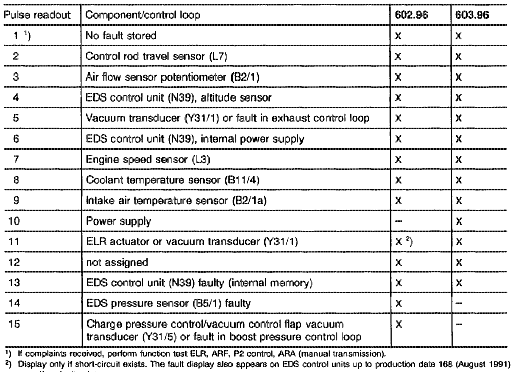
EDS contro! unit
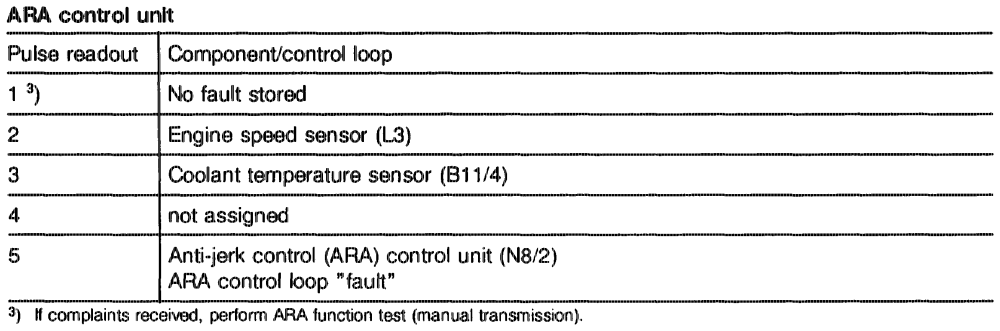
even if no fault exists.
pti = RA 07.4.1042-1120/110 d) Test program with contact box, engine 602.96
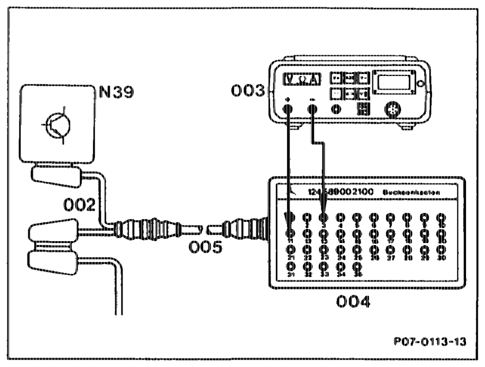
Contact box connection diagram
002 25-pin test cable 124 589 33 63 00 003 Multimeter 004 35-pin contact box 124 589 00 21 00 005 Test cable 124 589 34 63 00 N39 EDS control unit
Symbols for test Instruments Contact box Voltage measurement Multimeter (volts, DC voltage) Contact Resistance measurement (ohms) _ Pin
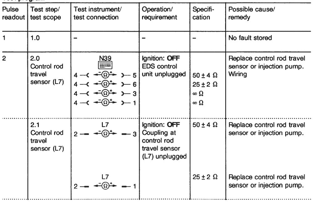
Test program
egtiin = RA 07.1.1042-1120/111
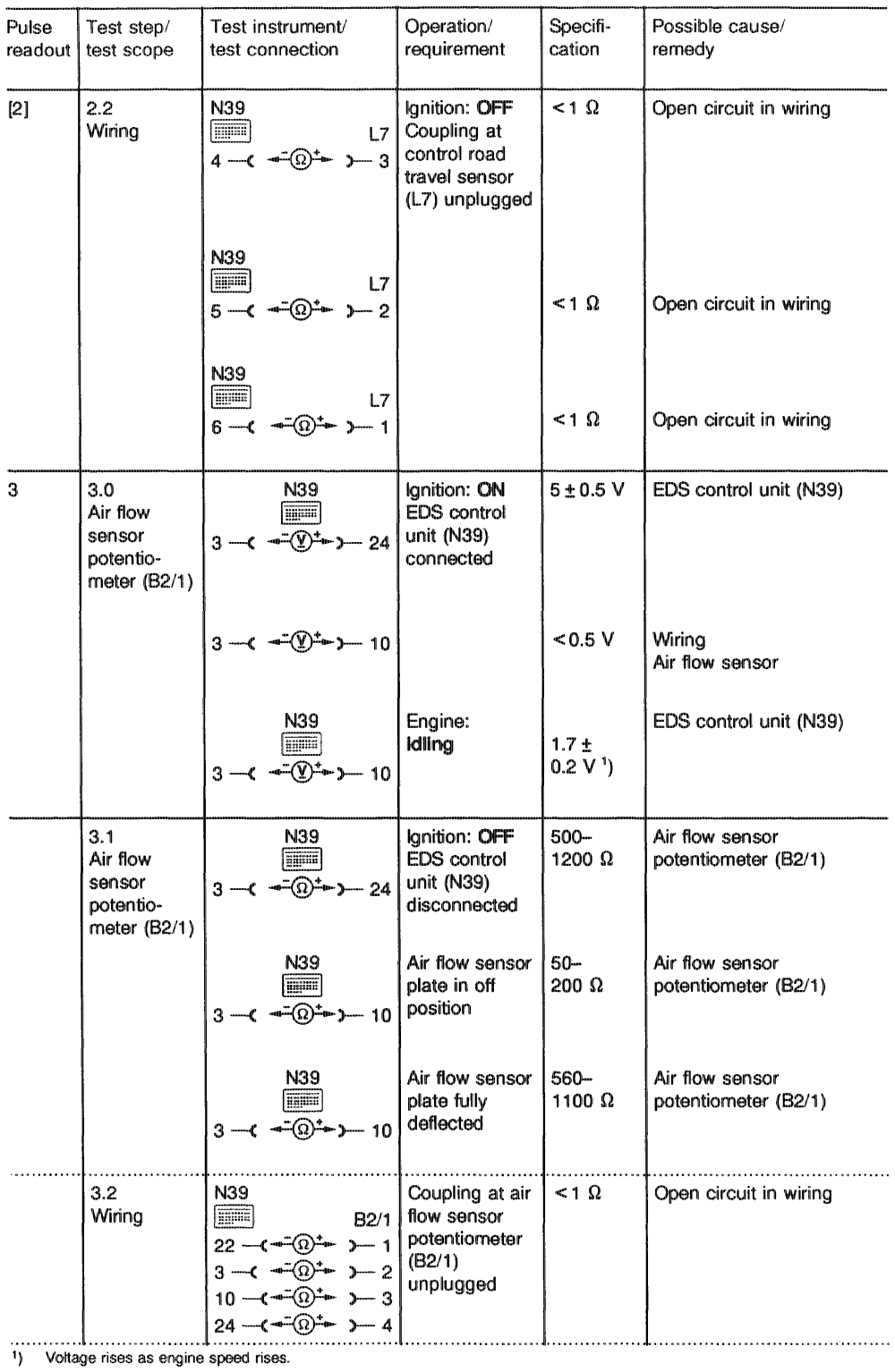
eutthiyn = RA 07.1.1042-1120/112
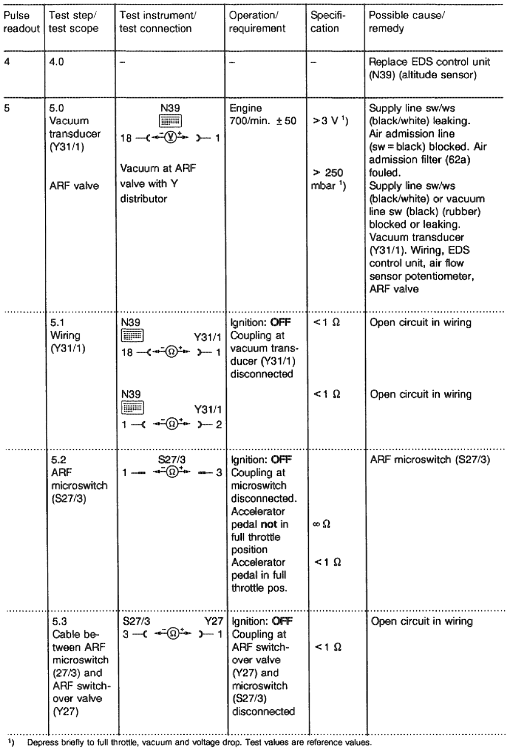
gti = RA 07.1.1042-1120/113
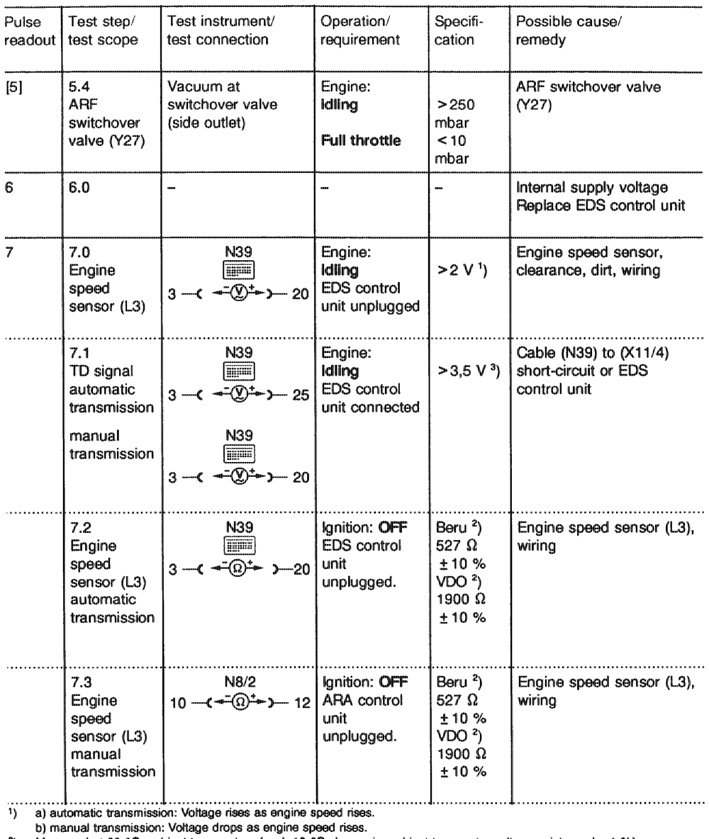
2) Measured at 20 °C ambient temperature (each 10 °C change in ambient temperature alters resistance by 4 %). 3) Voltage drops as engine speed rises.
otis = RA 07.1.1042-1120/114
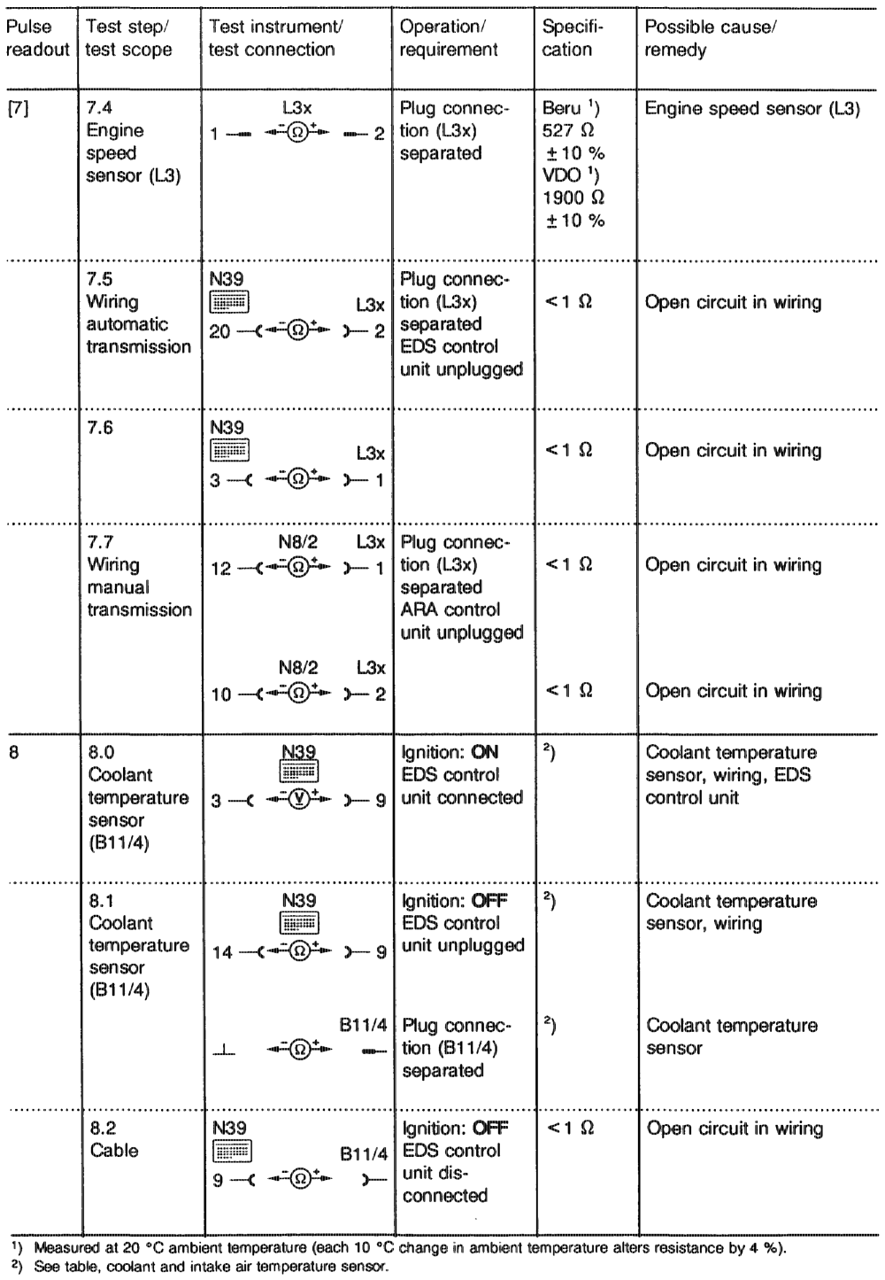
ptiiiyn = RA 07.1.1042-1120/115
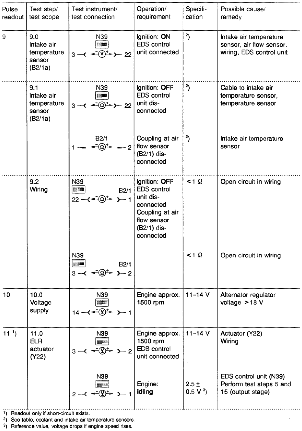
ptinn = RA 07.1.1042-1120/116
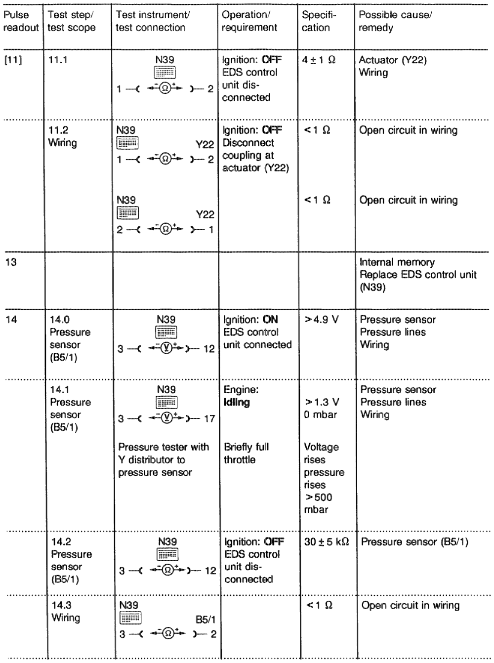
eptitiyn = RA 07,1.1042-1120/117
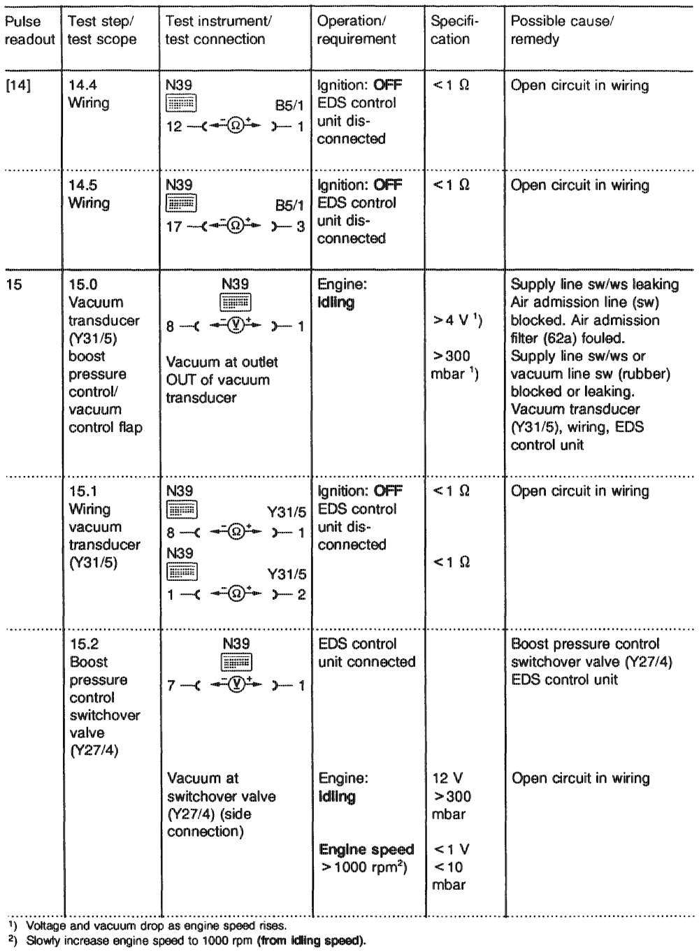
gts = RA 07.1.1042~1120/118
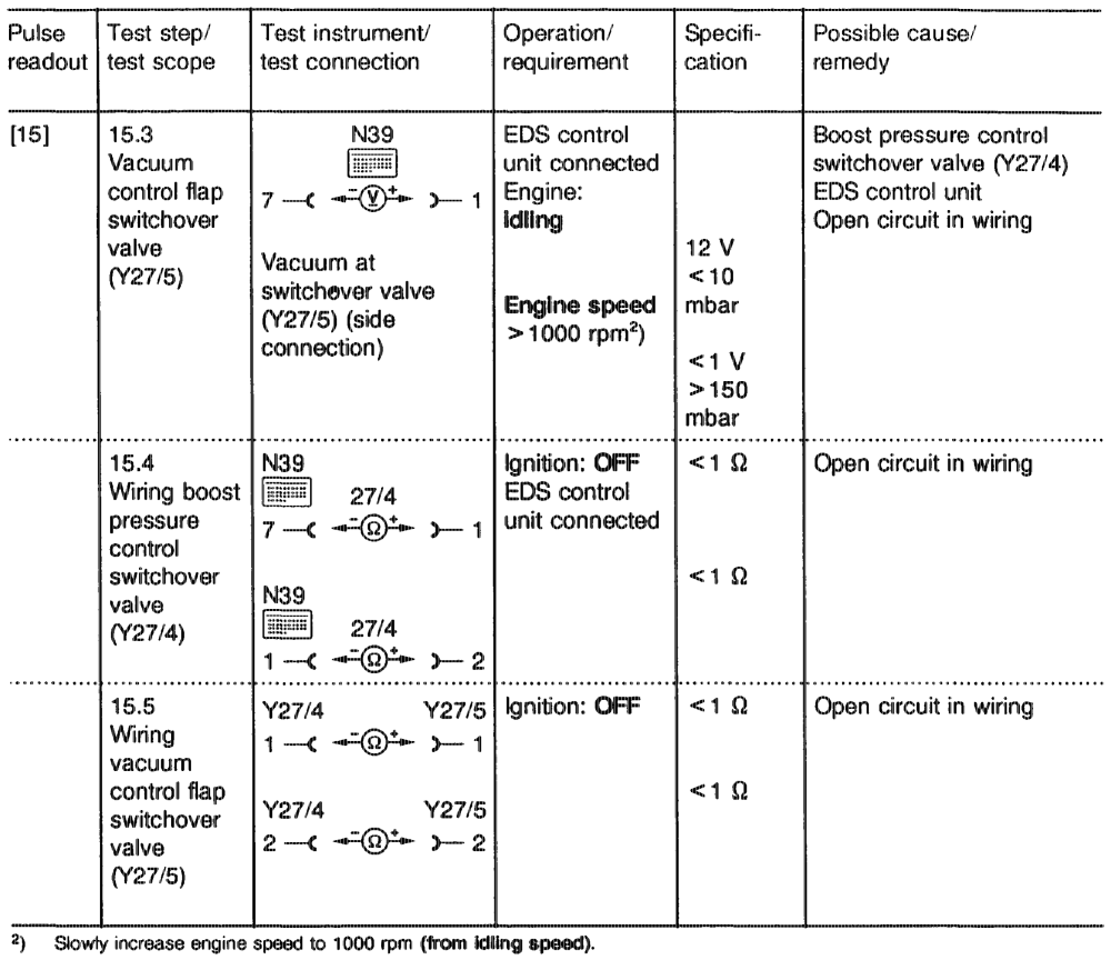
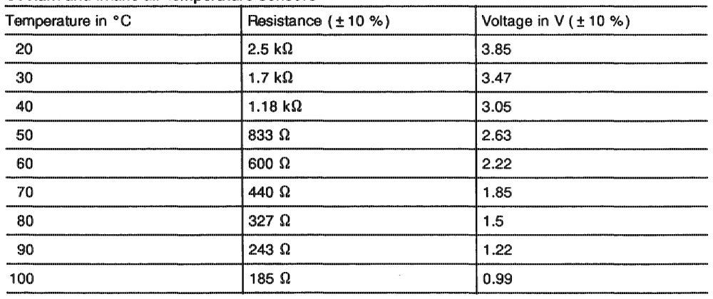
Coolant and intake alr temperature sensors
aptiis = RA 07.1.1042-1120/119
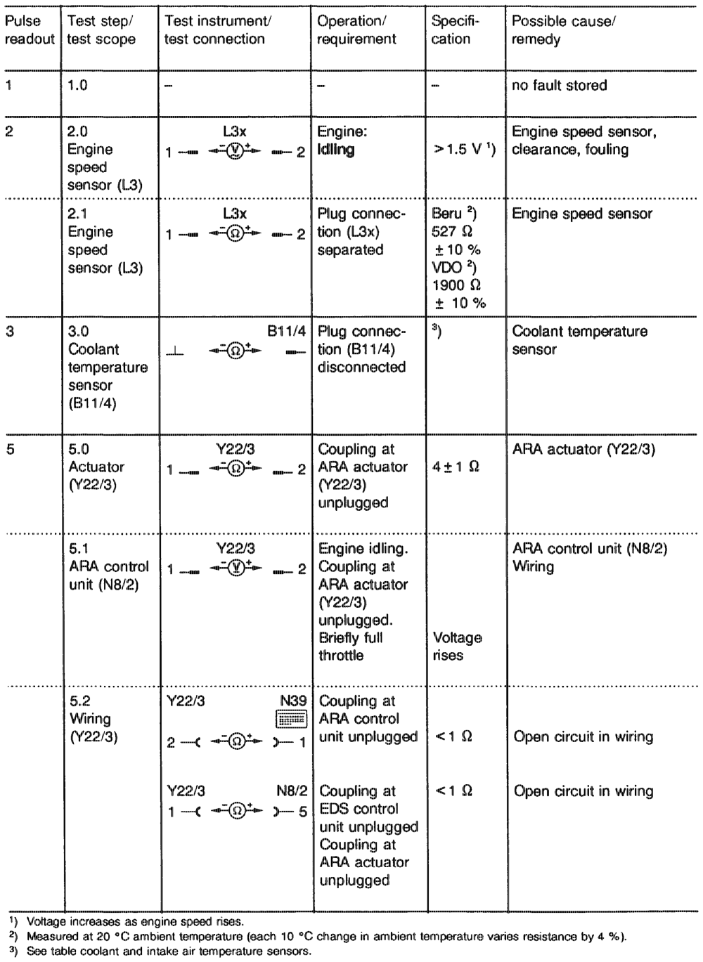
e) Test program anti-jerk control (ARA), engine 602.96 with manual transmission
oti = RA 07.1.1042-1120/120 f) Function test ELR, ARF, P2 control, ARA, Engine 602.96 (ARA only with manual transmission)
Note
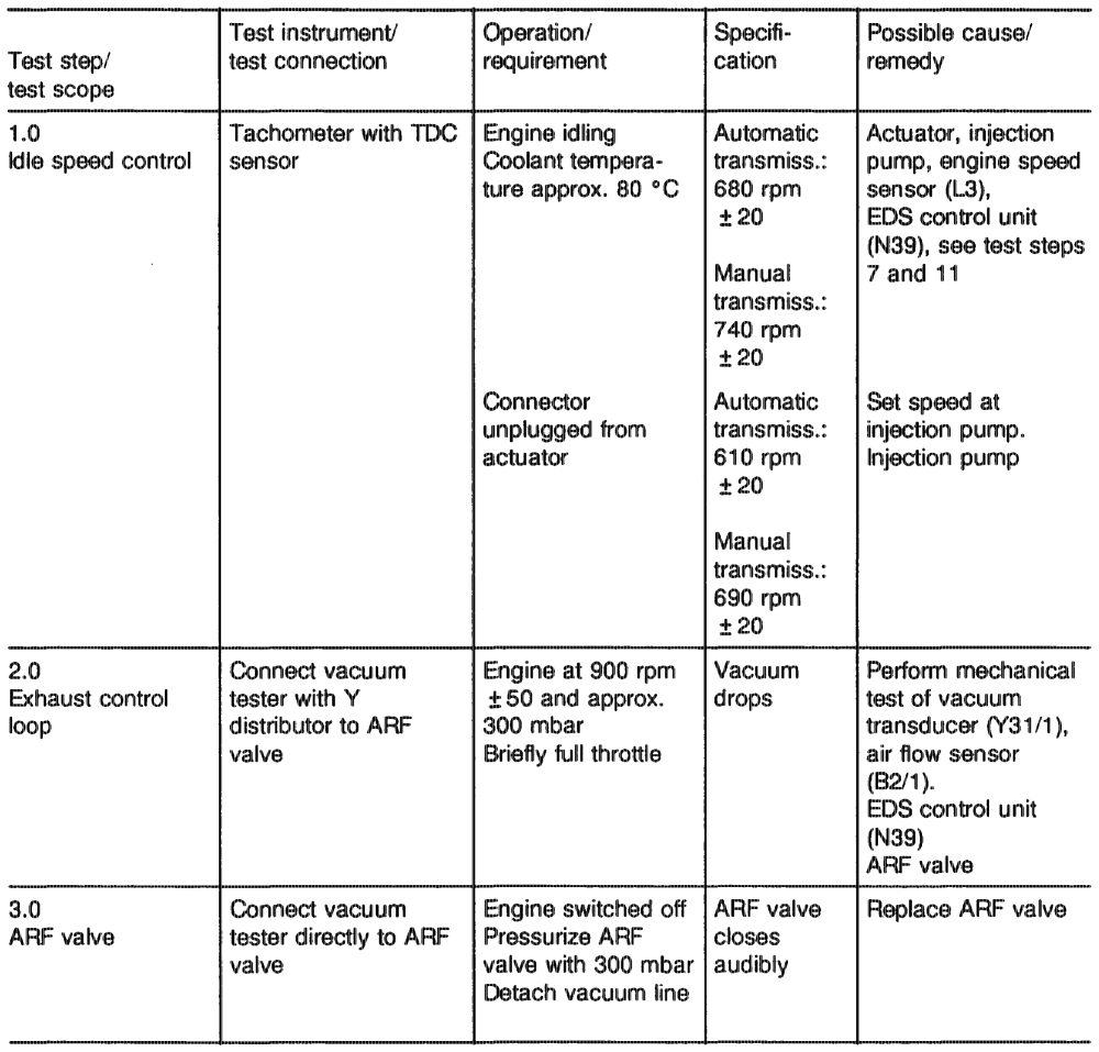
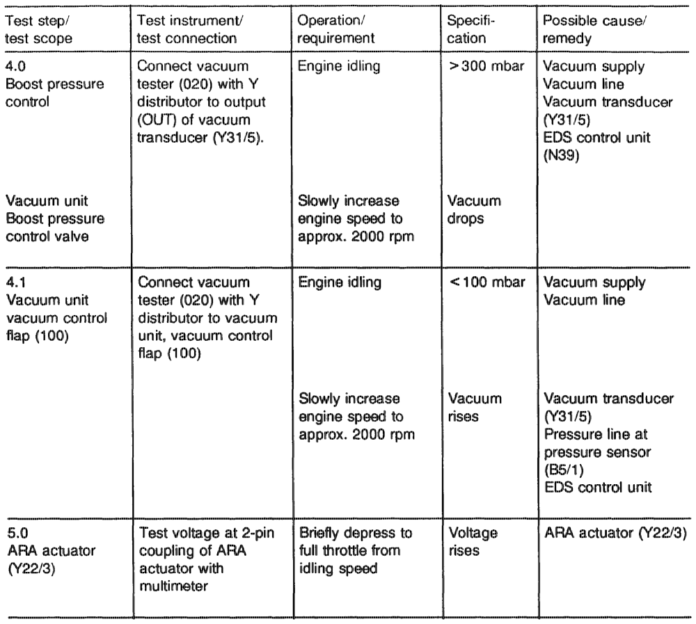
This test should only be performed if a complaint is received but no fault is displayed via the pulse readout.
aptiiiyn = RA 07.1.1054-1120/121
aphitie = RA O7.1.1042-1120/122 g) Test program with contact box, engine 603.96
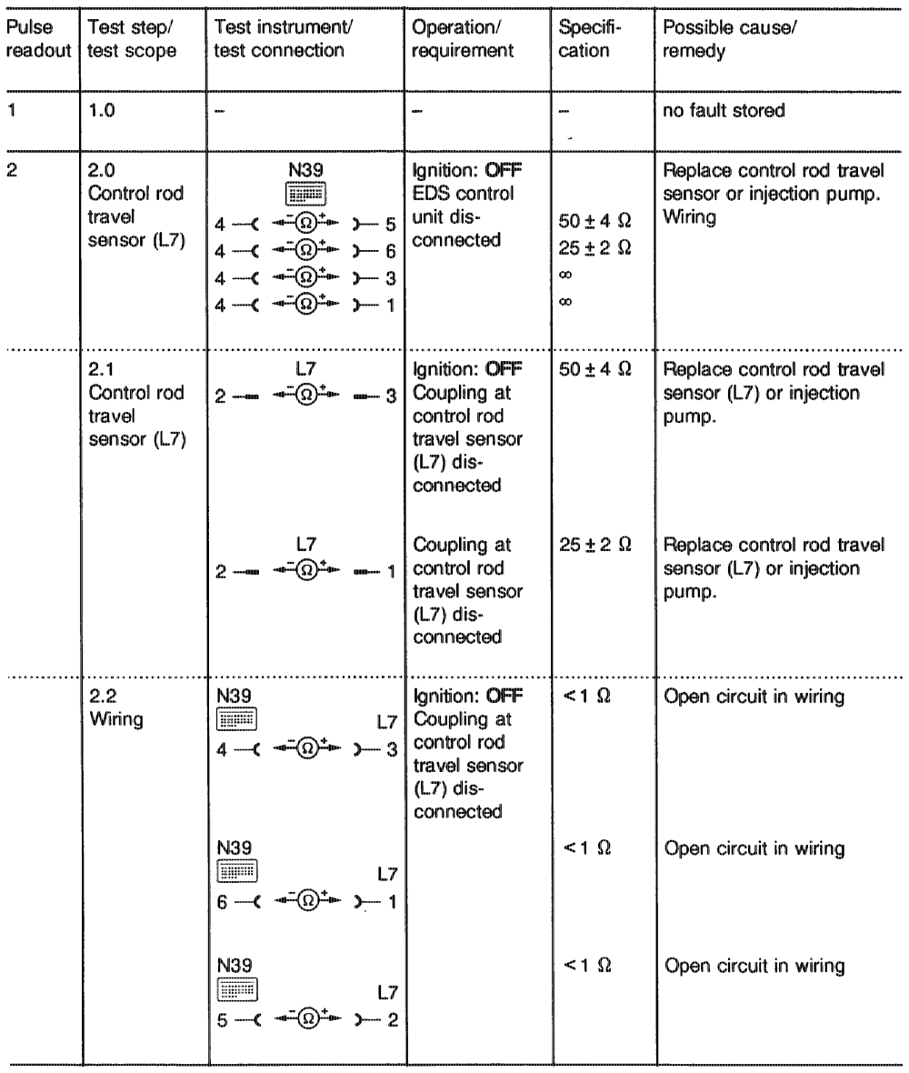
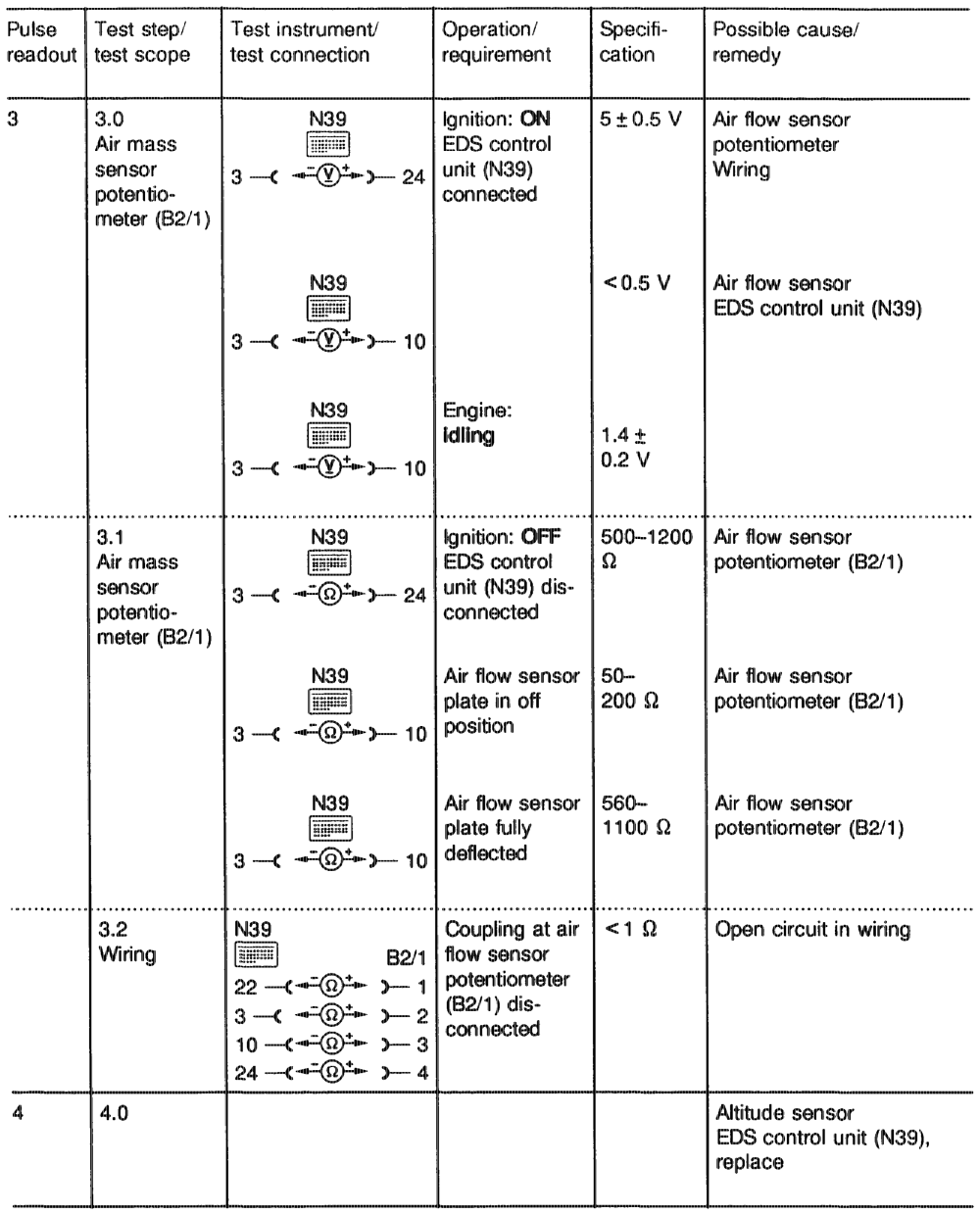
Symbols for test instruments Contact box <=(V)*» Voltage measurement Multimeter (volts, DC voltage) —¢ Contact Resistance measurement (ohms) Pin
gttiajn = RA 07.1.1042-1120/123
tiie RA 07.1.1042-1120/124
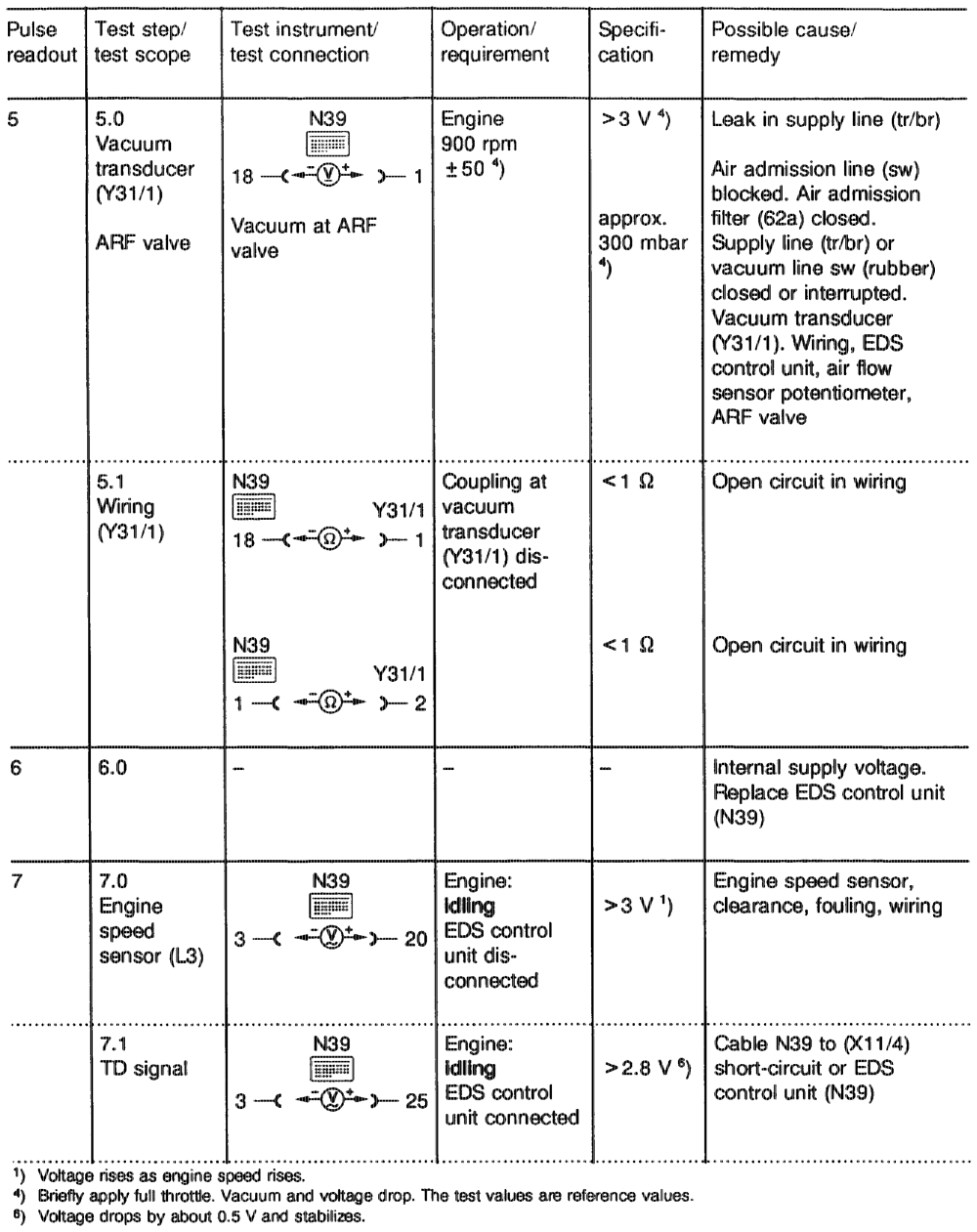
egtihija = RA 07.1.1042~1120/125
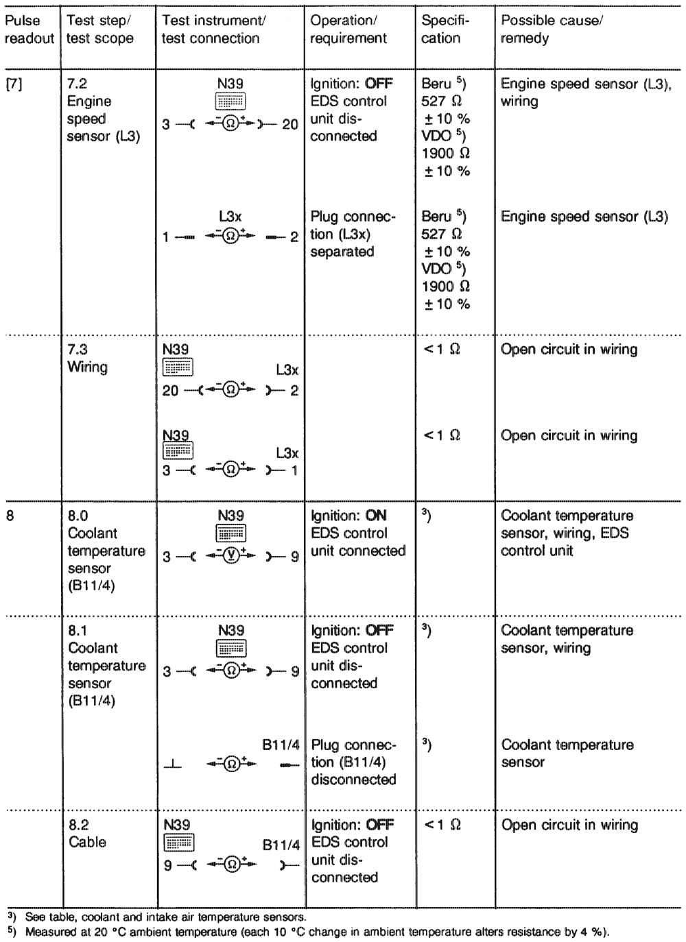
eptiin RA 07.1.1042-1120/126
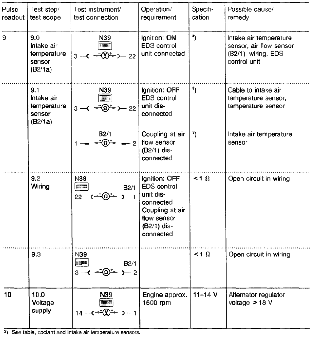
eptihijn = RA O7.1.1042-1120/127
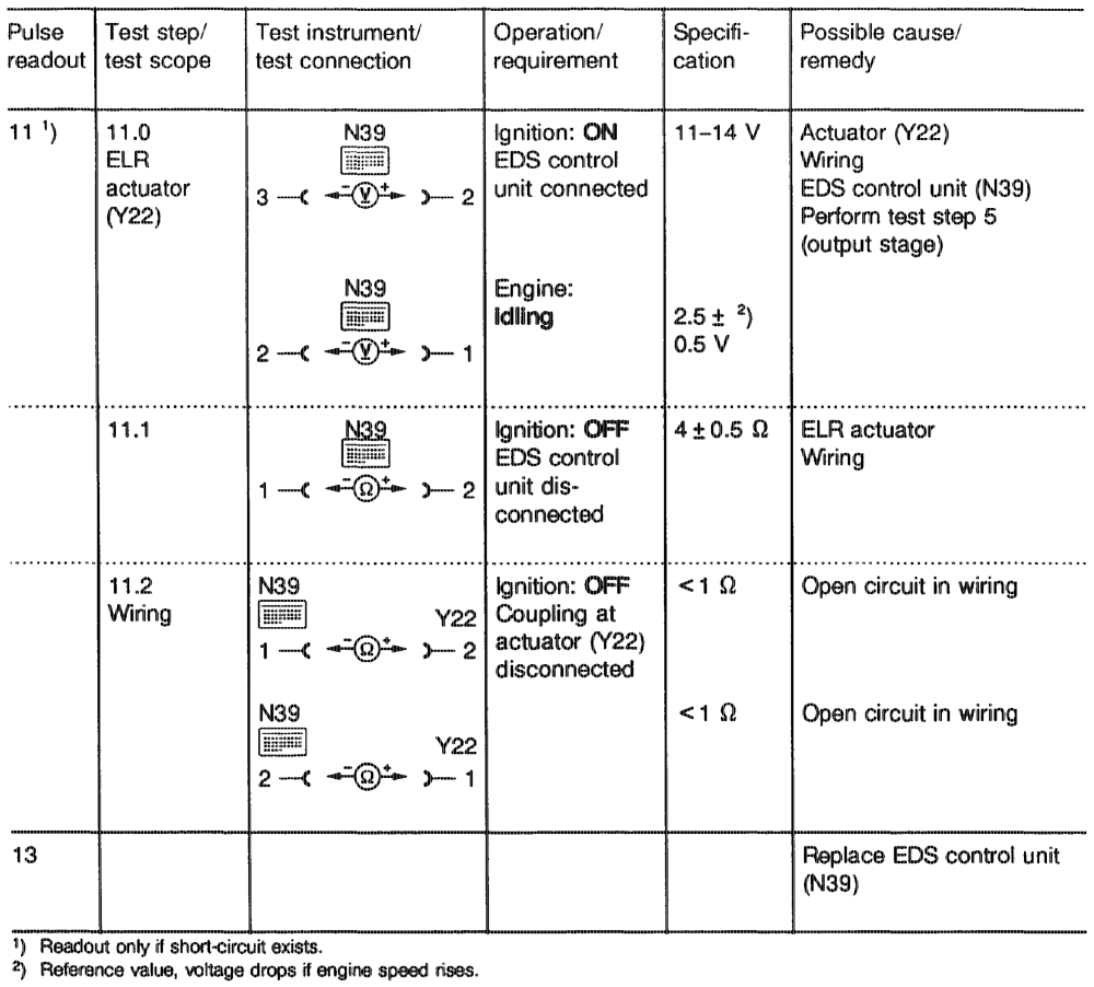
aptiaje = RA 07.1.1042-1120/128
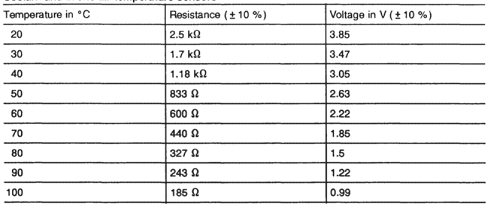
Coolant and intake air temperature sensors
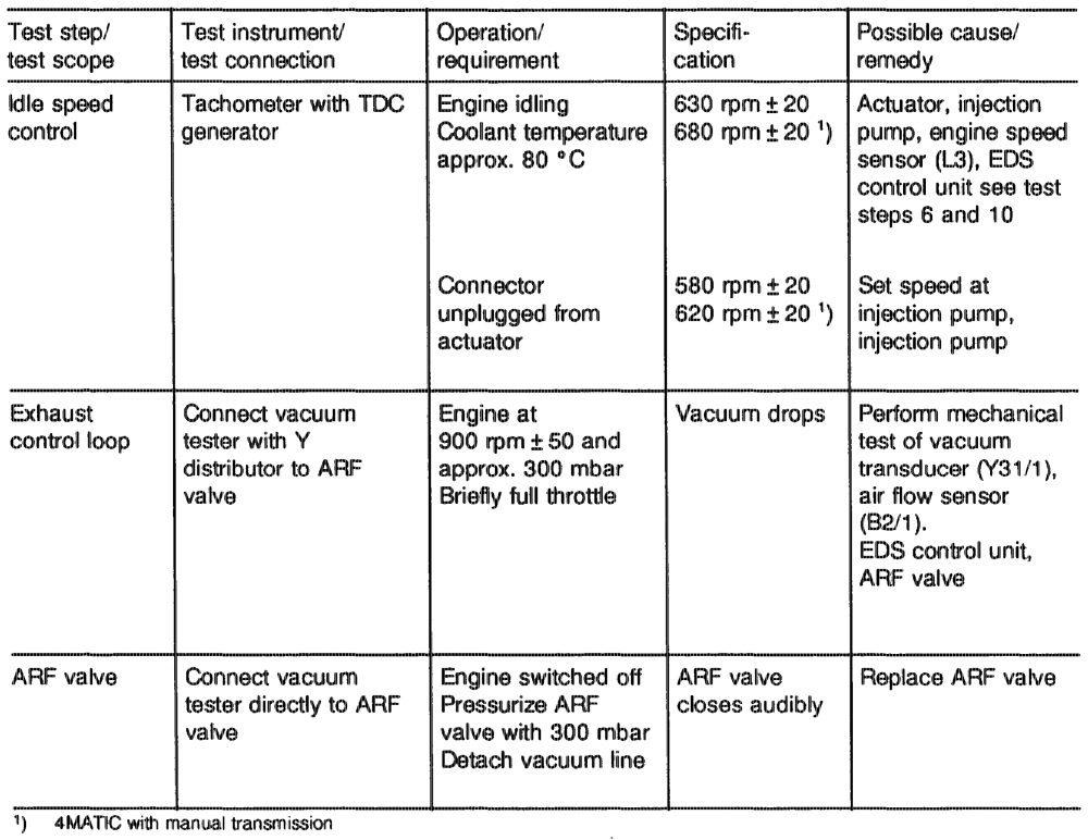
h) Function test ELR, ARF engine 603.96
otis = RA 07.1.1054-1120/129
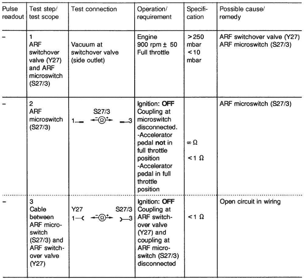
i) Test program for components not covered with pulse readout, engines 602.96, 603.96
phi RA O7.1.1042-1120/130
. Engine 603.971, Model 140 Gs) Model Year 1992
Short-test Tasting with pulse counter Troubleshooting schedule Test program with contact box Test program for components not covered with pulse output f) Function test ELR, ARF, P2 control g) Testing key-operated engine stop
otihin = RA 07.1.1042-1120/131
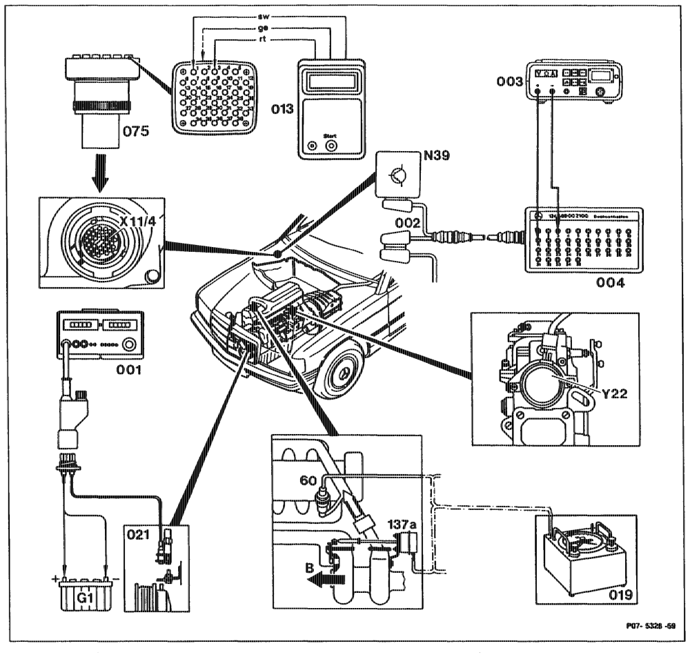
a) Short-test
aghiiiyn = RA 07.1.1042-1120/132
Digital tester (001) and pulse counter (021) ….. connect, disconnect. connect with adapter (075) to test coupling Pulse counter (013) 2… ee ee eee (X11/4), disconnect.
Contact box (004) with test cable (002) …….. connect to EDS control unit (N39), disconnect.
Digital multimeter (003) 2.0… 0. eee eee eee connect to contact box (004), disconnect.
Vacuum tester (019) 2… eee eee ee connect with Y distributor to ARF valve or to boost pressure control vacuum unit, disconnect. Fuse at overvoltage protection (K1/1) ……… check. Selector lever 2… ee eee eee eee move into position ”P”. switch off. warm up to operating temperature (coolant temperature approx. 80 °C) check (read pulse output base module contact 8), see Diagnosis Manual Chassis Volume 1.
Note Before reading the stored faults via the pulse output, the battery must on no account be disconnected, base module and EDS control unit (N39) must on no account be unplugged.
Start button of pulse counter (013) ……….. press for 2–4 seconds. Display 2… ee ee ee ee ee read and note. Start button oc eee eee eee once again press. If no new display appears, no further fault in system.
The number which appears in the display of the pulse readout indicates whether and which component is faulty or whether components in the control loop are faulty. See fault table section c).
gti = RA 07.1.1042-1120/133 b) Testing with pulse counter
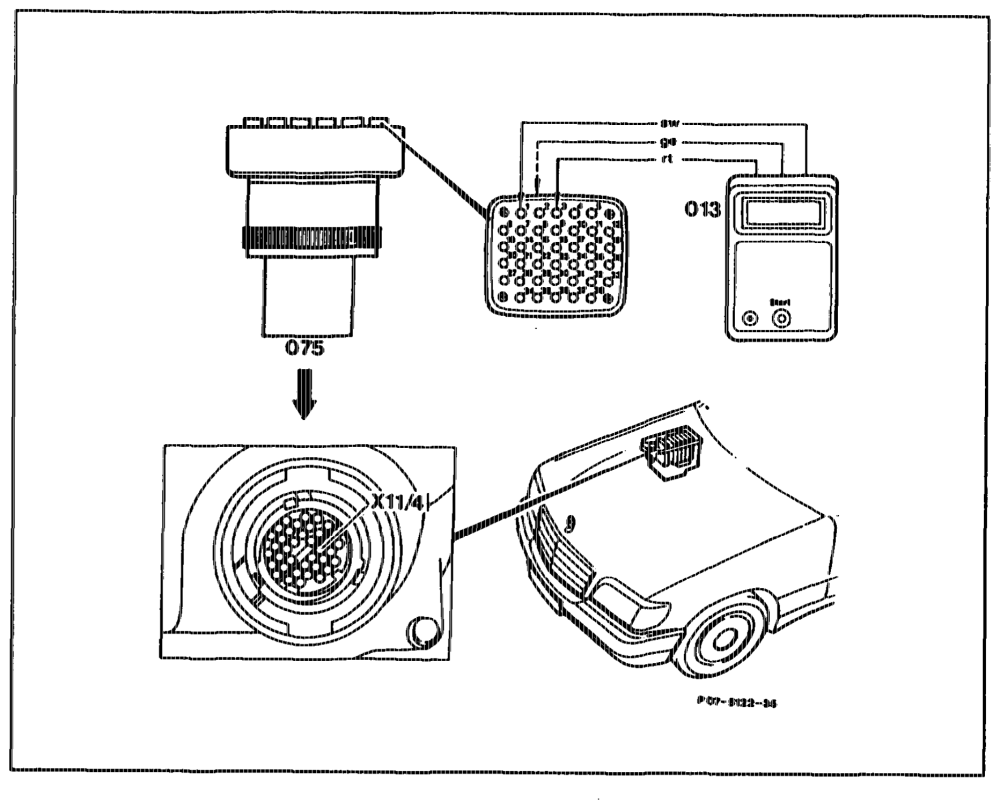
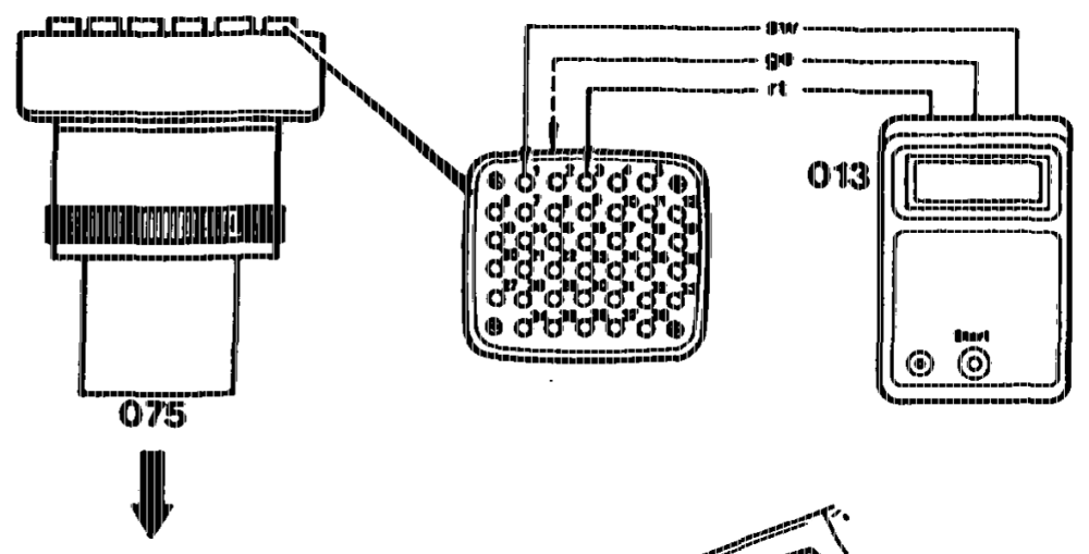
Connection diagram
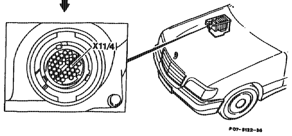
013 Pulse counter 075 Pulse counter adapter 11/4 = Test coupling for diagnosis, pulse signal (38-pin)
Contact assignment of pulse counter adapter
Ground, terminal 31 aoPTerminal 87 Terminal 30 EDS pulse readout
apn == RA 07,1.1042~1120/134
5 Once again press start button for between 2 Notes regarding pulse readout tf a complaint is received but no fault is and 4 seconds. The previous figure re-appears displayed via the pulse readout, perform the if no further fault is stored in the system. If a function test, section „e”. further fault is present in the system, its fault The figure 1 indicates no fault detected in the code is displayed. electronic system. All further figures are assigned to a particular component/fault group. 6 Repeat this procedure until the first fault is The figures from 1 to 15 appear in the display again displayed. field of the pulse counter. 7 Rectify noted faults (pulse readout) If the U-Batt LED lights up after connecting the according to troubleshooting schedule. pulse counter, pulse counter and pulse counter power supply are in order. 8 Perform components test.
1 Connect pulse counter as stated in the Erasing fault memory After a fault has been erased, the pulse connection diagram. displayed must be erased as follows:
Note The U-Batt LED in the display field must light 9 Press start button and read the rectified up; if not: fault, then press start button for 6–8 seconds. a) Check fuse of pulse counter. b) Test contact 1 of test coupling (X11/4) to
Note battery positive (11–14 V). Each fault displayed must be erased c) Test contact 4 of test coupling (11/4) to individually. Once the fault has been rectified and erased, contact 1 (6–12 V). the fault code no longer appears in the fault
2 Engine idling. output. If a figure greater than 1 is displayed, further lf the fault counter is read with the pulse counter with ignition „ON”, the pulse fault in the system. readout ”7” (engine speed sensor) appears.
3 Press start button for between 2 and 4 seconds.
4 Read off pulse output and note. Readout ”1” no fault stored. Greater than „1” = fault in system.
epthian = RA 07.1.1042-1120/135 c) Fault table
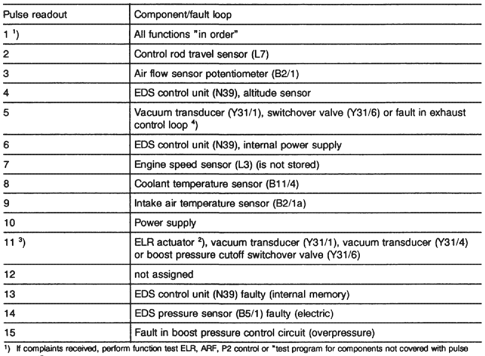
The figure in the display field of the pulse readout indicates whether and which component is faulty or whether components in the control loop are faulty.
output”. 2) Fault is not stored, readout if short-circuit and open circuit. 3) Readout only if open circuit. 4) Readout if interruption in pneumatic supply, e. g. vacuum line faulty.
aptine = RA 07.1.1042-1120/136 d) Test program with contact box
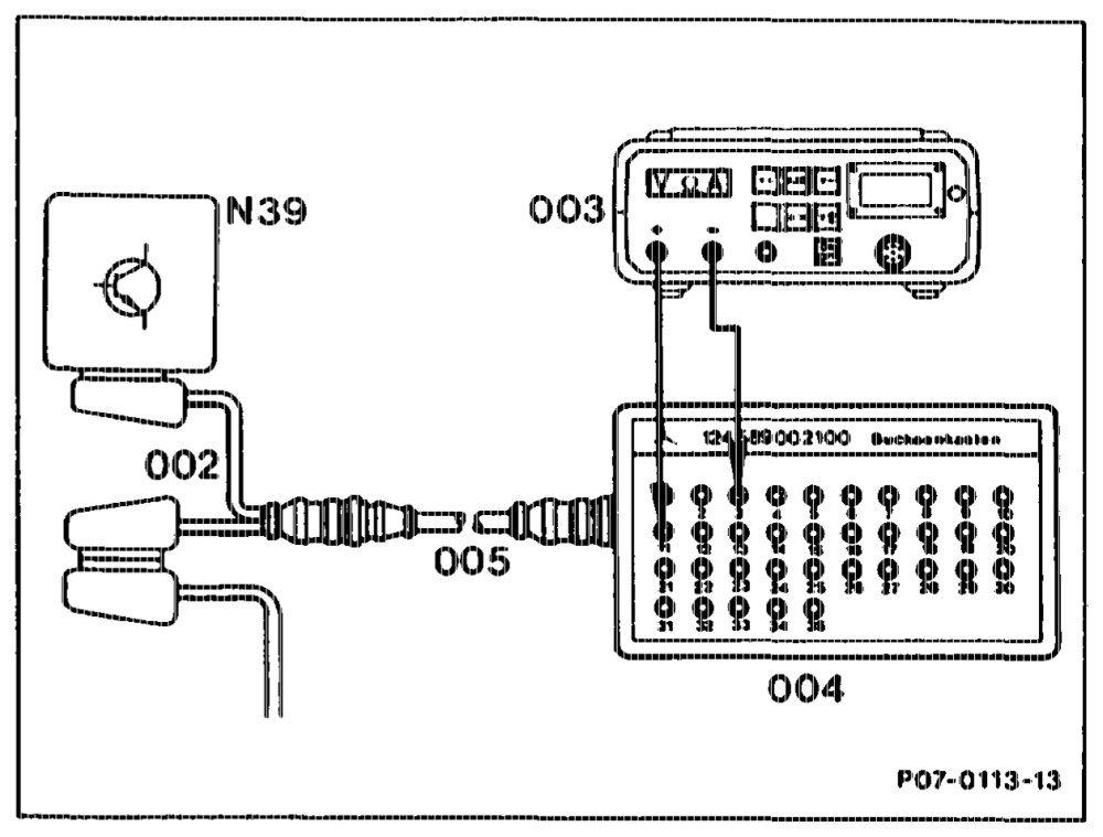
Connection diagram of contact box
002 25-pin test cable 124 589 33 63 00 003 Multimeter 004 35-pin contact box 124 $89 00 21 00 005 Test cable 124 589 34 63 00 N39 = EDS control unit
Symbols for test Instruments Contact box ~0=(Y)*oVoltage measurement (volts, DC Multimeter voltage) —{ Contact Resistance measurement (ohms) am Pin
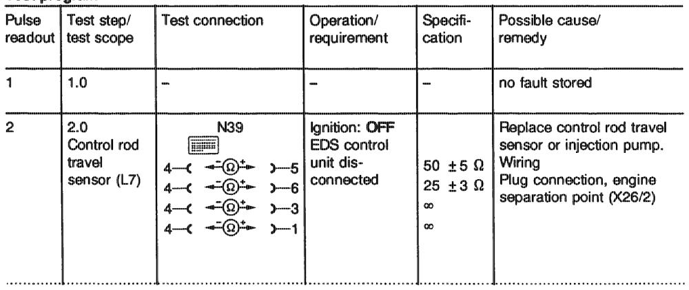
Test program
eptiiae = RA 07.1.1054~—1120/137
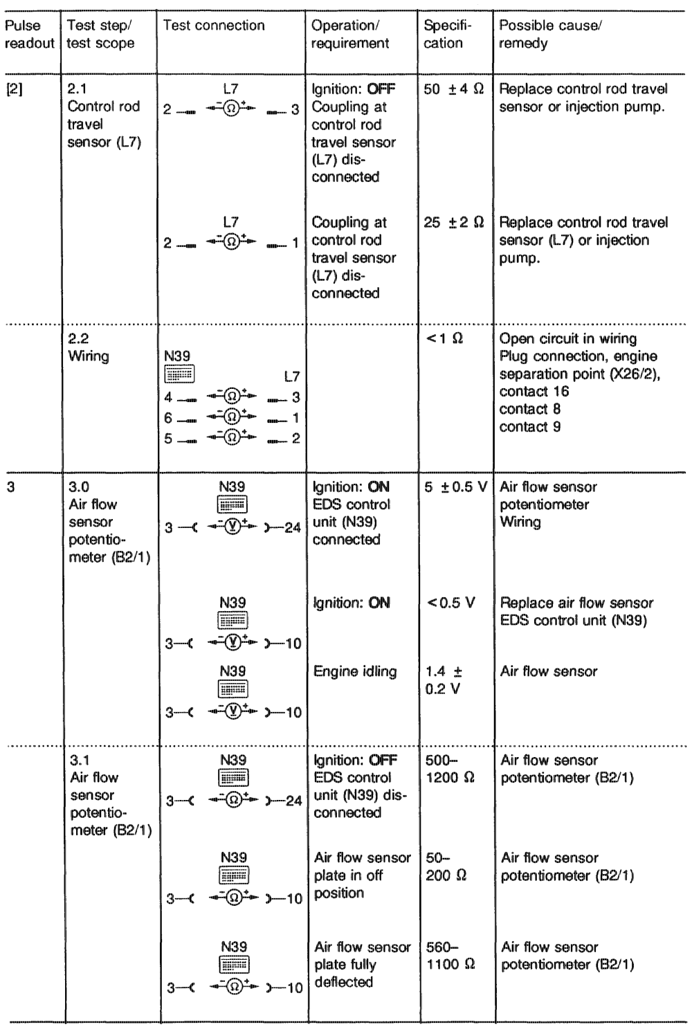
gti RA 07.1.1042–11 20/138
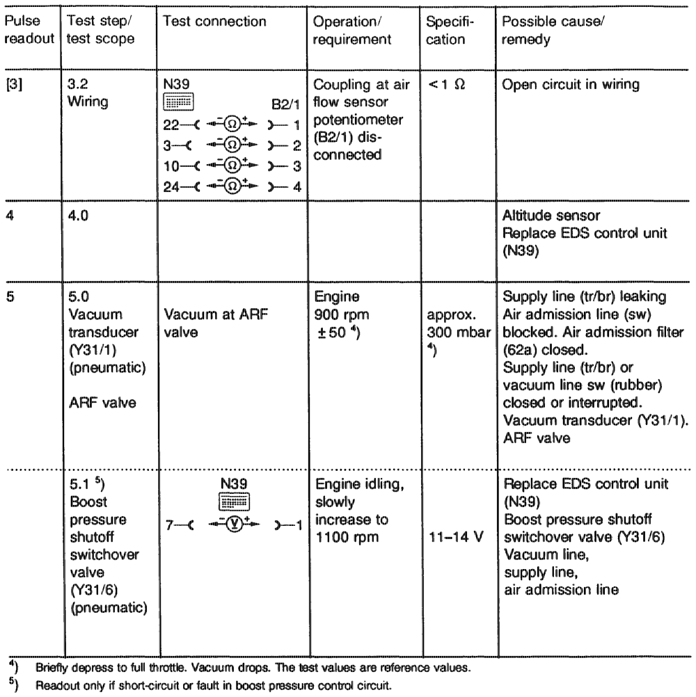
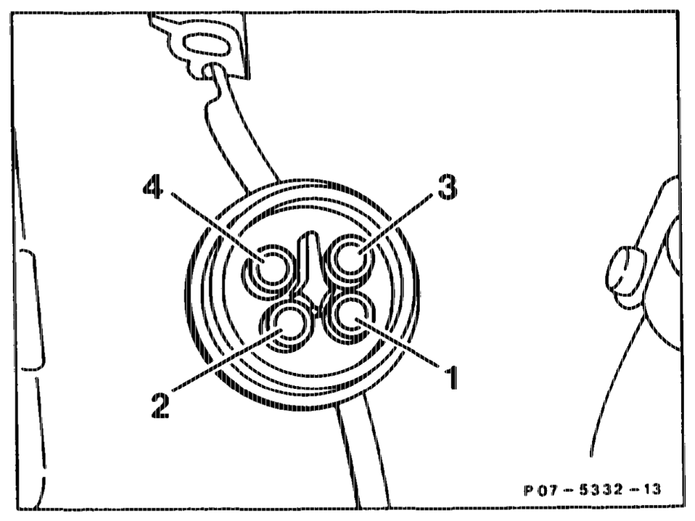
Contact assignment of plug connection, air flow sensor potentiometer (B2/1)
ptiin = RA 07.1.1054-1120/139
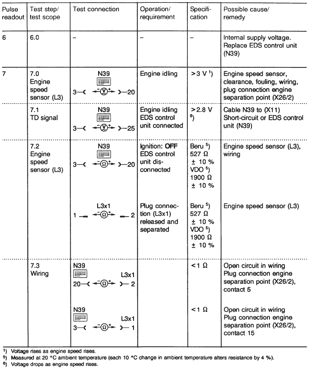
agthhijy = RA 07.1.1054~1120/140
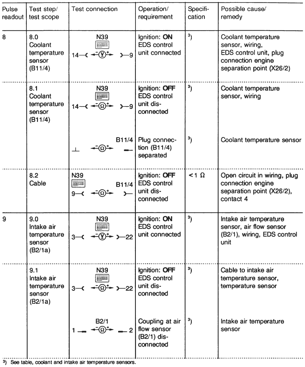
apttiis = RA O7.1.1042-1120/141
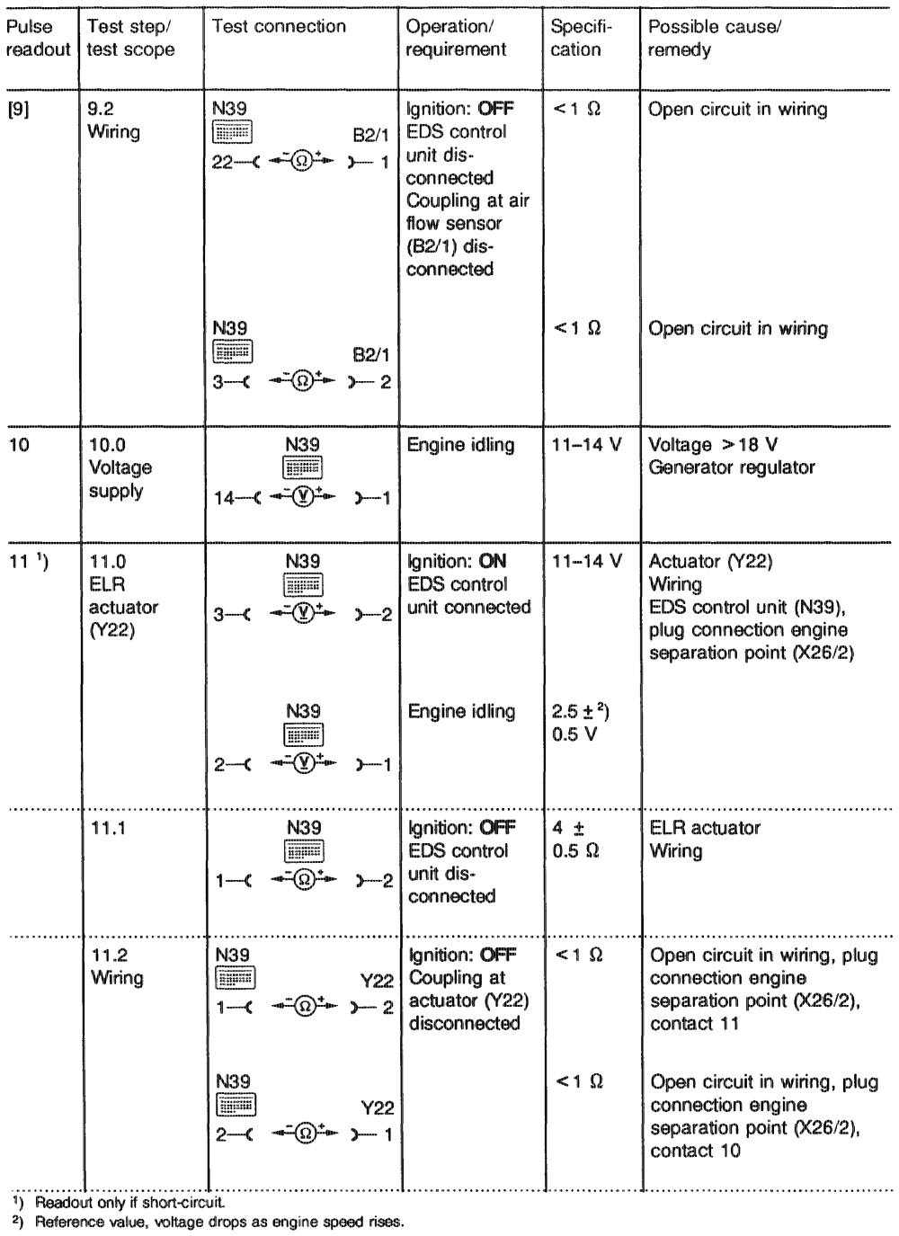
apis = RA 07.1.1054-1120/142
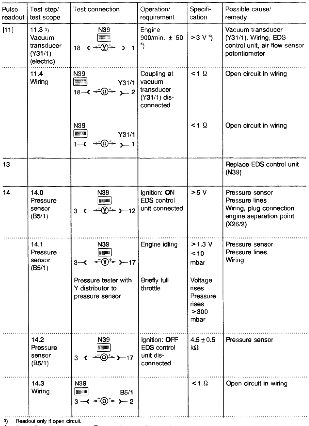
4) Apply full throttle. Voltage drops. The test values are reference values.
apihijn = RA 07.1.1054–1120/143
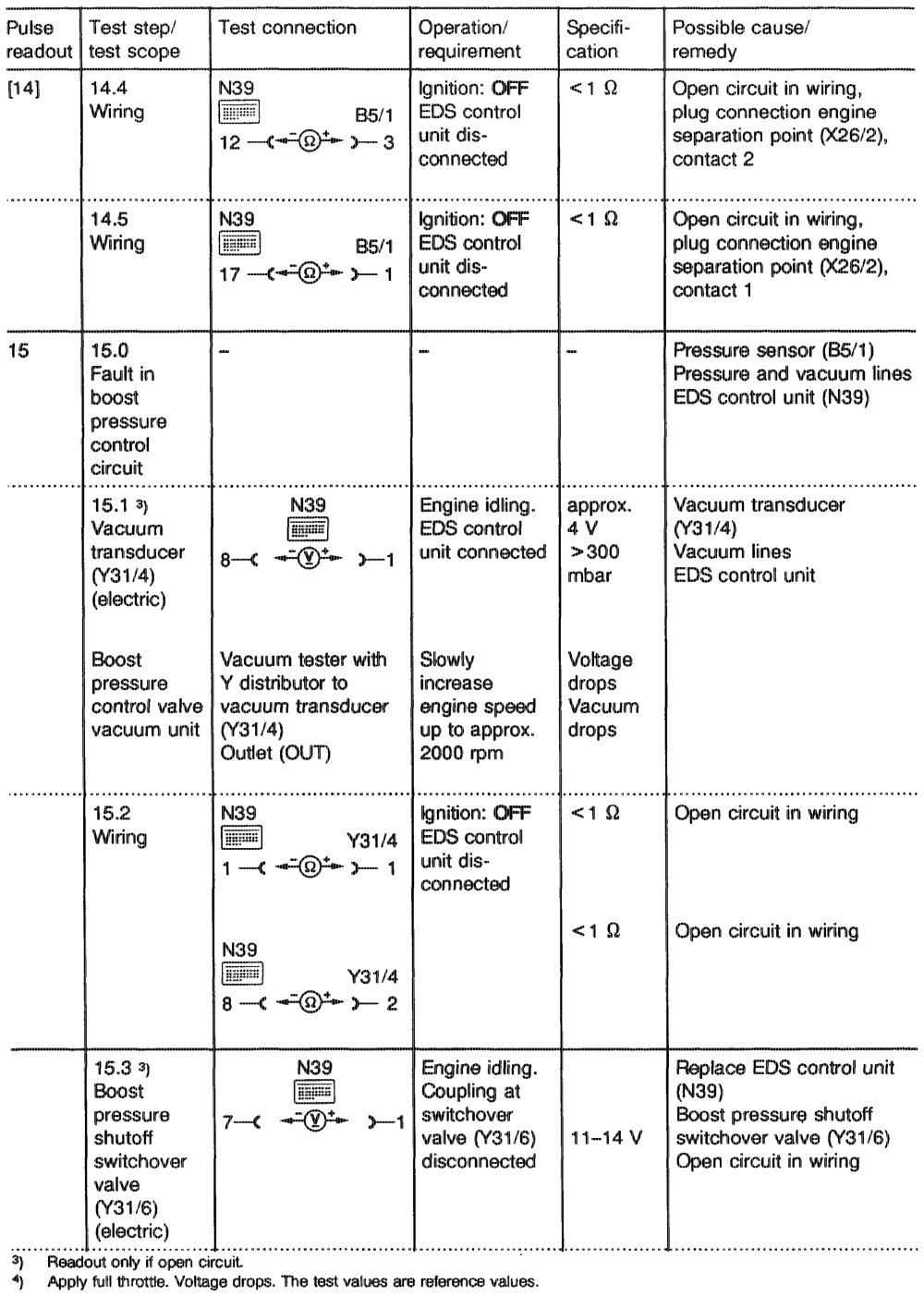
apihijn = RA 07.1.1042-1120/144
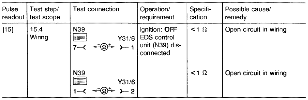
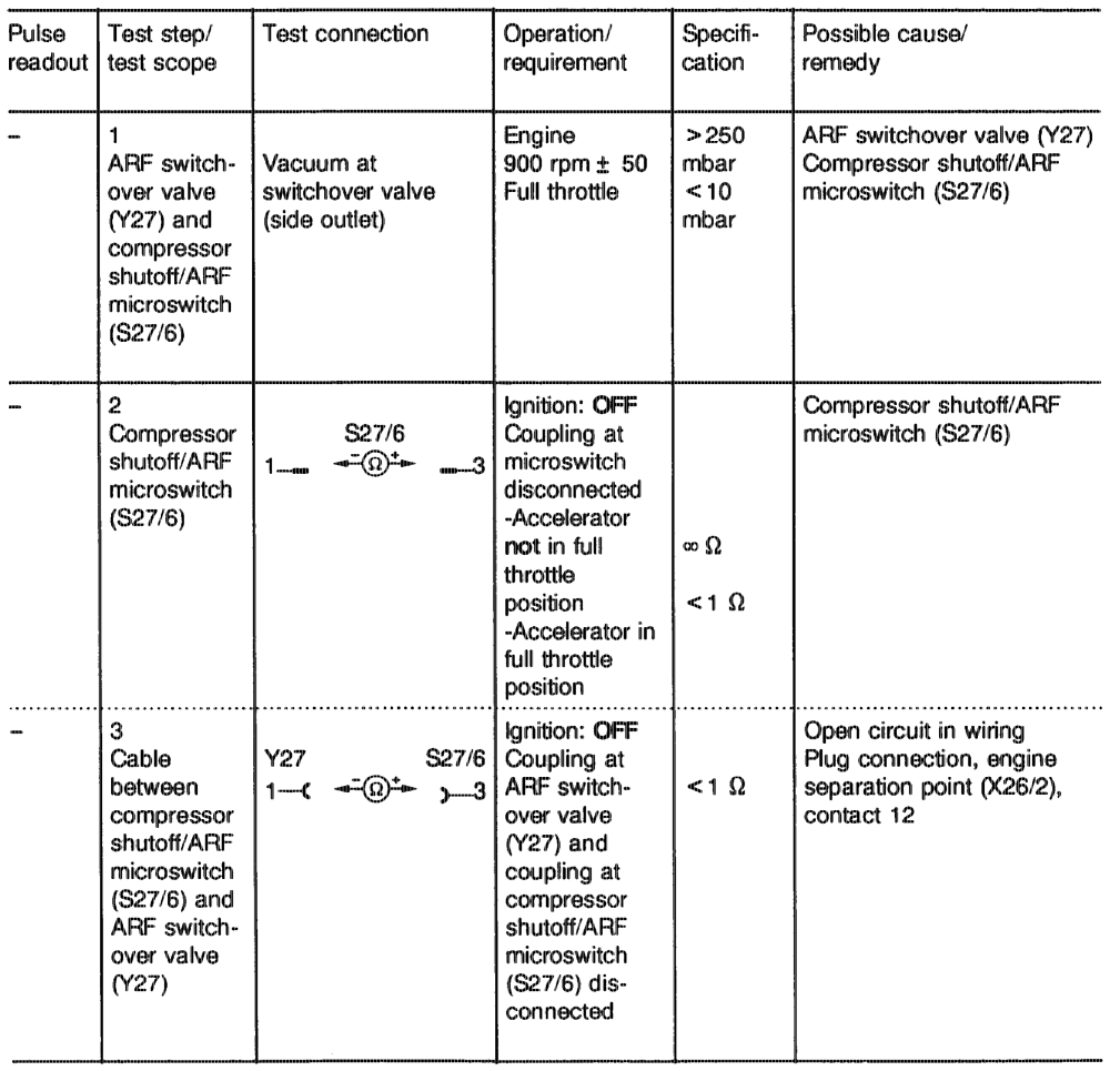
e) Test program for components not covered with pulse output
pine RA 07.1.1042-1120/145
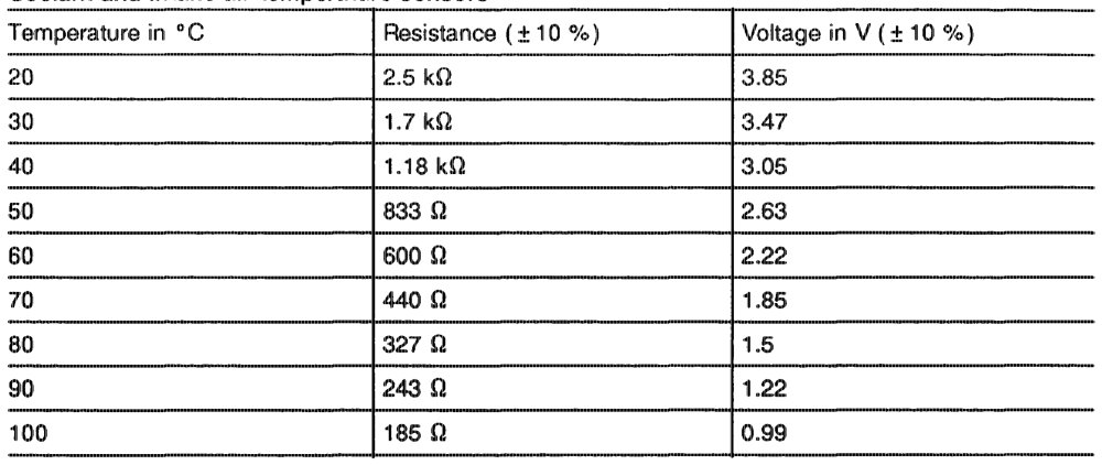
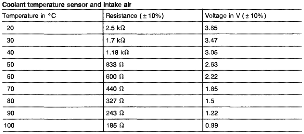
Coolant and intake air temperature sensors
gti = RA 07.1.1042~1120/146 f) Function test ELR, ARF, P2 control
Note
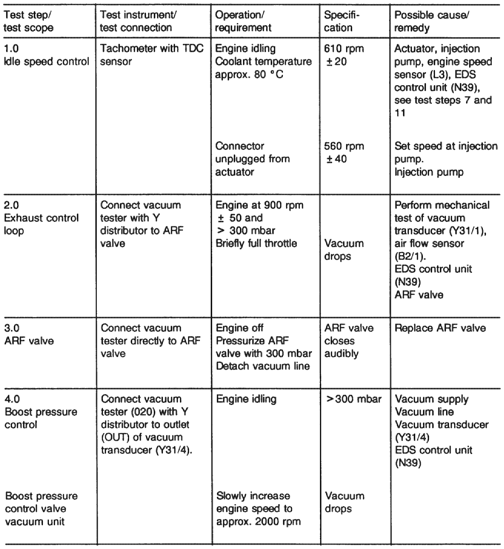
This test should only be performed if a complaint is received but no fault is indicated with the pulse readout.
eutthiyn = RA O7.1.1042-1120/147
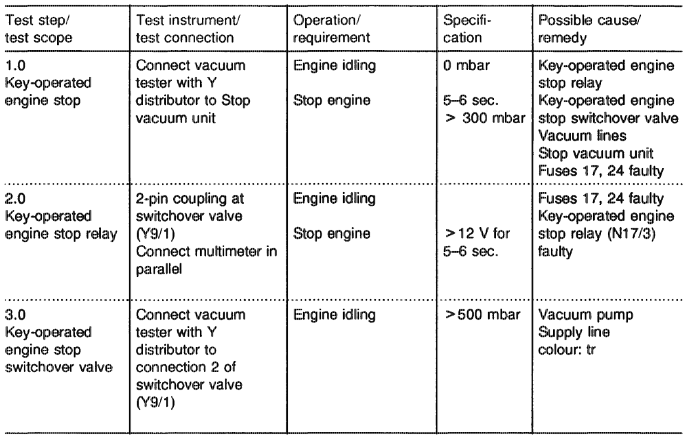
g) Testing key-operated engine stop
eptiiijm = RA 07.1.1042~-1120/148