Replacing valve guides
WIS 05-2850
Preceding work: Valve guides checked (05-2845).
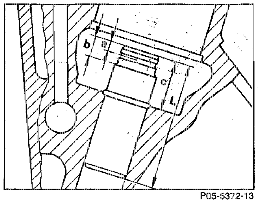
A. Engine 119.960/97 with nonferrous metal valve guides ad
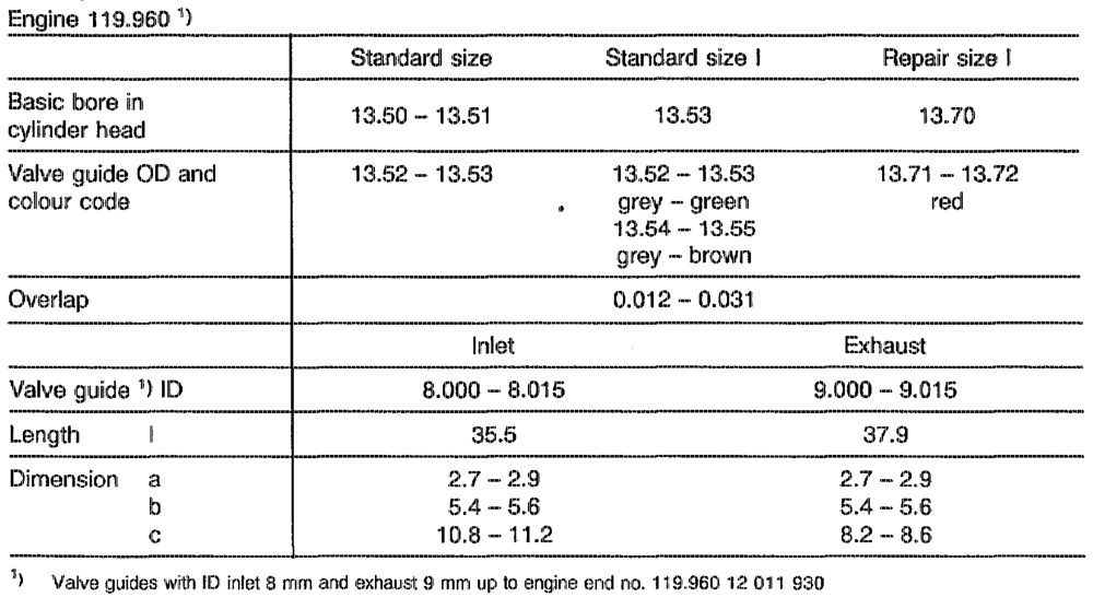
Valve guides and basic bores
awihie RA 05.1323-2850/1
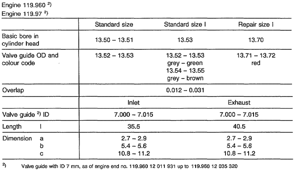
Valve guides and basic bores
119.970 12 021 286 119.971 12 010 034 119.974 12 004 781 119.975 12 004 281
ath RA 05.1323-2850/2
P05-5373–55
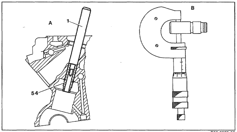
A Knock out valve guide B Measure valve guide OD
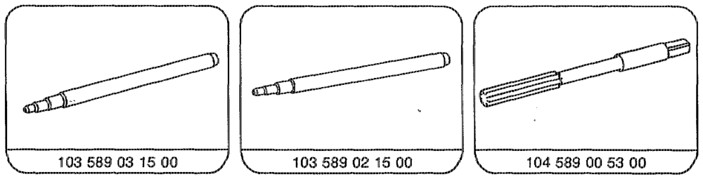
Valve guide (54) 2… ke ee eee wees knock out with drift (1) from combustion chamber side. Removal drift 103 589 03 15 inlet dia. 8 mm Removal drift 103 589 02 15 inlet, exhaust dia. 7 mm and 3 mm with basic bore 13.5 mm Measuring valve guide OD …… See eee eee eee measure with rnicrometer. Determine which valve guide is installed. Match up next larger valve quide, see table. Basic bore in cylinder head …………006. ream to standard size or to repair size depending on matched valve guide.
othe §=RA 05.1329-2850/3
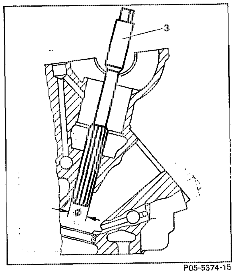
Standard size (Ream basic bore with reamer)
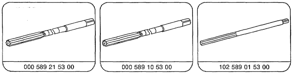
weet eee ewww eae rr ream through with reamer (3). Use reamer 104 589 00 53 00 for basic bore of 43.53 morn.
Note Lubricate with petroleum. Ream with only a slight pressure and do not twist rearner (3). Clean blades of reamer before each rearning operation.
tiie =RA 05.1323-2850/4.
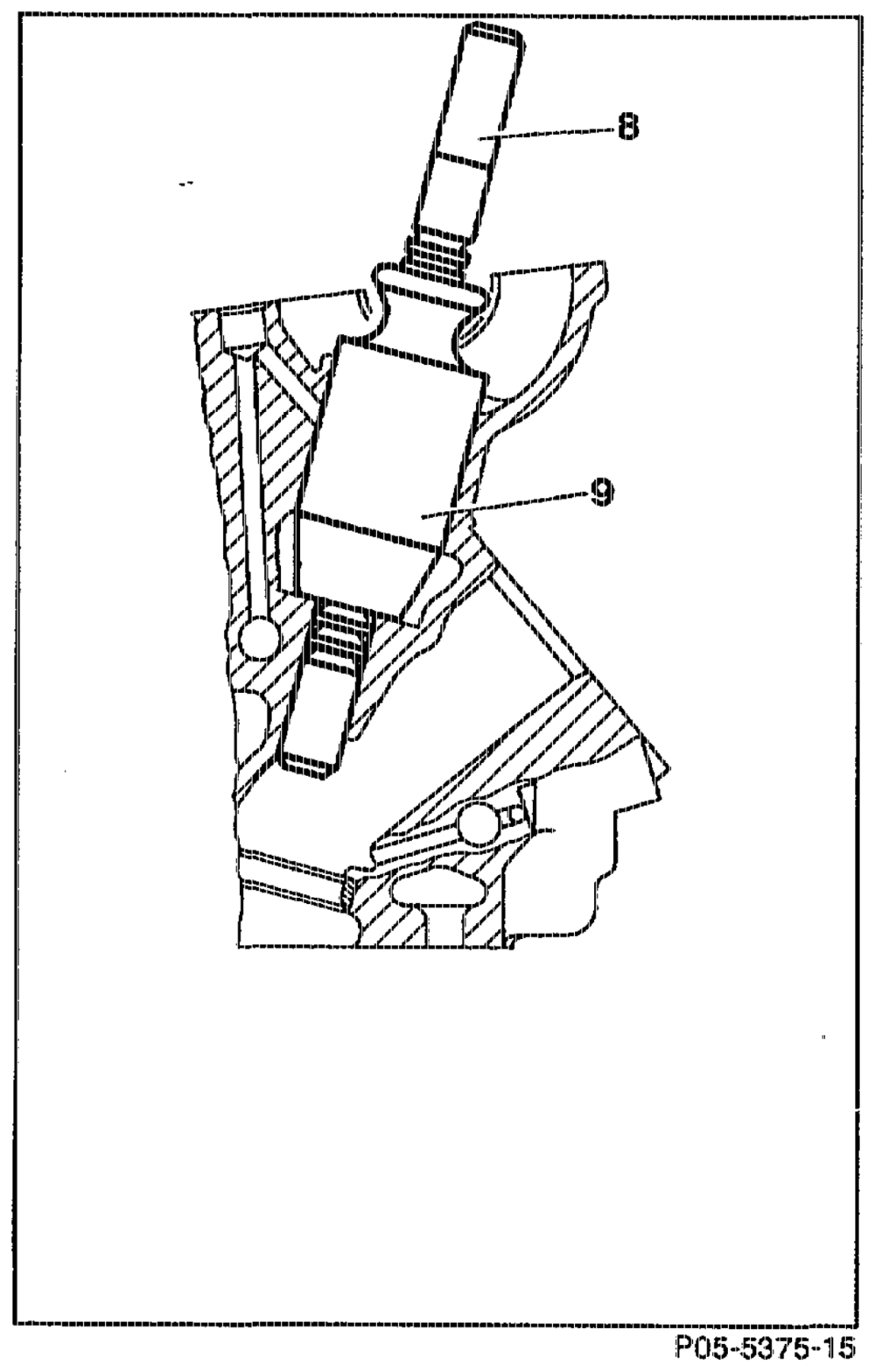
Repair size (Ream basic bore with broaching tool)
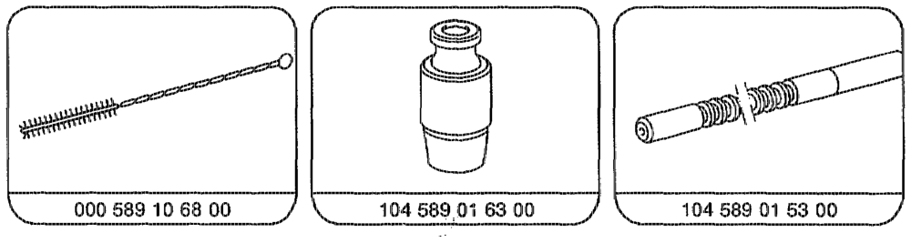
Blades of broaching tool (8) …. tee eee clean with cormpressed air or plastic brush before each broaching operation. Guide sleeve (9) and broaching tool (8) insert into bucket tappet basic bore. Use guide sleeve 104 589 01 63 00 and broaching tool 104 589 01 53 00 for basic bore 13.7 mm. Broaching tool (8) ……. ween eee press through.
Note Lubricate with petroleum. Clean broaching tool (8) with compressed air after each broaching operation.
ati =A 05,1923-2850/5
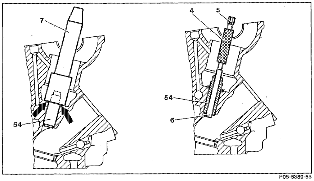
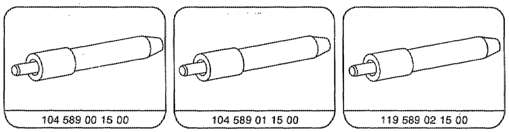
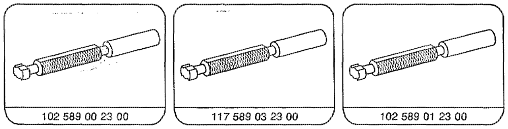
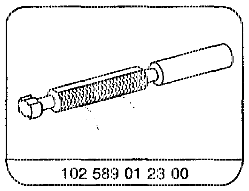
Valve guide (54) eee ee eee eee sae supercool in liquid nitrogen (about 3 minutes). If no liquid nitrogen is available ………… . heat cylinder head in water bath to approx. 80 °C. Valve guide (54) 2… ee eee ee ee kriock in as far as stop (arrows) with insertion drift (7). Insertion drift 104 589 00 15 00 inlet @ 8mm. Insertion drift 104 589 01 15 00 exhaust @ 9mm. Insertion drift 119 589 02 15 00 inlet, exhaust O 7mm. Valve guide (54) …….0….00.052202+.-. Check if tightly seated if cylinder cool. ID of valve guide (54) ……………….. Check with gauging drift (4). Gauging drift 102 589 00 23 00 inlet dia. 8 mm. Gauging drift 117 589 03 23 00 exhaust dia. 9 mm. Gauging drift 102 589 01 23 00 inlet, exhaust dia. 7mrn. Go side (6) of gauging drift (4) ………….. must be possible to insert fully. Orr See eee eee eee eee ream with reamer, if necessary. Reamer 000 589 21 53 00 inlet dia. 8 mm. Reamer 000 589 10 53 00 exhaust dia. 9 mm. Reamer 102 589 01 53 00 inlet, exhaust dia. 7 mm.
within RA 05.1923-2850/6
otiin RA 05.1323-2850/7
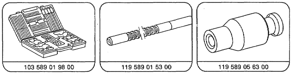
Special tools
Cylinder head tensioning device e.g. Hunger D-8000 Minchen 70 Order no. 221.60.000
Micrometer 0.25 mm
wiki RA 05,1323-2850/8
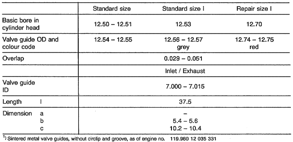
Valve guides 1) and basic bores
119.970 12 021 287 119.9714 12 010 035 119.972 as of start of production 119.974 12 004 782 119.975 12 004 282 119.98 as of start of production
oti §=RA 05.1323-2850/9
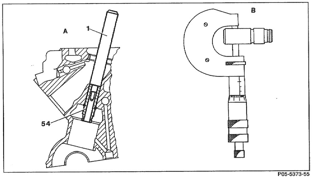
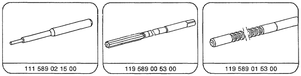
knock out with drift (1) from combustion chamber side. Removal drift 111 589 02 15 00 inlet, exhaust 7 mm with basic bore of 12.5 mm.
Measuring valve guide OD measure with micrometer. ee Determine which valve guide is installed. Match up next larger valve guide, see table. Basic bore in cylinder head rear to standard size according to matched valve guide.
broach repair size |.
whbin RA 05.1323-2850/10
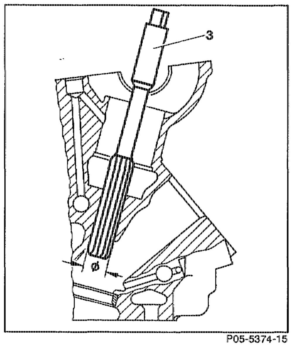
(Ream basic bore with reamer)
ream through with reamer (3). Use reamer 119 589 00 53 00 for basic bore of 12.53 mm.
Note Lubricate with petroleum. Ream with only a slight pressure and do not twist reamer (3). Clean blades of reamer before each reaming operation.
athe RA 05.1323-2850/11
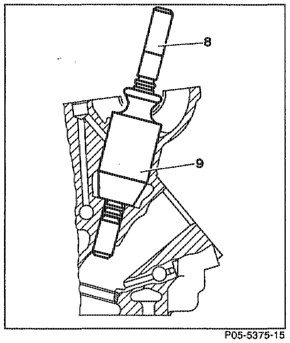
Repair size (Rear basic bore with broaching tool)
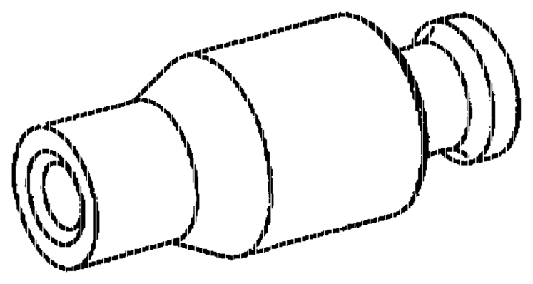
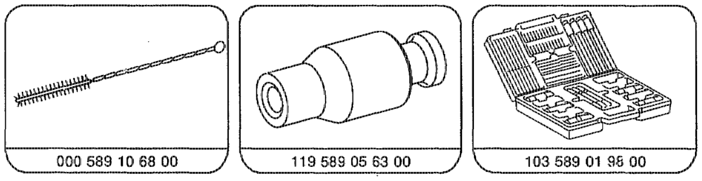
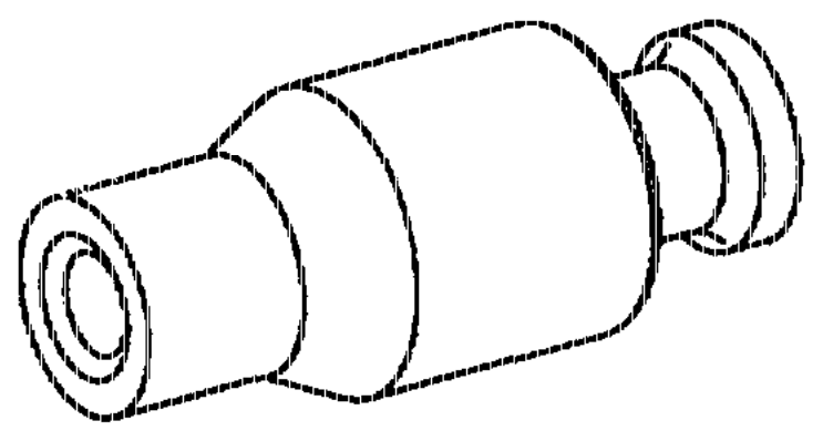
clean with compressed air or plastic brush before each broaching operation. insert into bucket tappet basic bore. Use guide sleeve 119 589 05 63 00 and broaching tool 119 589 01 53 00 for basic bore 12.7 mr. press through.
Note Lubricate with petroleurn. Clean broaching tool (8) with compressed air after each broaching operation.
wtih RA 05.1323-2850/12
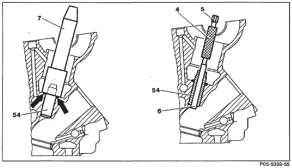
Inserting valve guide, checking ID
moisten on outside with oil.
Note It is not necessary to heat the cylinder head or to cool the valve guide (54).
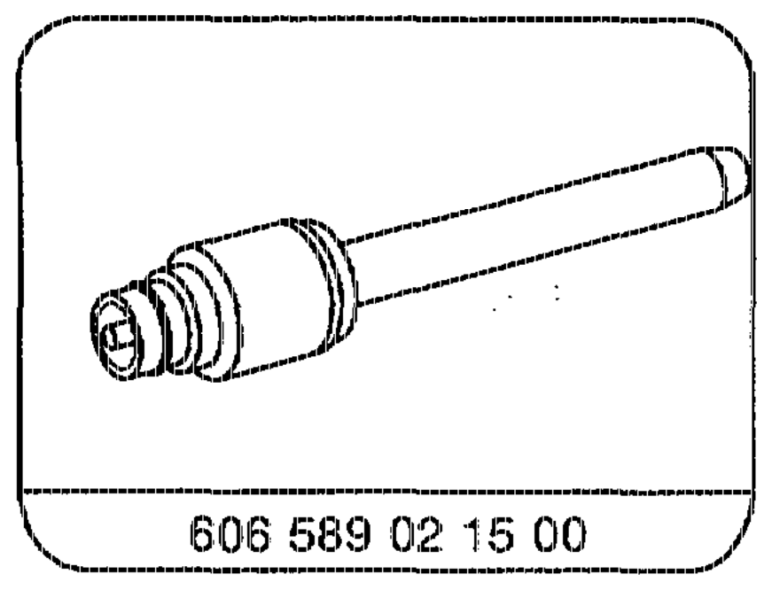
knock in as far 2 Valve guide (54) S$ stop (arrows) with insertion drift (7). Insertion drift 606 589 02 15 00 inlet, exhaust @ 7 mm,
Note The circlip is not fitted to the sintered metal valve guides. The insertion depth is fixed by the insertion drift.
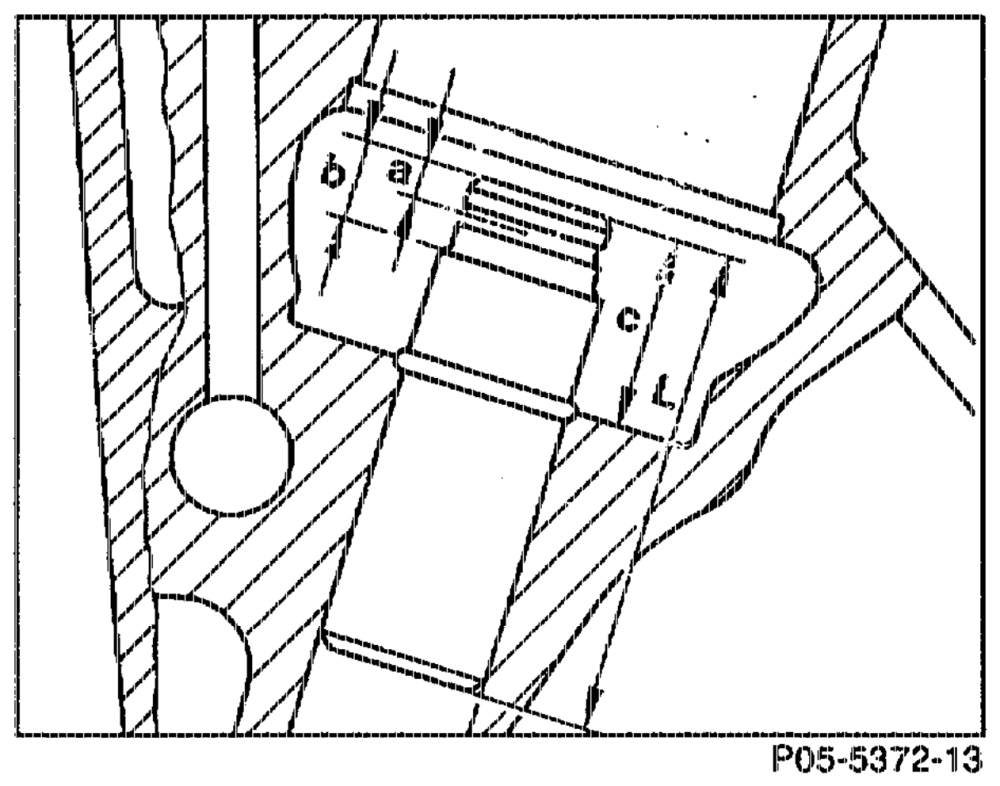
Installation depth (c) of valve guide (54) check, correct if necessary. Valve guide (54) clean.
Cylinder brush 000 589 10 68 00 Valve guide (54) check to ensure tight.
ID of valve guide (54) check with inspection drift (4). Inspection drift 102 589 01 23 00 inlet, exhaust © 7mm.
inn RA 05.13923-2850/13
Go side (6) of gauging drift (4) ……. pean +. must be possible to insert fully. aN if it is not possible to insert the gauge, the valve guide should be replaced as the material of the sintered metal versions is too hard for rearning.
Commercially available tools Cylinder head clamping device e.g. Hunger D-8000 Munchen 70 Order no. 221.60.000
otie RA 05.1323-2850/14