Removing and installing engine
WIS 01-0300
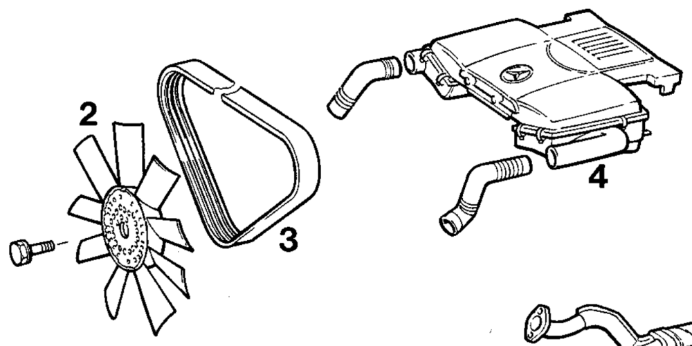
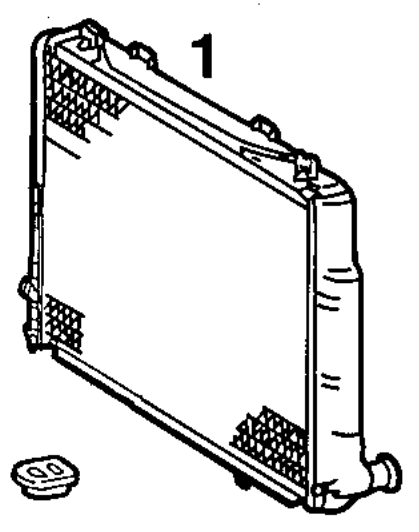
Preceding work: Operation no. of operation texts and work units or standard texts Air cleaner (4) removed (09-0015). and flat rates Bottom engine compartment panel removed 01-2400, 2800 (Maintenance Manual 6190). Radiator removed (20-4200).
A. Models 124, 129, 140
P01-5049–59
Engine 119, model 140
Ground cable at battery disconnect, connect. Coolant at crankcase… 1.1 eee ee eee ee drain.
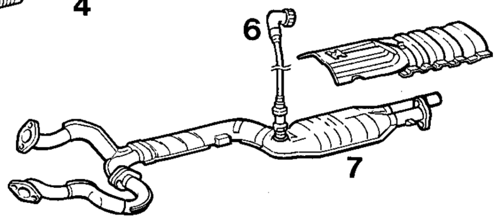
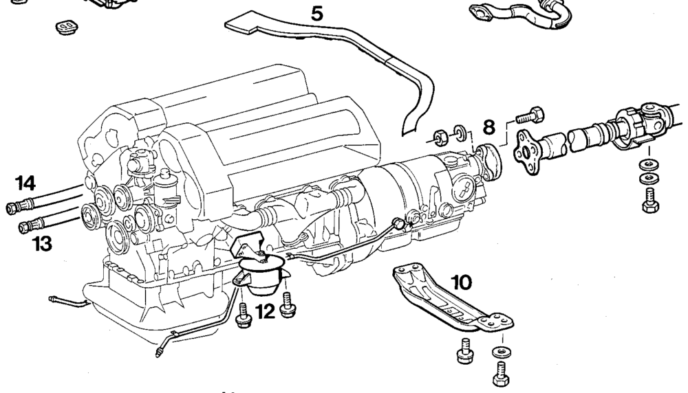
aim = RA 01.1313-0300/1 lf AC fitted: guard plate at condenser ……………. attach, remove. Model 140: left Bowden cable (engine compartment lock) detach, attach. Heating water lines at rear of intake manifold and at connection pipe to rear. of crankcase 2. eee eee eee ee detach, attach. Viscous fan clutch with fan (2) ……….– remove, install (20-3120). If AC fitted: poly V-belt (3)… ee eee eee eee remove, install (13-3420). Fuel lineS 2.0… ee eee take off, seal with special tool 000 589 40 37 00, fit on. Open fuel filler cap briefly beforehand. Electrical connections (engine wiring harness) . detach, attach. Vacuum lines 0… cee eee eee detach, attach. Bowden cable (accelerator control) ……… remove, install (30-0025). Model 124: accelerator control linkage at rear remove, install. Vacuum line of brake servo unit ……….. unbolt, bolt on. Power steering pump, oil in reservoir ……. extract, special tool 112 589 00 72 00. Adjust oil to correct level (46-0715). Oil tines of power steering pump ………. detach, seal, attach. If air injection fitted: air pump plug connection detach, plug in. Model 124: front bumper remove, install (88-2000). Model 124: right headlamp ………….. remove, install (82-4730). Model 124: air duct, left engine mount cooling . remove, install. Model 140: oil cooler line bracket ………. unbolt, bolt on. Oil cooler lines at air-to-oil cooler (13) and (14) unboit, seal, bolt on (18-1300). Model 124: left oil cooler line (13) at oil sump unbolt, bolt on. If level control fitted: high pressure hose ….. unbolt, bolt on. Model 124: left oil line, automatic transmission unbolt, bolt on. Bolt for piping behind AC compressor ……. unbolt, bolt on (25 Nm). AC compressor (11) with piping connected detach, place to the side, attach (83-5300). Plug connection, oxygen sensor (6) (lambda sensor) …….0.. eee eee eee eee disconnect, connect. Exhaust system (7) complete …………. remove, install (49-0045, 49-0170). Shield over starter «6.1… cece eee ee eee unbolt, bolt on. Model 129: electrical connection, starter ….. detach, attach. Wiring harness, starter and alternator from engine and transmission unbolt, bolt on. Model 124: strut below oil sump ……….- unbolt, bolt on.
wie RA 01.1313-0300/2
Propeller shaft of flexible coupling (8) ……. detach, attach. Replace self-locking nuts (41-0050).
Note Flexible coupling remains on transmission. Clamping nut and intermediate bearing attachment of propeller shaft …………. slacken, tighten (41-0050). Ground cable at transmission …………. unbolt, bolt on. Rear engine carrier (10) without engine mount remove, install (22-2120). Bracket of exhaust at transmission ……… unbolt, bolt on. Shift rod at transmission ……………. detach, attach. Electrical connections at transmission ……. disconnect, connect. Front engine mounts (12) on left and right from below 2.2… eee eee ee eee unbolt, bolt on (22-2110). Model 124: sealing strip of component compartment panel ………..0 02 ewes pull off, fit on. Engine hoist at lifting eyes …………… attach, detach. Engine with engine hoist ……….+++06. move into angled position and raise. Model 129: wiring harness of alternator …… unbolt, bolt on. Engine 2… eee cece eee remove, install. Front and rear engine mounts ………… examine. Coolant, oil and fuel hoses… 2.2… eee examine. Automatic transmission, Bowden cable for control pressure ………….00 eee eee adjust (27-110). Idle speed 2… ee ee es check, adjust. Oil drain plugs… 2.0… eee eee eee check tightening torques. Oil level in engine and transmission …….. adjust to correct level. Coolant 22… eck ee eee eee eee pour in, check anti-corrosion/anti-freeze concentration and adjust to correct level (20-0100). Cooling systeM «ww. ee ee eee check for leaks, special tool 124 589 15 21 00 (20-0170).
Engine 2… eee eee eee
run. Engine leaks cece ee ee eee check.
Note Faults stored as a result of disconnecting cables or simulation during removal and installation or test operations, should be processed and erased in the fault memories after completing the work. Re-code or normalize radio and power windows, as appropriate. Perform final control actuations. Diagnosis Manual Volume 2, Index 0: Connecting and using test equipment.
wile RA 01.1313-0300/3
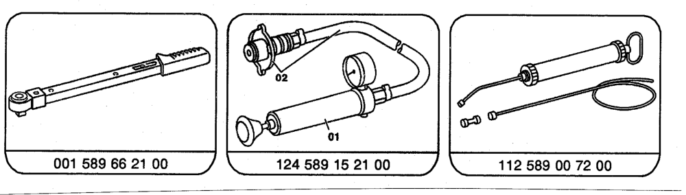
Commercially available tools Engine hoist No. 3188 e.g. Backer GmbH self-locking und CO KG D-42895 Remscheid
Shop-made tool
Guard plate for radiator/condenser Dimensions approx. 400 x 680 x 1
a@im RA 01.1313-0300/4
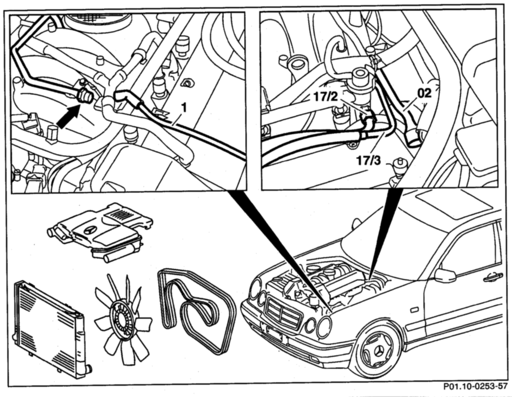
Preceding work: . Operation no. of operation texts and work units or standard texts Bottom engine compartment panel removed and flat rates (Maintenance Manual 6190) 01-2400 Viscous fan removed (20-3120) Radiator removed (20-4200)
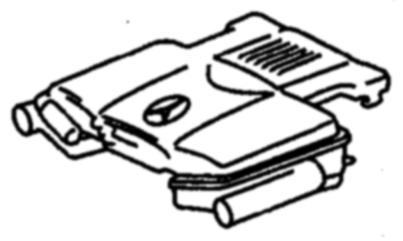
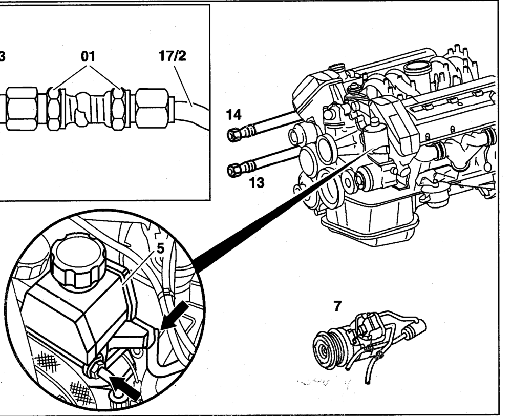
Cover over intake manifold …………+..4– remove, install. If A/C fitted: guard plate …………22 eee attach at condenser, take off. If A/C fitted: poly V-belt ………….0 02 eee remove, install (13-1200). Engine wiring harness ……….–2-200005 disconnect, connect (01-0310). Vacuum pipe (arrow) to brake servo unit at intake manifold ………00ee cece eee eens unboit, bolt on. Purge pipe (1) 2… eee eee eee disconnect, fit on. Fuel filer cap… ee eee eee open to release pressure in fuel tank. Fuel pipes (17/2) and (17/3) at fuel distributor PIPE… ce eee eee disconnect, connect.
Note Use box wrench bit (02) 000 589 68 03 00 to disconnect fuel pipe (17/3) and connect.
wim RA 01.1313-0300/5
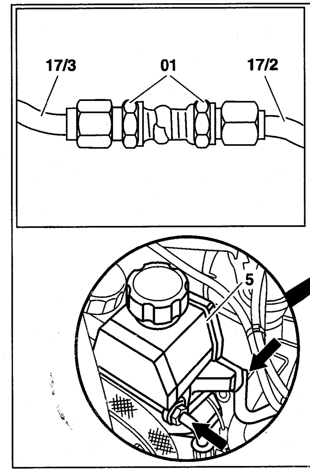
P01.10-0254–57
Fuel pipes (17/2 and 17/3) seal with fitting (01) (shop-made). Power steering pump: extract oil from reservoir with priming pump 112 589 00 72 00 for sampling oil.
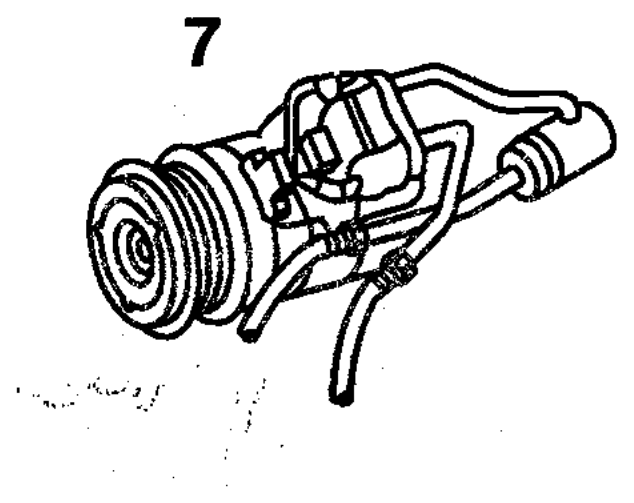
Note Fill, bleed power steering pump (AR46.30-0010A). Suction and delivery oil pipes (arrows) at power steering pump (5) disconnect, connect. Vacuum pipe at rear of intake manifold pull off, fit on. Electric wiring of O2 sensors at bracket at rear of transmission bell housing detach, attach. If air-oil cooling fitted: oil cooler pipes (13, 14) at oil cooler. unbolt, bolt on. If A/C fitted: A/C compressor (7) with connected unboit, bolt on, attach to side of engine piping compartment.
a@im RA 01.1313-0300/6
P01.10-0255–57
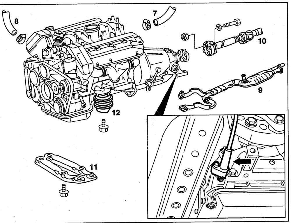
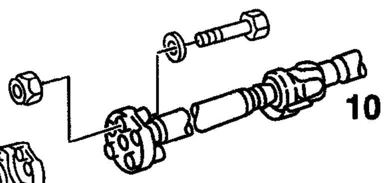
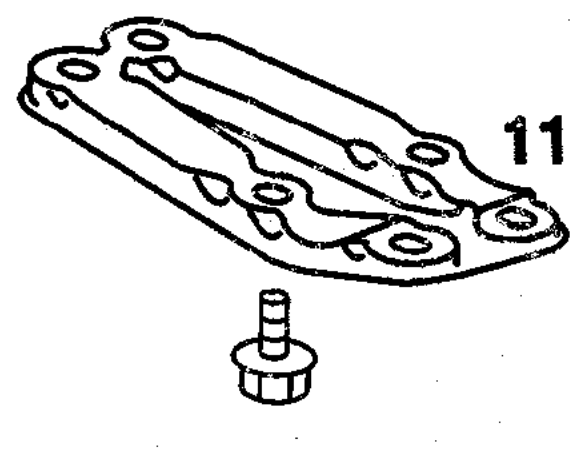
Coolant at crankcase «1… ee eee drain (20-0100). Coolant hoses (7) and (8) ………..0000ee disconnect, connect. Exhaust system (9) at exhaust manifold and transmission intermediate mount ………… unbolt, bolt on. Front propeller shaft (10) at transmission …… unbolt, bolt on (AR41.10-0050B). Propeller shaft (10) ee eee eens push to the rear. Rear engine support (11)… 2.2… eee ee eae remove, install (22-2120). Transmission cable (arrow) for park lock ……. unclip at transmission, clip into place (AR27.60-0500-05A).
A The cable must only be disconnected when selector lever in position „P”. Selector rod 2… 1… cee eee eee eee detach, attach. Front engine mount (12) at front suspension CAVICr oe eee ee eee ete ee eee unbolt, bolt on (22-2110).
ati RA 01.1313-0300/7
P01.10-0256–37
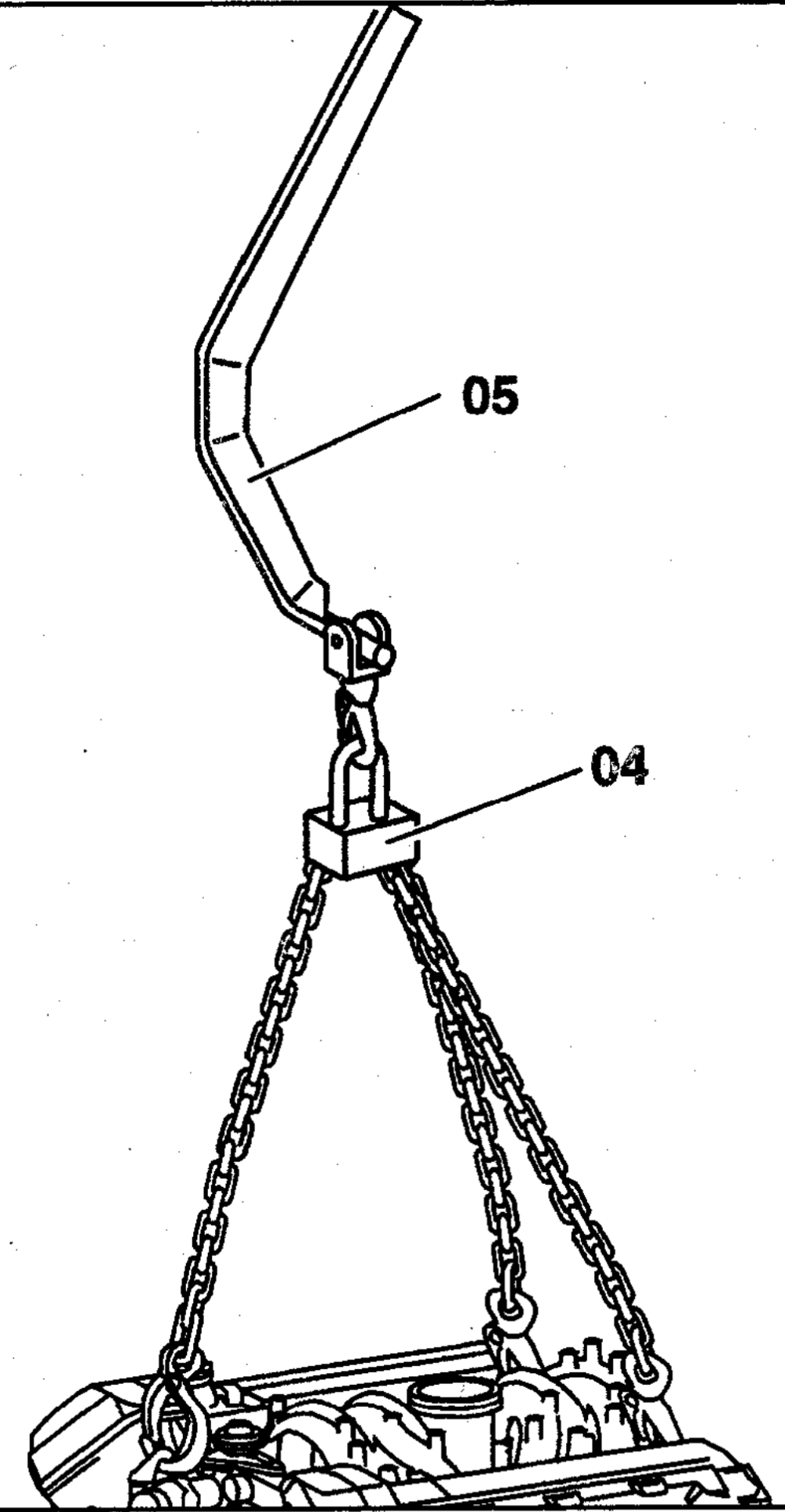
Engine hoist (04) «0… cee ee eee eee attach to the three lifting eyes of the engine with engine supporting bar (05), detach. Engine with transmission ………….00005 move into sloping position. Engine cee ee ee eee eee remove, install. Front and rear engine mounts ………….. inspect. Oil drain plugs «1.1… cece ee eee check tightening torques. Engine and transmission oil level …………- adjust to correct level. Coolant cece eee ee eee eee eee pour in, check anticorrosion/antifreeze agent and adjust to correct concentration (20-0100). Leaktightness 0. cee eee eee eee check.
wie RA 01.1313-0300/8
or simulation during removal and installation or test operations, should be processed and erased in the fault memories after completing the work. Re-code or normalize radio and power windows, as appropriate. Perform final contro! actuations. Diagnosis Manual Volume 2, Index 0: Connecting and using test equipment.
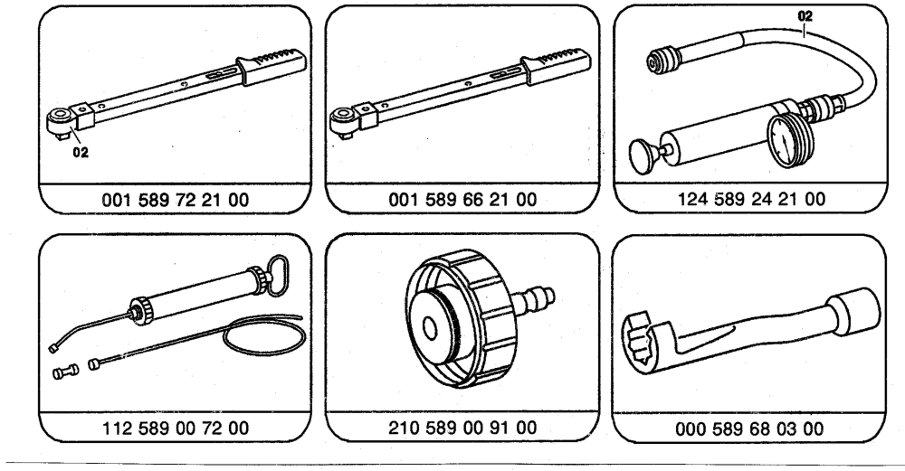
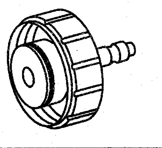
Special tools
wim RA 01.1313-0300/9
Commercially available tools Removal device equipment model 3188 e.g. Backer GmbH und CO KG (lifting capacity 500 kg) 42895 Remscheid
Engine supporting bar e.g. Schairer WeidenstraBe 5 72459 Albstadt Order no. 0304.01.001
Shop-made tool
Guard plate for radiator/condenser Dimensions approx. 400 x 680 x 1 mm
iim =RA 01.1313-0300/10