Testing electronic accelerator
WIS 30-365
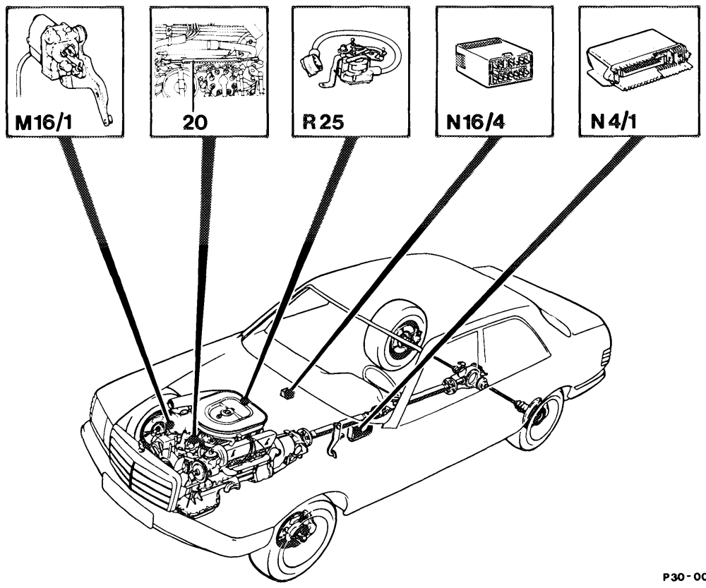
0098 – 57
M16/1 Electronic accelerator actuator R25 Accelerator pedal position sensor N4/1 Electronic accelerator control unit N16/4 Fuel pump relay with kickdown cut-out 20 Idle travel rod (redundancy rod)
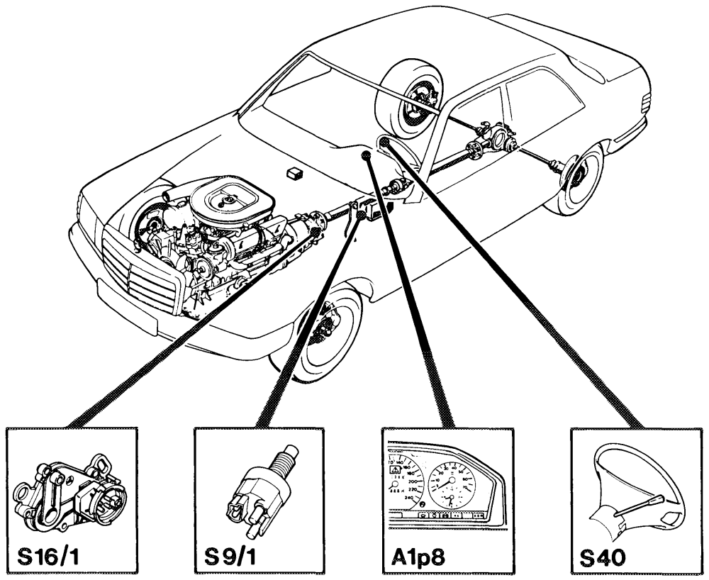
P300099–57
A1p8 Electronic speedometer S16/1 Starter lock-out/backup lamp switch Cruise control switch sot Stop lamp switch (4MATIC/ASD) S40 V Decelerate/set
B Accelerate/set
SP Resume A Off
Special tools
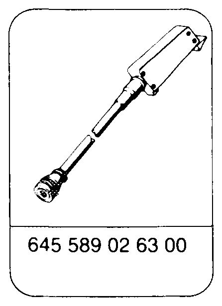
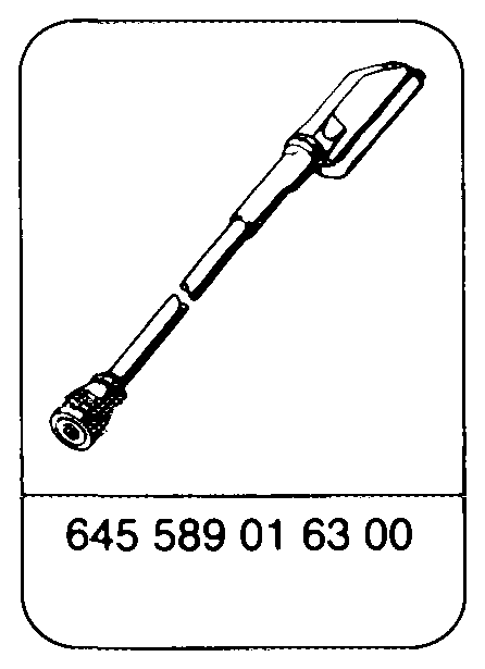
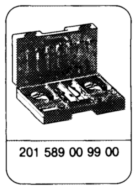
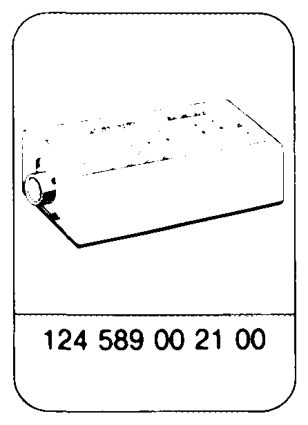
Commercial tool
Multimeter
e.g. Sun, DMM-5
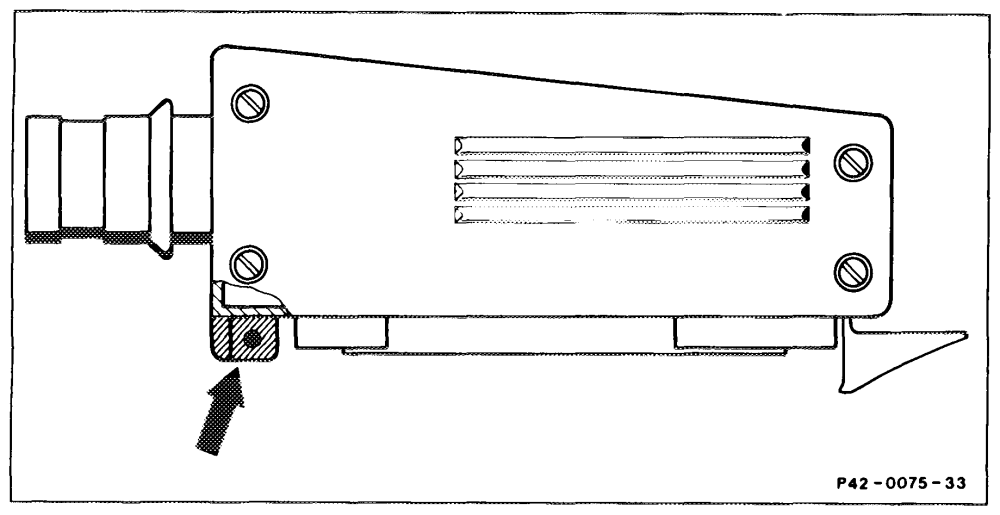
Multimeter =-©*= Multimeter, resistance mode Contact box =@*= Multimeter, D.C. voltage mode Battery Contact a Plug Jumper Ground
The stud (arrow) on the test cable 645 589 02 63 00 must be sawn off.
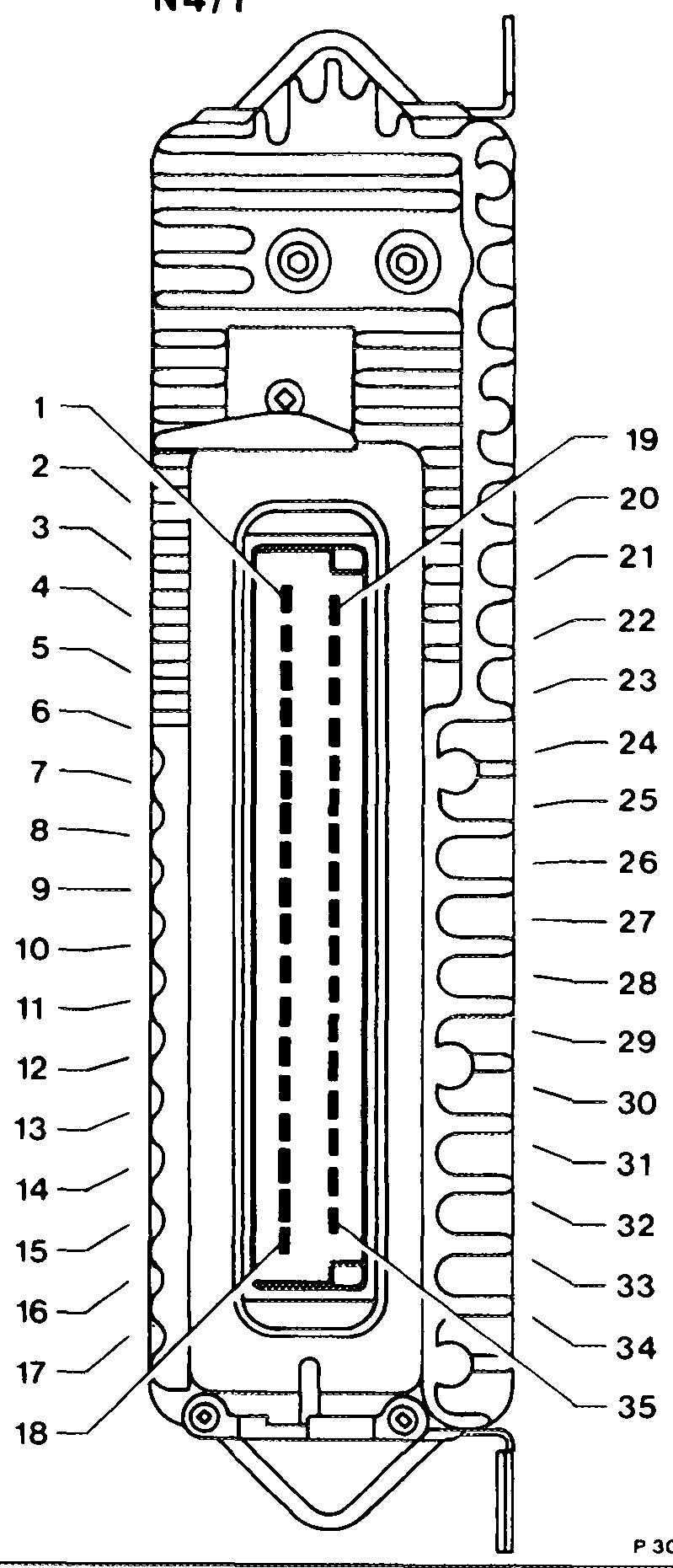
control unit
Voltage supply, terminal 15 unprotected MONOWhk WH = Voltage supply, terminal 15 unprotected Electronic accelerator actuator (motor) Electronic accelerator actuator (motor) Reference potentiometer (ground) Electronic accelerator actuator potentiometer (ground) Do not create contact! Engine 116, 117, 119: not assigned Engine 103, 104: idle speed switching signal to CIS-E control unit Reference potentiometer, voltage supply (+ ) Not assigned 10 Battery ground (W10) 1 Electronic speedometer speed signal 12 Safety switch, reference potentiometer 13 Stop light switch 14 Reference potentiometer (wiper signal) 15 Cruise control switch (Decelerate, Set) 16 Not assigned 17 Cruise control switch (Resume) 18 Do not create contact! 19 Electronic accelerator actuator (motor) 20 Electronic accelerator actuator (motor) 21 Battery ground (W10) 22 Battery ground (W10) 23 24 Not assigned Not assigned 25 Electronic accelerator actuator, potentiometer 26 (voltage supply) Not assigned 27 Electronic accelerator actuator, potentiometer (wiper 28 signal) P30-0017–17 29 Electronic accelerator actuator (safety switch) Fuel pump relay, terminal 15, contact 9 or engine 30 systems control unit, terminal 15u, contact 10 To ABS/ASR control unit (throttle valve actual value) 31 Cruise control switch (Accelerate, Set) 32 Starter lockout and backup light switch, driving stage „R” 33 From ABS/ASR control unit (throttle valve set value) 34 Cruise control switch (Off) 35
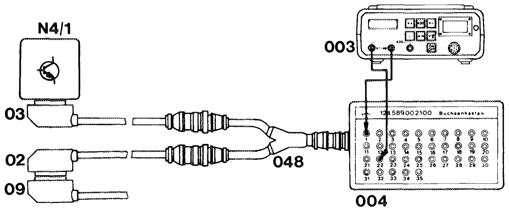
P30-0019 -53A
02 Test cable 645 589 02 63 00 003 Multimeter
03 Test cable 645 589 03 63 00 004 Contact box 124 589 00 21 00
09 Vehicle wiring harness (electronic accelerator 048 Test cable 645 589 00 63 00 control unit) N44 Electronic accelerator control unit
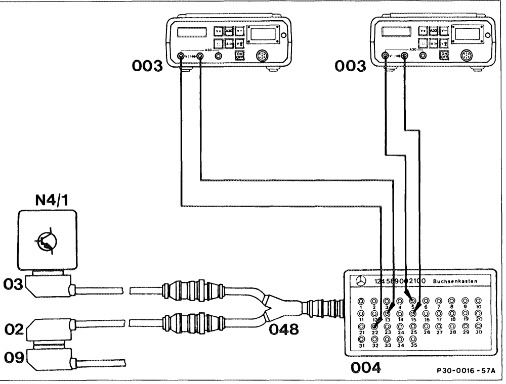
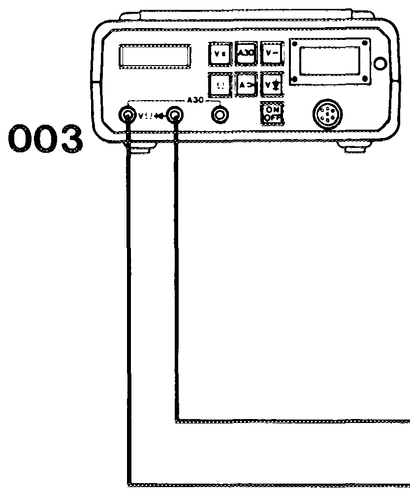
02 Test cable 645 589 02 63 00 003 Multimeter
03 Test cable 645 589 03 63 00 004 Contact box 124 589 00 21 00
09 Vehicle wiring harness (electronic accelerator 048 Test cable 645 589 00 63 00 control unit) N4/1 Electronic accelerator control unit
Test requirement
Accelerator control linkage correctly set and checked for ease of movement (30-305). Battery voltage at least 11 Volts.
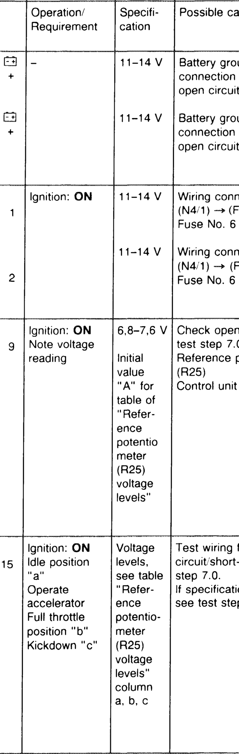
cause/Remedy
(G1) loose,
(G1) loose,
connection (F1)
connection (F1)
circuit, see
potentiometer
(N4/1)
for open see test
not reached, 3.3

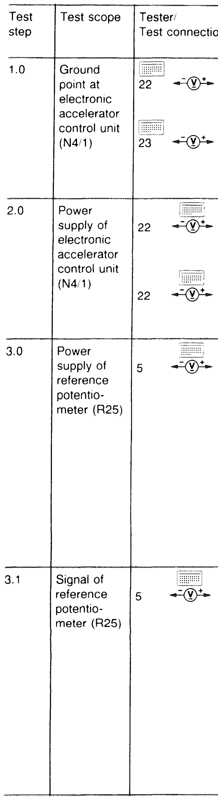
| Test scope’ Tester/ | Operation/ | Possible cause/Remedy | |
| Test connection | Requirement | cation | |

Reference Ignition: ON
Test wiring for open potentio- 22 =v)* 13 Idle speed Circuit/short-circuit, see test step 7.0 meter (R25) position switch point safety Slowly deflect switch accelerator pedal until shift point occurs
Note voltage ! reading at shift Reference potentiometer Ta oint
5 +O 15 ° faulty
Second multimeter to contact box
Reference Ignition: OFF Reference potentiometer potentio- Detach faulty meter (R25) 1 (=n) 9 electronic accelerator
5 (my 22 control unit _ connector.
5 15° Ignition: ON Deflect accelerator pedal as far as full throttle stop
Actuator Ignition: ON Test wiring for open (M16/1) 6 26 Note voltage circuit/short-circuit, see test power reading step 8.0. supply Electronic accelerator potentiocontrol unit faulty meter
| Tester/ | Possible | |
| Test connection | cation | |

Test wiring for open Circuit/short-circuit, see test 28 step 8.0. If specification is not reached, see test step 4.4
Test wiring for open circuit/short-circuit, see test 29 step 8.0
Actuator faulty =O 28
Second multimeter contact box
Test wiring for open circuit, N4/1 see test step 4.5. D.C. 21 3 If specifications are not reached, see test step 4.4 rod

Tester/ Test scope Test connection
Actuator (M16/1)
Actuator (M16’1) 3.
Backup light switch (S16/1)
Fuel pump relay (N16/4)
short ground.
Y
| Tester/ | Operation/ | Possible cause/Remedy |
| Test connection | Requirement | |


at <500 kQ renew wiring R25x1
Ignition: OFF
Detach harness —{t owawrawnl NW eee 1 connector at electronic 1 accelerator 1 control unit. 1 + Separate plug and 2 + ’ unit 2 connections at + ’ reference 2 + ’ 3 potentiometer and actuator 3 6
Ignition: OFF at <500 kQ renew wiring M16/1x Detach harness A OVOMVaATAVOGAwVaMAON! NY \ efi fa fe fa fa fe fa qa fo fe fe qa fe ta qa qa fa qa fa AOanaik = =A = AH = PRWWWOWNMNNNNDA [+ [+ [+ [+ J+ [+ [+ T+ T+ [+ T+ [+ T+ T+ T+ T+ [+ T+ TG + connector at electronic accelerator and control unit. unit Separate plug connections at reference potentiometer and actuator
+ ’
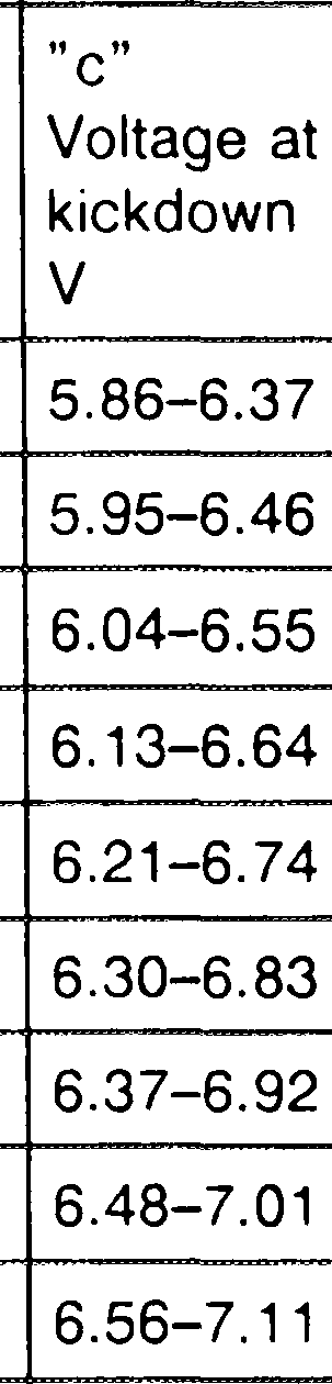
Potentiometer voltage Voltage in idle Voltage in full Voltage at safety switch supply speed position throttle position switch point Vv Vv Vv Vv
| a |0.50–0.56 | §.86–6.22 | OO 0.86–1.13 | |
| 0.51–0.57 | 5.95–6.32 | 0.87–1.14 | |
| a | 0.52–0.58 | _ | |
| 0.53–0.58 | |||
| 0.530.859 | |||
| 0.54–0.60 | |||
| 056-061 | |||
| 0.56–0.62 | |||
| _ | 0.56–0.63 | i | |
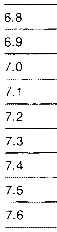
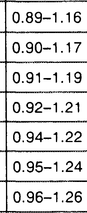
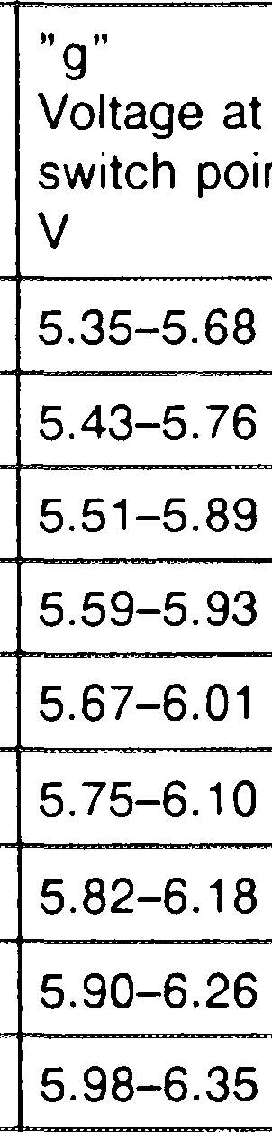
Voltage levels electronic accelerator actuator (M16/1)
| „By Potentiometer voltage supply V | fuil throttle | safety switch | |
| 68 | | 0.61–0.75 5.35–5.68 | ||
| 6.9 | _ | ||
| 7.0 | (0.63–0.77 0 5.51–5.89 | ||
| 74 | (0.64–0.78 (559-593 | ||
| 7.2 | 0.65–0.79 = 5.67–6.01 | ||
| 7.3 | 066-080 iS 75-6100 | ||
| 7.4 | 0.67–0.81 §.82–6.18 | ||
| 75 | = | ||
| 76 | 0.69–0.84 a 5.98–6.35 a | ||
N4/1
R25 x
P30-0087–59
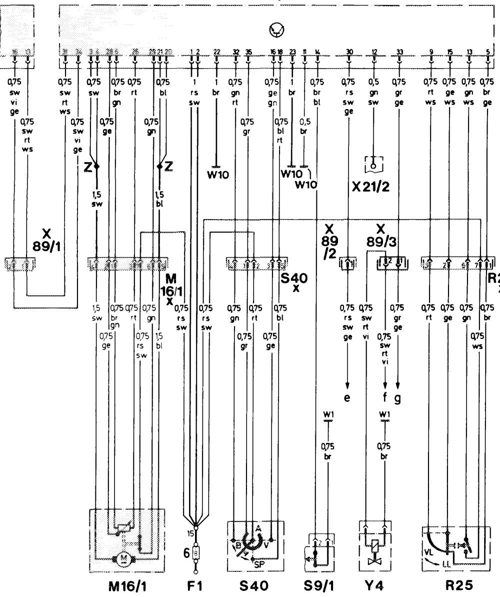
Fi Fuse and relay box X89/1 Connector, electronic accelerator control G1 Battery unitv/ASR (2-pole) M16x1 Connector, cruise control actuator X89/2 Connector, electronic accelerator control M16/1 Electronic accelerator actuator unit/engine harness (2-pole) N4/1 Electronic accelerator control unit X89/3 Connector, electronic accelerator control N30/1 ABS/ASR control unit unit/automatic transmission (2-pole) R25 Accelerator pedal position sensor Y4 Switchover valve (transmission mode) R25x1 Connector, accelerator pedal position sensor Zz Connector sleeve (solder joint in harness) so/1 Stop lamp switch (4MATIC/ASD) S40 Cruise control switch e Fuel pump relay, contact 9, terminal 15 V Decelerate/set f Economy mode switch, contact 2 B Accelerate/set g Starter lockout and backup light switch, contact 4 SP Resume A Off S40x1 Connector, cruise control switch W10 Ground, battery X21/2 Terminal block, stop lamp switch/electronic speedometer
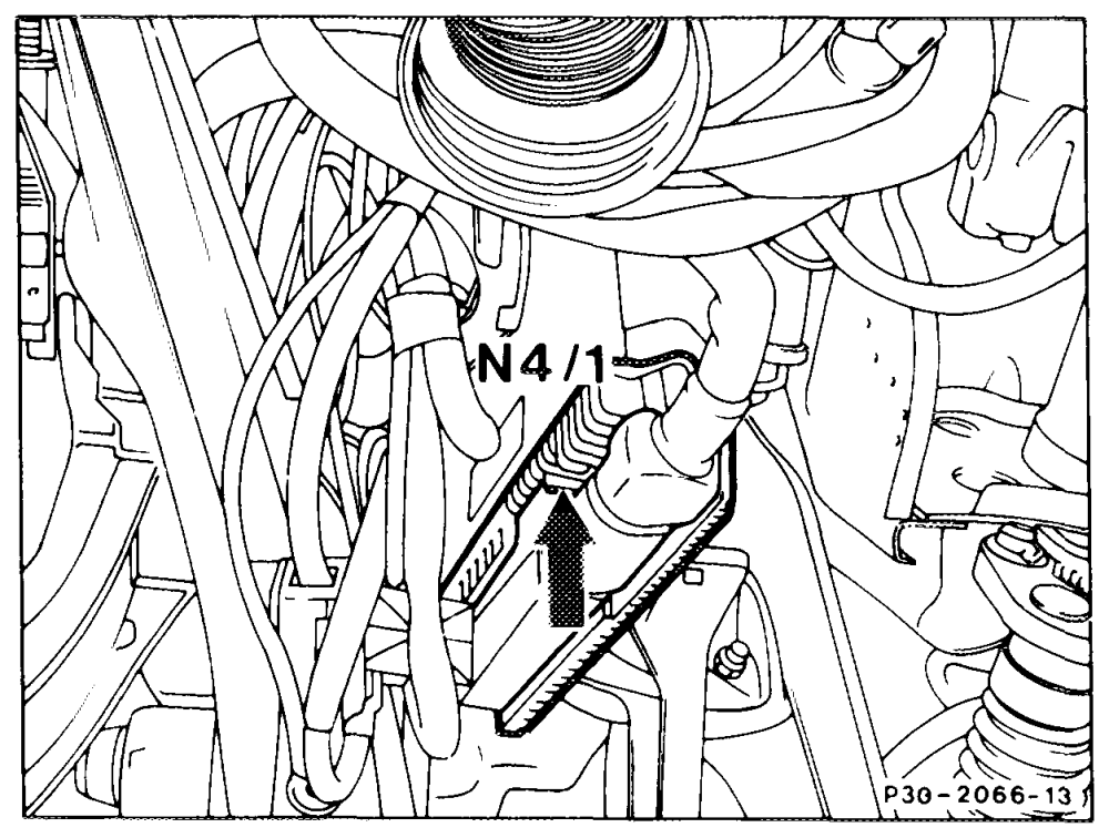
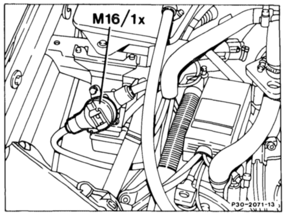
Arrangement
The electronic accelerator control unit (N4’1) is located below the instrument panel, above the pedals.
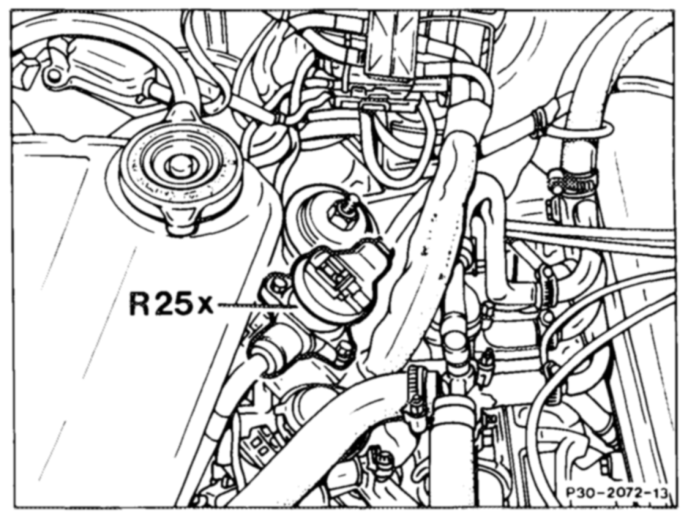
The cruise control actuator connector (M16x1) is located ahead of the expansion tank (cover removed).
The electronic accelerator reference potentiometer connector (R25x1) is located next to the expansion tank (cover removed).