Testing cruise control (vehicles with ASR)
WIS 30-370
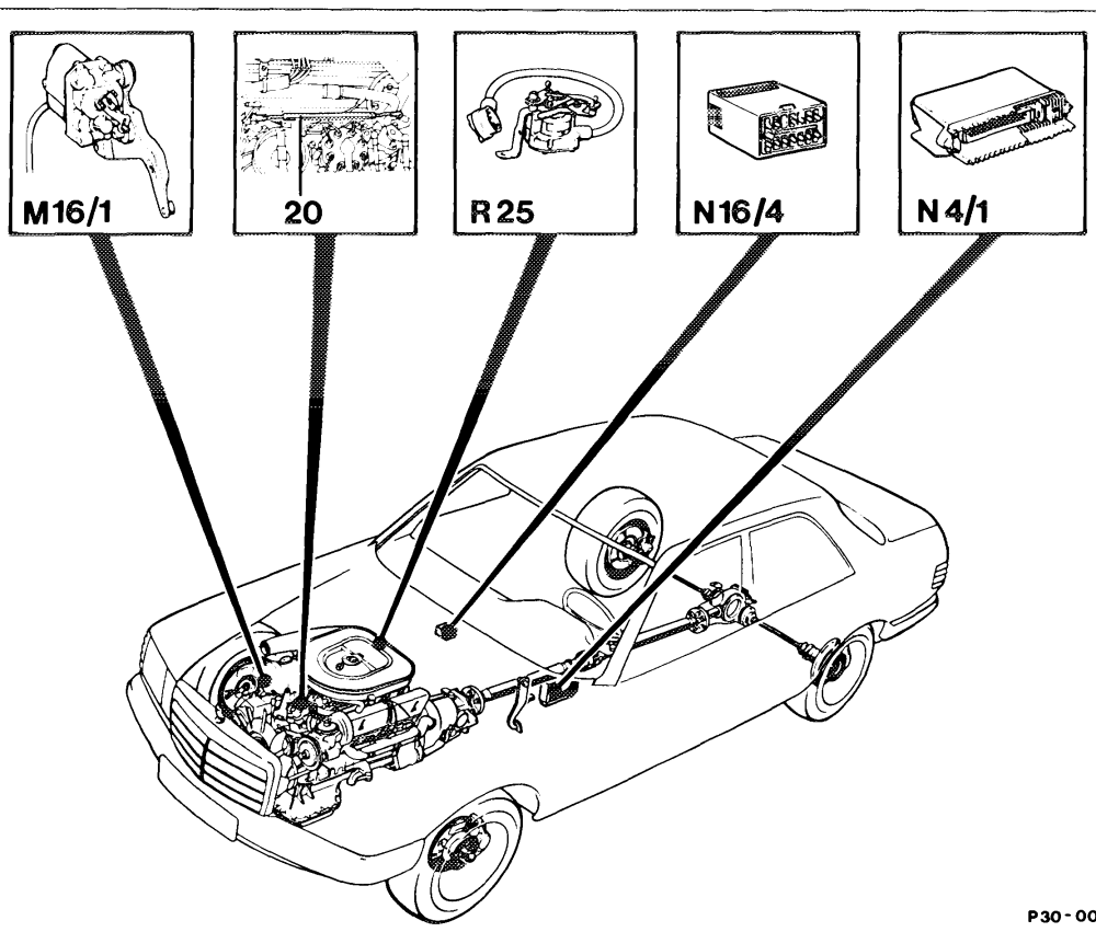
0098 – 57
M16/1 Electronic accelerator actuator R25 Accelerator pedal position sensor Nai Electronic accelerator control unit N16/4 Fuel pump relay with kickdown cut-out 20 Idle travel rod (redundancy rod)
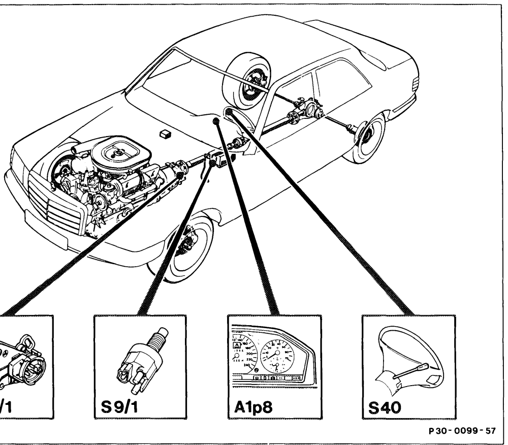
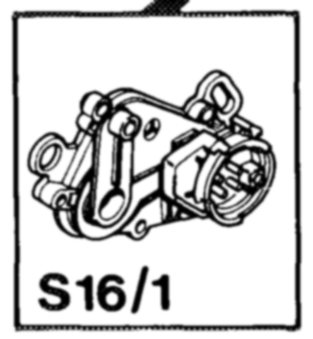
Starter lockout and backup light switch S16/1 A1p8s Electronic speedometer S40 Cruise control switch sot Electronic accelerator control unit
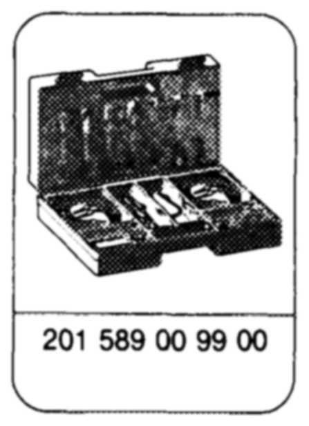
Special tools
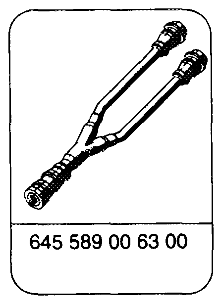
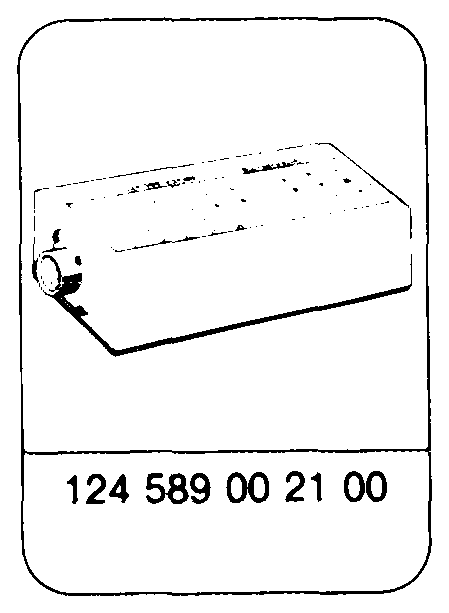
Commercial tools
e.g. Sun, DMM-5 Multimeter e.g. Sun, DTR-8416. Function generator
Explanation of symbols
(SFIS) Multimeter =-@)*= Multimeter, resistance mode Contact box =*> Multimeter, D.C. voltage mode Function generator Function generator, square-wave Battery signal —¢ Contact _ Connector —(se—a=a)- Jumper Ground ak
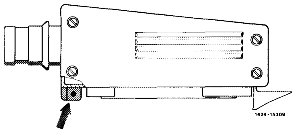
The stud (arrow) on the test cable 645 589 02 63 00 must be sawn off.
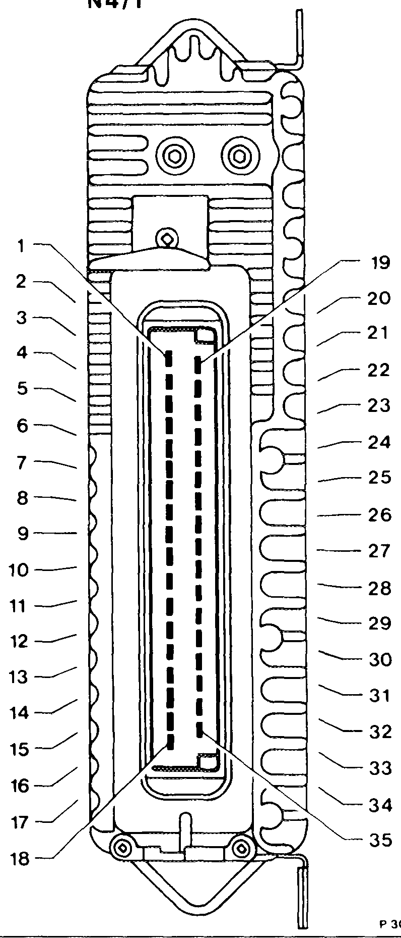
Electronic accelerator actuator (motor) Electronic accelerator actuator (motor) Reference potentiometer (ground) Electronic accelerator actuator potentiometer (ground) Do not create contact! Engine 116, 117, 119: not assigned Engine 103, 104: idle speed switching signal to CIS-E contro} unit Reference potentiometer, voltage supply ( +) Not assigned 10 Battery ground (W10) 1 Electronic speedometer speed signal 12 Safety switch, reference potentiometer 13 Stop light switch 14 Reference potentiometer (wiper signal) 15 Cruise control switch (Decelerate, Set) 16 Not assigned 17 Cruise control switch (Resume) 18 Do not create contact! 19 Electronic accelerator actuator (motor) 20 Electronic accelerator actuator (motor) 21 Battery ground (W10) 22 Battery ground (W10) 23 Not assigned 24 Not assigned 25 Electronic accelerator actuator, potentiometer 26 (voltage supply) Not assigned 27 Electronic accelerator actuator, potentiometer 28 (wiper signal) Electronic accelerator actuator (safety switch) 29 Fuel pump relay, terminal 15, contact 9 or engine 30 systems control unit, terminal 15u, contact 10 To ABS/ASR control unit (throttle valve actual value) 31 P30-0017–17 Cruise control switch (Accelerate, Set) 32 Starter lockout and backup light switch, driving stage „R” 33 From ABS/ASR control unit (throttle valve set value) 34 Cruise control switch (Off) 35
P30-0019 -53A
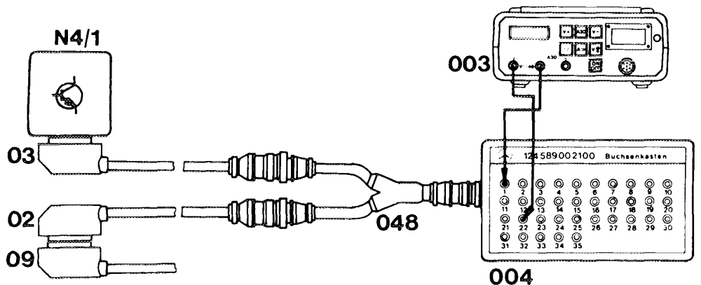
02 Test cable 645 589 02 63 00 004 Contact box 124 589 00 21 00
03 Test cable 645 589 01 63 00 003 Multimeter 0g Vehicle cable harness (electronic accelerator control unit) N4a/1 Electronic accelerator control unit 048 Test cable 645 589 00 63 00
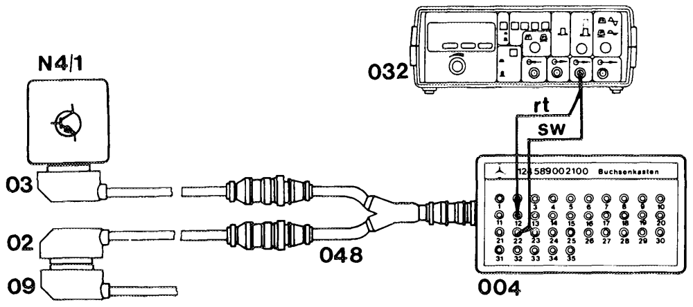
Connection diagram with function generator for cruise control test routine
P30-0020-53A
02 Test cable 645 589 02 63 00 004 Contact box 124 589 00 21 00
03 Test cable 645 589 01 63 00 003 Multimeter
09 Vehicle cable harness (electronic accelerator control unit) N41 Electronic accelerator control unit 048 Test cable 645 589 00 63 00
Test requirement

Accelerator control adjusted and checked for ease of movement. Battery voltage at least 11 Volts.
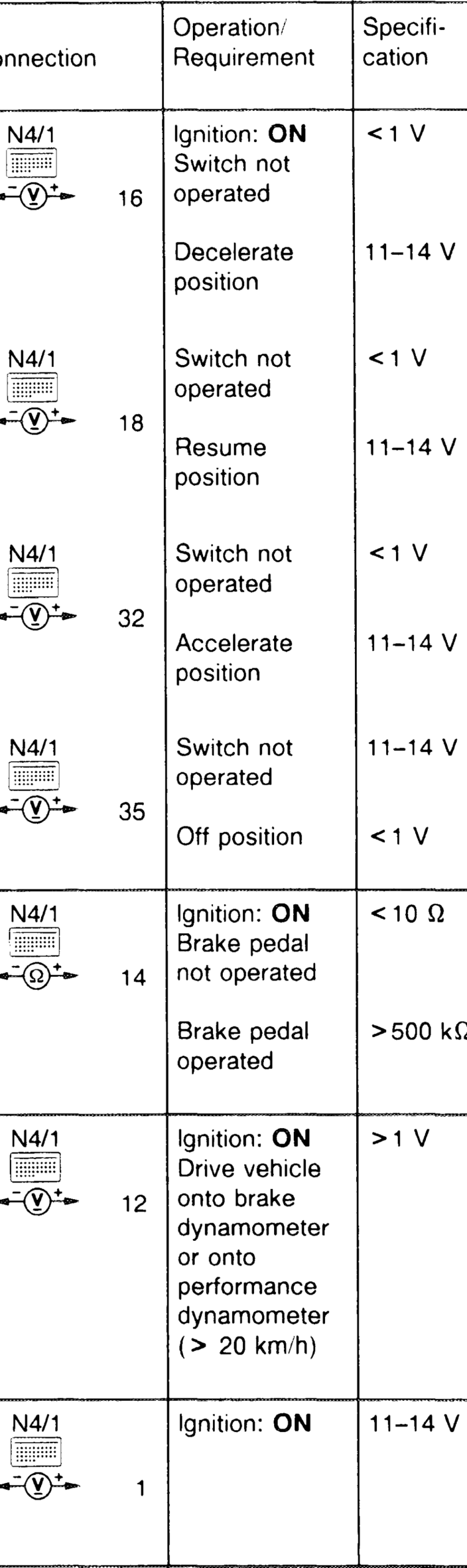
__ Tester/ Possible cause/Remedy Test
Test wiring for open/short circuit.
22 Cruise control switch (S40) faulty
22
22
22
| 22 | Test wiring for open/short circuit Stop light switch faulty |
| 22 | Test wiring for open/short Circuit Electronic speedometer faulty |
| 11 | Test wiring for open/short circuit Test wiring for correct assignment |
30.0714 – 3706

Actuator Electronic accelerator N4/1 EERE control unit (N4/1) moves 22 ~@*. 12 toward full load „1”
Hz
Actuator moves toward idle speed
Actuator must move into idle speed position
Actuator must move into specified position
brake Actuator must move into idle position