Greasing accelerator control linkage and shafts (continued)
WIS 30-350
A. General
The acceleration slip control (ASR) is an automatic system for improving starting-off and accelerating capability as well as driving stability.
ASR is the logical further development of the anti-lock system (ABS). Whereas ABS prevents the wheels from locking when braking and thus maintains steering control and driving stability when braking the vehicle, ASR prevents the driven wheels from spinning when moving off and accelerating. The result is optimal driving stability with enhanced traction. The ABS basic components are supplemented for ASR by a hydraulic unit with expanded functions, a pressure supply unit, a fourth rotational speed sensor, enlarged electronic control and the electronic accelerator with control unit, potentiometer and electronic accelerator actuator.
In addition, the cruise control system is contained in the control unit of the electronic accelerator.
@ Improves starting-off and acceleration
capability as a result of enhanced traction, particularly beneficial on road surfaces and curves with differing levels of adhesion.
@ Enhances active dynamic safety as it is
sufficient to have only a single wheel which is not spinning to achieve optimal traction with no loss of cornering control.
e Automatically adapts engine torque to
respective adhesion capability between wheel and road surface if the driver accelerates too sharply.
e A function display indicates that the ASR
control has been activated and signals to the driver that he is approaching the physical limits of the vehicle.
Driving with ASR
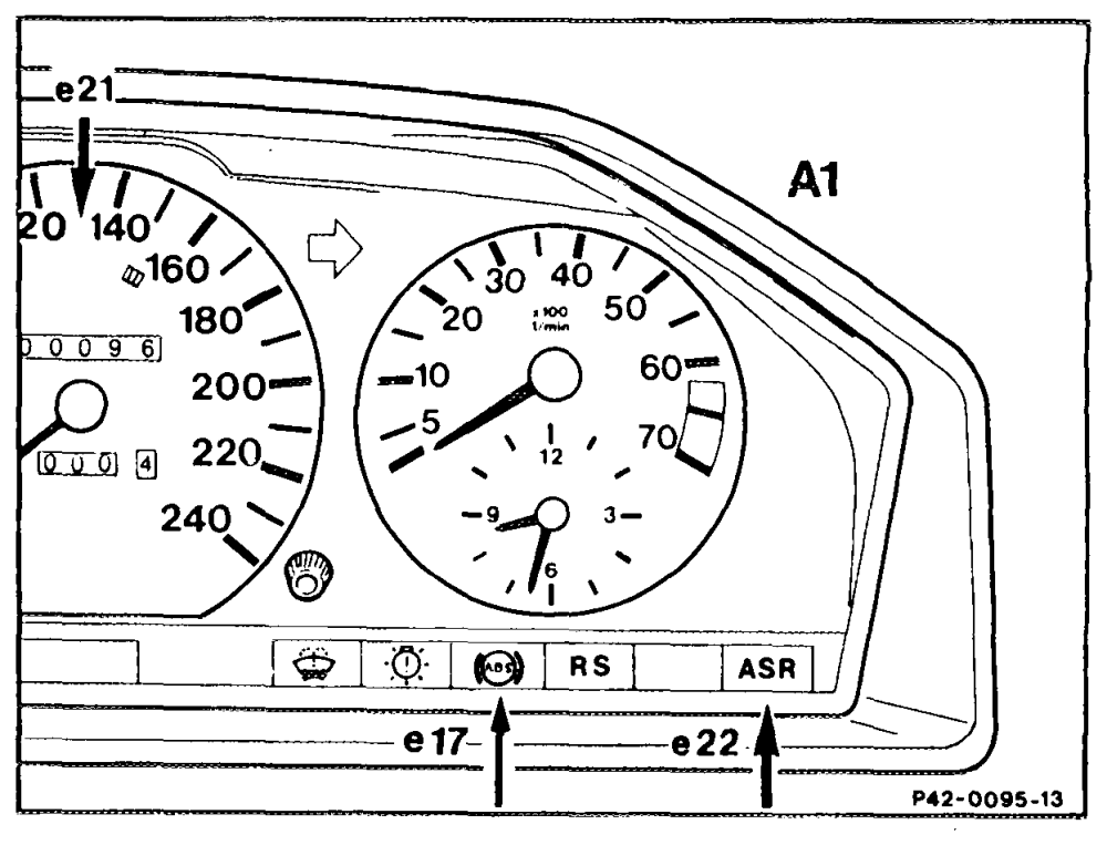
The instrument cluster contains displays with various symbols for the ASR.
A1e17 ABS indicator lamp Ate21 ASR function display Ale22 ASR indicator lamp
Switching on ignition
When ignition is switched on (ignition starter switch “position 2″), the function display and the indicator lamps in the instrument cluster light up (bulb check) and go out once the engine is running.
Driving
When driving, the function display lights up as soon as the ASR is operating. The function display remains on for approx. 1 s after end of ASR control mode. If the ASR control is activated only for a very short moment, the function display does not light up.
Control mode
The function display indicates that the ASR control has been activated and signals the driver that he is approaching the physical limits of his vehicle. This enables him to adapt his driving style better to road conditions.
Check
if the ASR indicator lamp lights up when the engine is running, this indicates a fault in the ASR or in the electronic accelerator. The ASR system is inoperable although the ABS function is retained. if the fault occurs in the electronic accelerator, it is possible to continue driving with reduced engine output. The driver notices this from the altered operating forces of the accelerator pedal. If the ASR and ABS indicator lamps light up when the engine is running, this indicates a fault in the ABS which also involves the ASR being deactivated as well, or in the ASR which also affects the ABS system. Both systems are switched off.
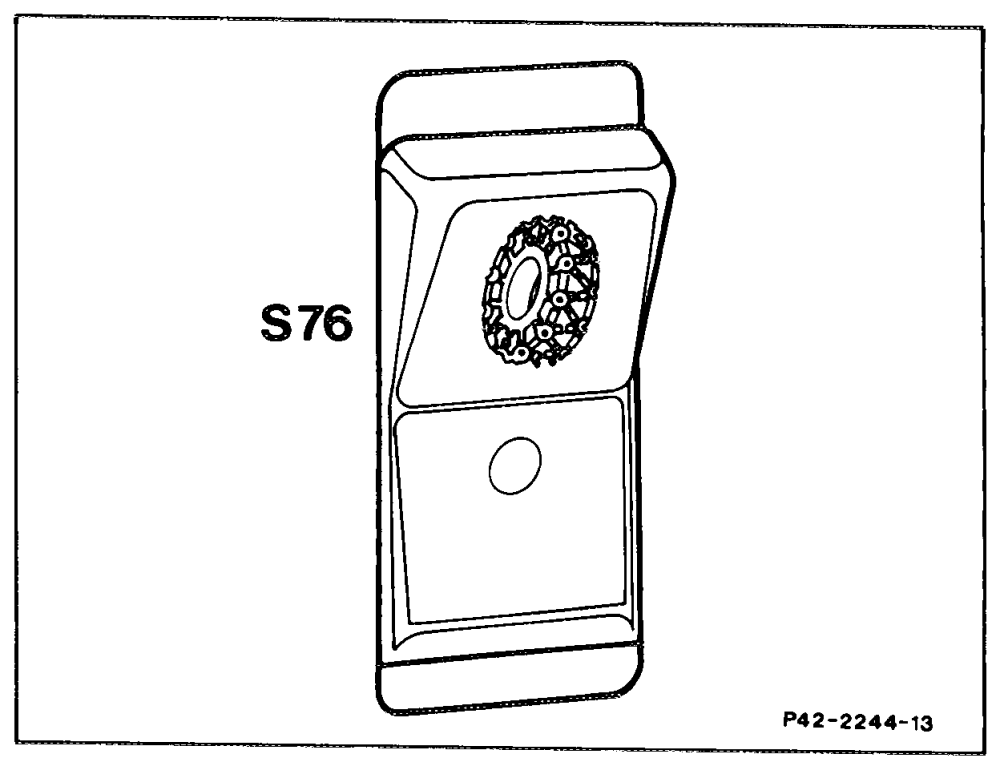
Snow chain switch (S76)
(ASR slip threshold control with indicator lamp)
The responsive, stability-oriented control of the ASR may have a detrimental effect on startingoff behavior in deep snow and with snow chains fitted. For this reason, a special control logic has been programmed into the system for the starting-off range in appropriate situations, which the driver can select by pressing the snow chain switch. When the snow chain switch is operated, the indicator lamp in the switch lights up. After approx. 50 ms continuous ASR control mode, a higher drive slip limit is permitted at the wheels to enable the vehicle to get free in the situations indicated above. As this higher slip would have a negative effect on driving stability, particularly at higher speeds, it remains limited to the speed range <40 kmvh. The higher drive slip remains stored up to 60 km/h and is automatically reactivated if vehicle speed drops below <40 kmih. Once vehicle speed exceeds 60 km‘h, the stored higher slip is erased and the indicator lamp in the switch goes out.
Arrangement of components
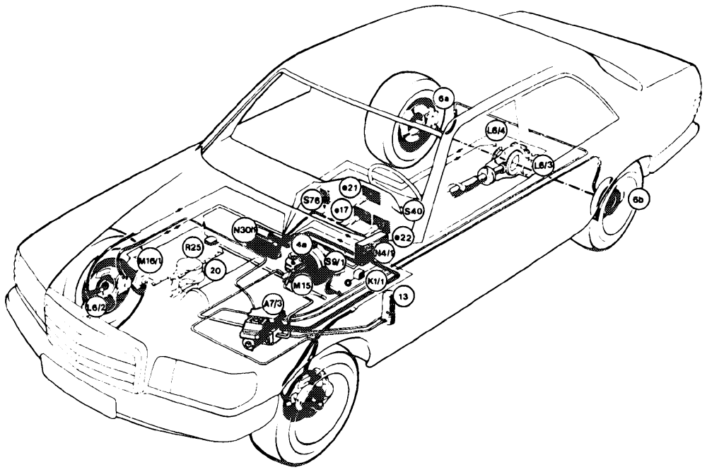
P42-0097–57
Electrics/Electronics
Hydraulics
Ate17 ABS indicator lamp ABS hydraulic unit for ASR A7 Ale21 ASR function display ASR hydraulic unit A7/3 Ale22 ASR indicator lamp M15 Boost pump K1/1 Overvoltage protection relay Brake fluid reservoir 4a K20 Boost pump relay 13 Pressure accumulator L6e/1 Left front axle speed sensor Rear brake caliper with wear indicator 6a/6b L6/2 Right front axle speed sensor L6/3 Left rear axle speed sensor
Mechanical parts
L6/4 Right rear axle speed sensor 20 Idle travel rod (redundancy rod) M16/1 Electronic accelerator actuator Na/1 Electronic accelerator control unit N30/1 ABS/ASR control unit R25 Electronic accelerator potentiometer sot Stop light switch S40 Cruise control switch S76 Snow chain switch (slip threshold selector) with indicator lamp
Driving torque control loop
The speeds of all the wheels are detected in the ABS’ASR control unit and processed. If the In order to reduce excessive driving torque for optimal traction, an exchange of signals ABS/ASR control unit detects from the speed takes place along the link between the signals that one or both driven wheels are ABS/ASR control unit and the electronic tending to spin, the ASR control mode is activated with the brake torque control loop and the accelerator control unit. The throttle valve position is reduced by the driving torque control loop. actuator in contrast to the accelerator pedal position input by the driver. A constant The following procedures are then performed: check is performed in the ABS/ASR control unit as to whether e.g. the control functions
e Brake torque control loop
The spinning driven wheel is braked by the can be canceled as a result of a sudden relevant whee! brake until it has reached the improvement in road surface adhesion in order to again permit the driving torque most favorable drive slip range. This enables the other wheel to be optimally input by the driver through the accelerator driven (locking differential effect). The spinpedal at the earliest possible moment. ning wheel is braked by part of the highly pressurized brake fluid in the pressure A distinction is made between two control ranges in the ASR control mode: accumulator flowing out of the accumulator through the ABS and ASR hydraulic units Control mode for one spinning driven wheel into the brake caliper (pressure buildup). A solenoid valve modulates the pressure flow and driving speeds <40 knvh in which the in the brake caliper during the brake torque control is oriented to the driven wheel which is still gripping. In this case, the slip control, in pressure buildup, pressure holding and pressure reduction. During the threshold of the driving torque control is relatively high. The emphasis in this case is pressure buildup phase, the brake fluid volume is pumped out of the brake caliper on achieving maximum traction. through the return pump into the pressure Control mode if both driven wheels are accumulator. This control sequence is performed individually for each wheel brake of spinning or at driving speed <40 km/h with the driven wheels. the control oriented to the spinning driven wheel. The slip threshold of the braking torque control in this case is still above that for the driving torque control. Consequently, the emphasis is on achieving maximum driving stability.
C. Driving torque control loop
The driving torque control loop is based on the electrical / electronic components of the ABS/ASR and is supplemented by the electronic accelerator. The electronic accelerator is composed of the following electrical / electronic and mechanical components:
Electronic accelerator potentiometer (R25) Electronic accelerator actuator (M16/1) Electronic accelerator control unit (N4/1) Accelerator control linkage and accelerator pedal
e@ idle travel rod (redundancy rod)
The speed signals of the speed sensors are constantly processed in the ABS circuits and ASR microcomputers in the ABS/ASR control unit to form the following variables:
e Drive slip
e Acceleration
e Driving speed (front wheel)
lf the variables calculated exceed certain given specified values, the ABS/ASR control unit signals the electronic accelerator control unit to throttle back. As a result, the electronic accelerator control unit and thus the throttle valve are controlled irrespective of the amount by which the accelerator pedal is depressed.
is activated and signals to the driver that he is approaching the physical limit of his vehicle.
The function of the ABS is not impaired by the ASR as an ASR control mode is interrupted by braking.
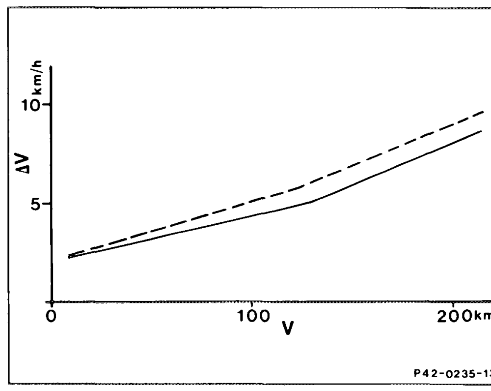
Depending on the speed driven, the braking torque control begins as soon as the differential speed between front and rear wheel (Av) rises beyond the slip threshold of the braking torque control. Braking of the relevant rear wheel is controlled by building up pressure, holding pressure and reducing pressure in the corresponding rear wheel brake. Once the differential speed (Av) again drops below the slip threshold, the system switches over to pressure buildup for a given time interval.
Slip thresholds
Speed Differential speed between front and rear wheel
Braking torque control
Driving torque control
Irrespective of road condition and direction, an If both driven wheels are spinning or at vehicle ASR control mode proceeds as follows: speeds >40 km/h, the driving torque control is superimposed on the braking torque control. If one driven wheel is spinning and the driving The ABS/ASR control unit detects an impermissibly high slip and passes a signal to the speed is <40 km/h, the braking torque control is superimposed on the driving torque control. In electronic accelerator control unit. The throttle this case, the braking torque control is activated valve is moved by the electronic accelerator first. The ABS/ASR control unit detects an imactuator against the accelerator pedal position permissibly high slip and passes a signal to the input by the driver. As a result, the driving solenoid valves in hydraulic unit. Thereupon, torque is reduced to the point where no slip accumulator pressure flows into the appropriate which may impair driving stability can occur at brake caliper so that the relevant wheel is the driven axle. The driver may detect the braked. As a result, the wheel running on the movement of the throttle valve by brief changes road surface offering better adhesion is supplied in the accelerator pedal forces. The control with torque through the differential. If the driver movement is continued until a wheel has depresses the accelerator to full throttle, the dropped below the critical slip threshold. The spinning wheel moves into a higher slip range. remaining control cycle is then the same as for The driving torque control is activated at a single spinning driven wheel. approximately twice the slip of the braking torque control. The ABS/ASR control unit passes a signal to the electronic accelerator control unit. The throttle valve is now moved by the electronic accelerator actuator against the accelerator pedal position. The driving torque is reduced. As soon as the slip has dropped below the lower slip limit, the throttle valve is slowly opened. This enables the maximum possible driving torque to be transmitted to the road. If the road conditions change, a renewed control cycle is started.
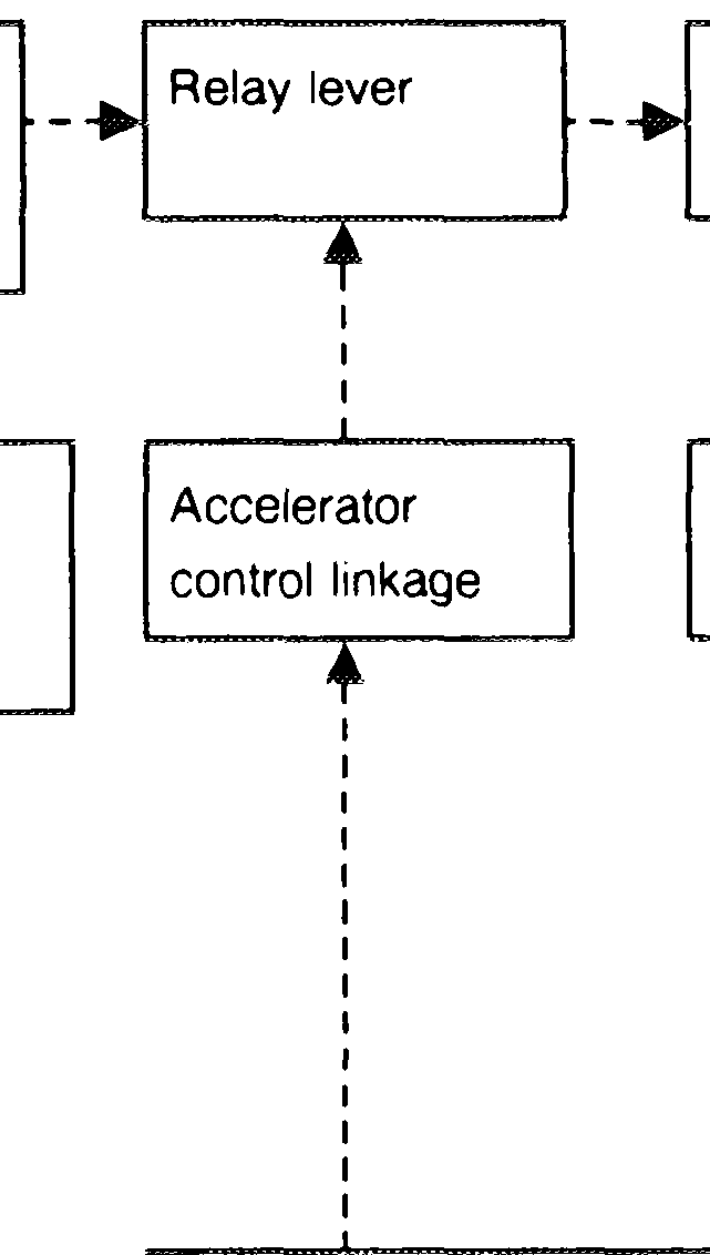
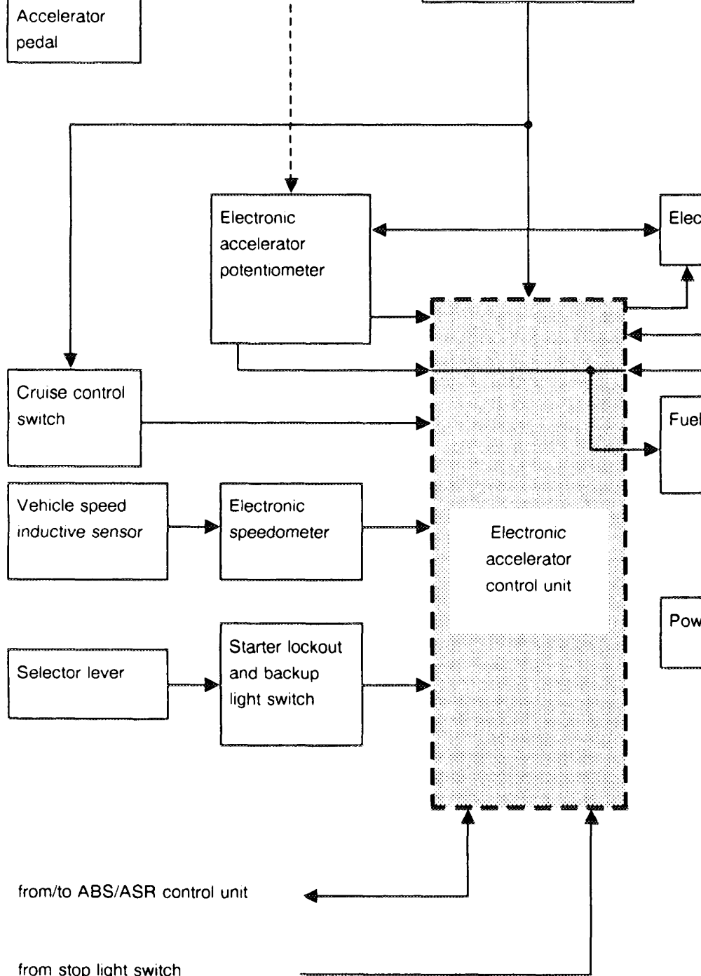
Fulcrum and Idle travel rod Accelerator accelerator control (redundancy rod) control linkage lever a 4 —
_y a
t Power supply through Throttle valve
t ignition starter switch
’ ee \
Electronic accelerator actuator
oe
_
a pump relay Fuel pumps
a ah
Te
oe ee supply TD/TN signal or start signal – _ ~
electric circuits
mechanical transmission
D. Electronic accelerator components

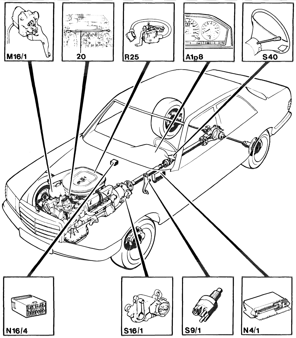
P30-0076 -61
Electronic accelerator potentiometer A1p8 Electronic speedometer R25 M16/1 Electronic accelerator actuator $9/1 Stop light switch Starter lockout and backup light switch N4/1 Electronic accelerator control unit S16/1 N16/4 Fuel pump and kickdown shutoff relay $40 Cruise control switch Idle travel rod (redundancy rod) 20
The electronic accelerator actuator thus All the control processes as well as the mechanical adjusting movements are performed assumes a position corresponding to the set with the electrical /electronic components in value. The output lever of the electronic accelerator actuator is connected to the throttle combination with the mechanical components. The electronic components are supplied with valve by an accelerator control linkage. The opening angle of the throttle valve corresponds the necessary voltage through unprotected terminal 15 in the fuse box. The following to the input set value, as a result of which the components supply signals to the electronic engine transmits a certain torque to the driven accelerator control unit: wheels. If the entered set value (accelerator pedal Electronic accelerator potentiometer deflection) is higher than the driving torque Electronic accelerator actuator which can be transmitted to the road, this would ABS/ASR control unit result in the wheels spinning (slip). This slip is Starter lockout and backup light switch detected by the ABS/ASR control unit and a Cruise control switch signal (throttle valve set value) is passed to the Electronic speedometer electronic accelerator control unit. As a result, Stop light switch the electronic accelerator actuator and thus the throttle valve can be closed against the The input signals are processed and monitored adjusting movement of the accelerator pedal. If in the electronic accelerator control unit. The the throttle is excessive, the driving torque is reduced until the slip drops below a fixed value. following components are activated with the output signals: With the electronic accelerator, it is possible to move the throttle valve between idle speed and
e Electronic accelerator actuator
full throttle or with the ASR to close it in the idle
e ABS/ASR control unit
direction. If there is excessive driving torque at
e@ Fuel pump relay
the driven wheels, the idle travel rod enables the throttle valve to be moved against the When the ignition is switched on, the electronic accelerator pedal position. The idle travel rod accelerator is activated. The position of the (redundancy rod) is an emergency driving accelerator pedal (set value) is signaled through device which enables the vehicle to continue to the electronic accelerator potentiometer to the be driven at reduced engine output should the electronic accelerator control unit. An output electronics fail. In addition, a cruise control signal for controlling the actuator is assigned to system is contained in the electronic accelerator this set value in the electronic accelerator control unit. control unit.
Features:
e Throttle valve is always moved by the
electrical / electronic device.
e Cruise control system is integrated in the
electronic accelerator control unit. e@ The vehicle can continue to be driven at reduced engine output in the event of a failure of the electrics ‘ electronics.
Block diagram of electronic accelerator
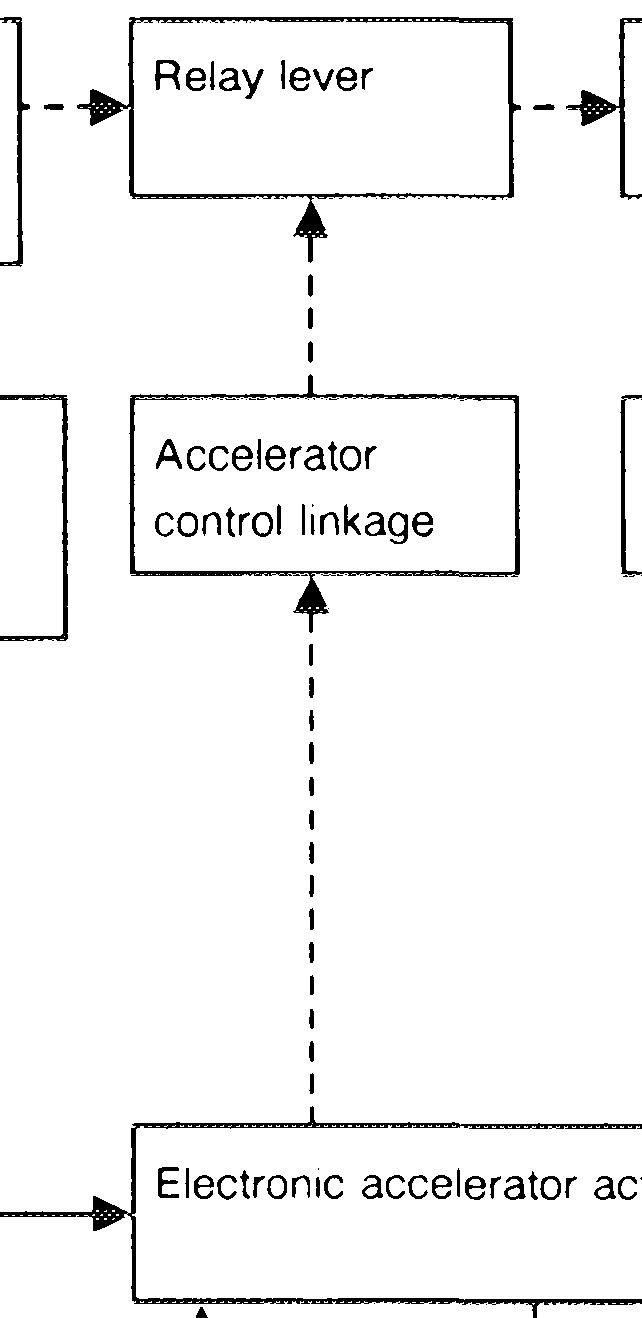
Fulcrum and Idle travel rod Accelerator accelerator control (redundancy rod) control linkage lever 1 ’ v ’ i
1 Power supply through Throttle valve
t ignition starter switch
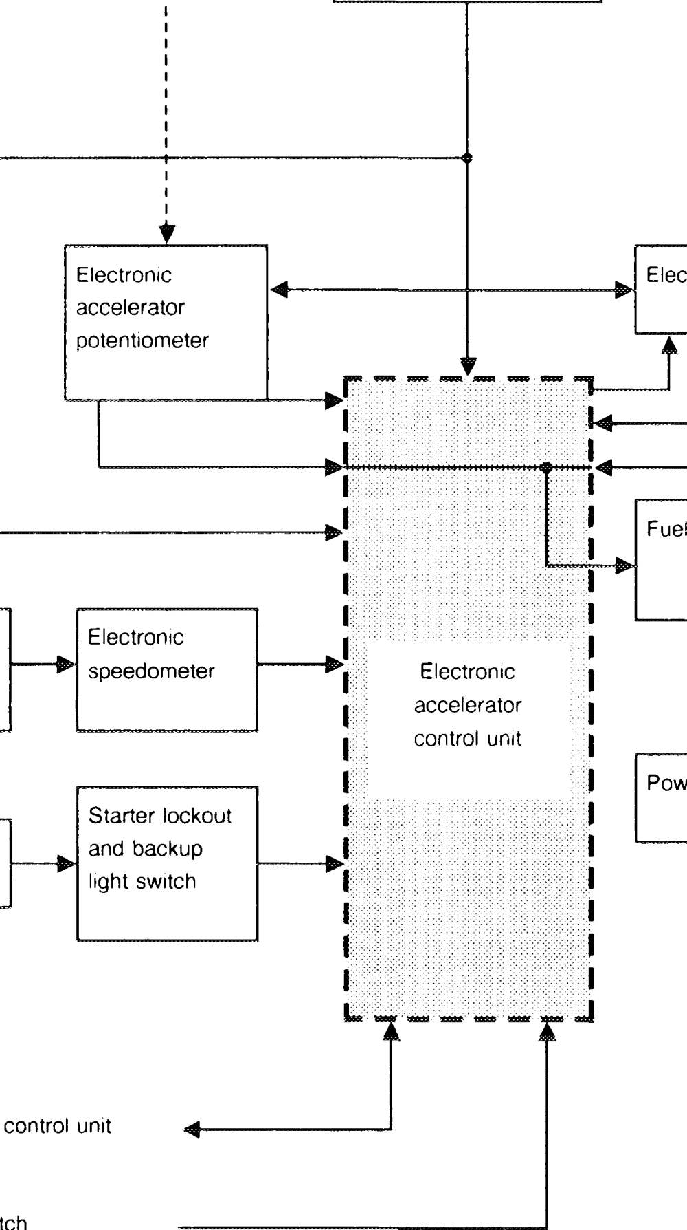
\ \ 1
actuator
a
— v a oo Cruise control _ ae switch pump relay Fuel pumps >
__|
Vehicle speed a 4
inductive sensor ~ ~
oe supply TD signal or ee start signal Selector lever
a
from/to ABS/ASR
from stop light switch a
electric cables
-2o– eee mechanical transmission
F. Ignition starter switch „position 2”
When the ignition is switched on (ignition starter A voltage signal is likewise input by the switch „position 2”), the electronic accelerator potentiometer of the electronic accelerator is activated. Power is supplied to the electronic actuator (actual position of throttle valve). Both accelerator control unit, electronic accelerator signals are compared in the position controller of the electronic accelerator control unit. If these potentiometer and to the electronic accelerator actuator. In addition, the fuel pump relay is signals vary, the actuator position is adapted to activated through the safety switch of the the set value (position of accelerator pedal). In electronic accelerator actuator (voltage at addition, when the ignition is switched on, an terminal 15). Voltage is supplied from it to the exchange of information occurs between the ABS/ASR control unit and the electronic fuel pumps for approx. 1 s. In addition, the cruise control switch is supplied with voltage accelerator control unit. through the ignition starter switch. The electronic accelerator control unit checks When the accelerator pedal is depressed, the whether the permissible throttle valve set value of the ABS/ASR control unit is below the set adjusting movement is transmitted through the accelerator control linkage, fulcrum and relay value input by the driver. If this set value is too large, the ABS/ASR control unit determines the lever to the electronic accelerator potentiometer. maximum possible throttle valve opening. Depending on the accelerator pedal position, the The signals from the electronic accelerator potentiometer inputs a corresponding voltage potentiometer, electronic accelerator actuator signal to the electronic accelerator control unit. and ABS/ASR control unit are checked by the monitoring device. The output stage is also checked by the monitoring device.
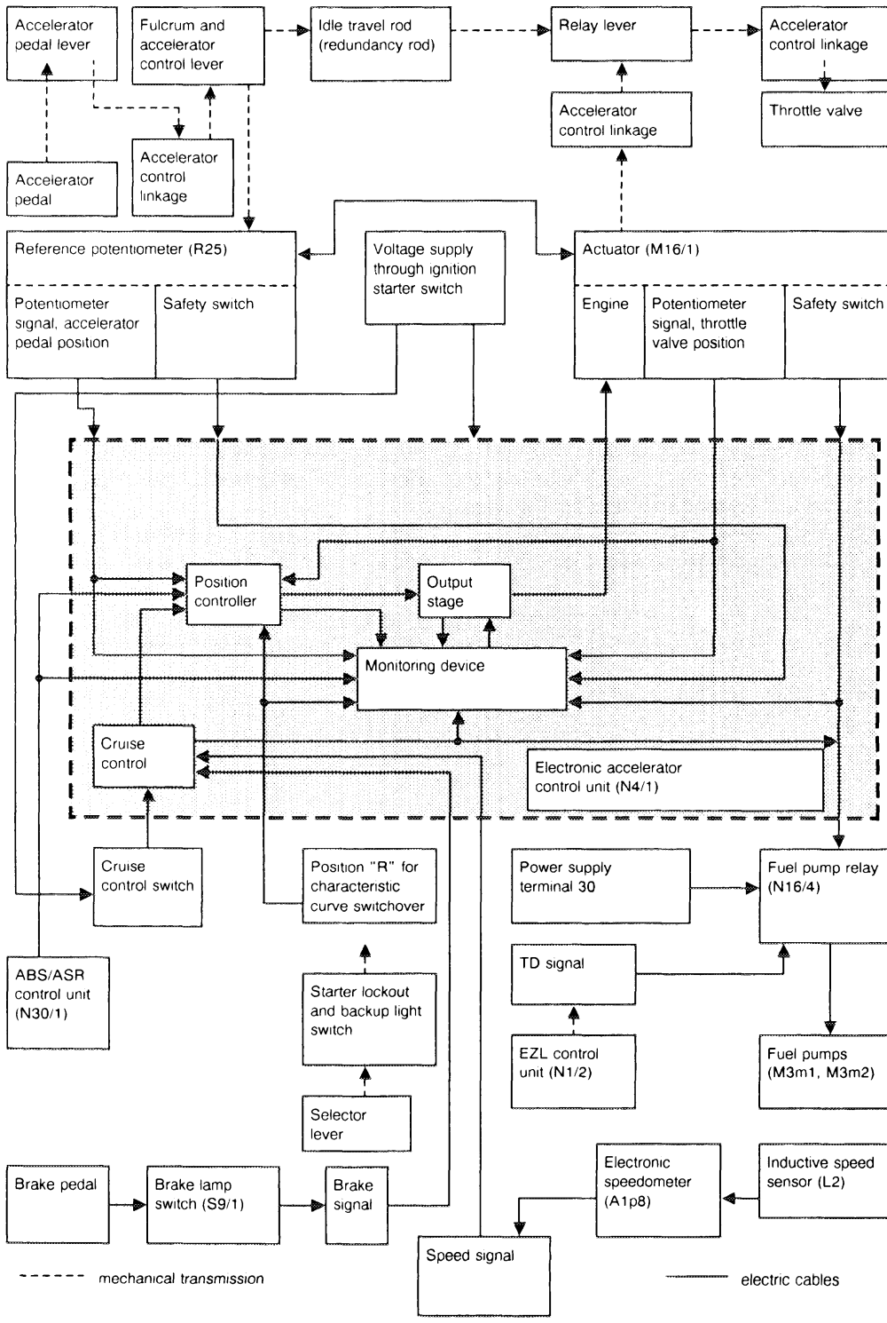
Block diagram of electronic accelerator ignition starter switch “position 2″/idling/driving
At idle speed, the electrical / electronic components are energized when the ignition starter switch is in “position 2″. The fuel pump relay (terminal 15) is energized through the safety switch of the electronic accelerator actuator. The relay picks up in combination with the TD/TN signal, as a result of which terminals 87 and 30 are linked. The fuel pumps are energized. The input signals from the reference potentiometer as well as from the electronic accelerator actuator are supplied to the electronic accelerator control unit. These signals are processed in the position controller and the D.C. motor of the electronic accelerator actuator is controlled accordingly. When the accelerator is depressed, the entire travel of the throttle valve can be utilized. Signals are exchanged between the ABS’ASR control unit and the electronic accelerator control unit as for ignition starter switch “position 2″.
Driving mode
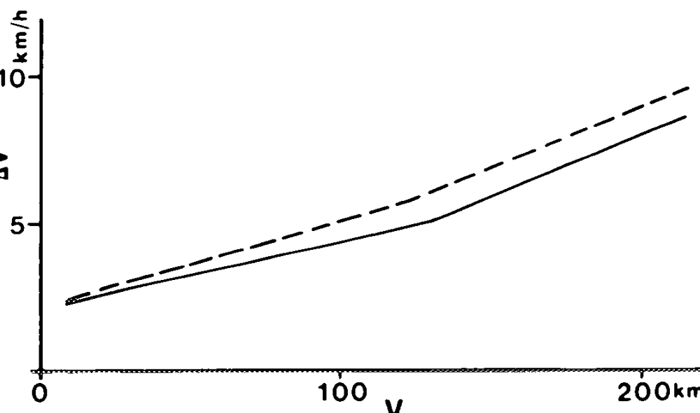
In the driving mode, the throttle valve is adjusted by the electrical ’ electronic and mechanical components. The desired driving speed in this case depends on the position of the accelerator > pedal. <= Dependent on the speed driven, the driving torque control is activated as soon as the differential speed (Av) rises above the slip threshold of the driving torque control. The driving torque is controlled by closing, holding and opening the throttle valve. Once the P42-0235–13 differential speed (Av) again drops below the slip threshold, the throttle valve is opened according Slip thresholds to the accelerator pedal input from driver.
v = Speed Av = Differential speed between front and rear wheel
a Braking torque control
Driving torque control
The cruise control is operational as soon as the The system remains operational after being switched off until the ignition is switched off. If, ignition is switched on. The vehicle must be traveling at a speed >40 kmh, however, before after depressing the brake or switching off the the cruise control can be activated. Once the system, the switch is moved to the position „Resume” at a vehicle speed above approx. vehicle is traveling at the desired speed, it is 40 kmh, the vehicle automatically accelerates sufficient to touch the switch in the direction with 1 m/s? to the speed last fixed with the “Accelerate Set” or „Decelerate: Set” to main- „Set” position. The speed last fixed is erased tain this speed until a new speed is fixed by the driver or the cruise control is switched off. This when the ignition is switched off. If the set speed is exceeded by depressing the accelerset speed can be varied, e.g. to adapt speed to traffic flow, by holding the switch in the direction ator, e.g. for overtaking, the vehicle automatically returns to the previously set speed when „Accelerate Set” or „Decelerate’Set” until the the accelerator pedal is again released. desired speed is reached. To perform minor changes in speed, it suffices to touch the switch in the direction „Accelerate:Set” or If, when traveling uphill, engine power is not “Decelerate Set” to increase or reduce the adequate, the driving speed drops below the set speed. The set speed is resumed again as soon speed by 1 kmh. as the incline levels off and provided the speed The speed memory can only „count up” has not in the meantime dropped below 40 km/h or the vehicle has not been braked. If, when provided the throttle valve is not at full throttle and can then only “count down” provided the traveling downhill, the engine braking action is throttle valve is not at idle speed (i.e. in decel not sufficient, the set speed is exceeded and it mode). The vehicle is accelerated in this case may be necessary to brake the vehicle. If the at a controlled speed of 0.7 m/s’. After the vehicle has not been braked, the set speed is switch is released, the new speed is held. The automatically resumed as soon as the downhill cruise control is switched off by briefly moving slope levels off. the switch to the „Off” position or by touching LN the brake pedal, the accelerator control then adopts the accelerator position input by the When driving with the cruise control do not driver. When the cruise control is switched off, engage selector lever position “N” of the autothe actuator motor is activated and moves the matic transmission otherwise the engine will accelerator control to the idle position. overrev.
30.0714 – 350:18
The speed last stored in the control unit is erased when the ignition is switched off. When the ignition is switched on again the value „0 km/h” is input to the speed memory. This ensures that, when starting off again, e.g. after changing drivers, no unknown speed is stored. The speed is constantly monitored by the electronic accelerator control unit. Any change of speed is registered and analyzed by a computer.
If the speed of the vehicle is changed with the cruise control switch, the computer in the electronic accelerator control unit ensures that the specified values for the switch positions „Accelerate/Set” of 0.7 m/s? or for „Resume” of 1 m/s? are maintained. When the cruise control is switched off, the safety circuit in the electronic accelerator control unit monitors that the electronic accelerator actuator drops back to the set value of the accelerator. If, for example, the vehicle is decelerated > 1.5 m/s? with a faulty stop light switch, the deceleration is registered by the computer and the electronic accelerator actuator closes the throttle valve with the maximum possible speed.
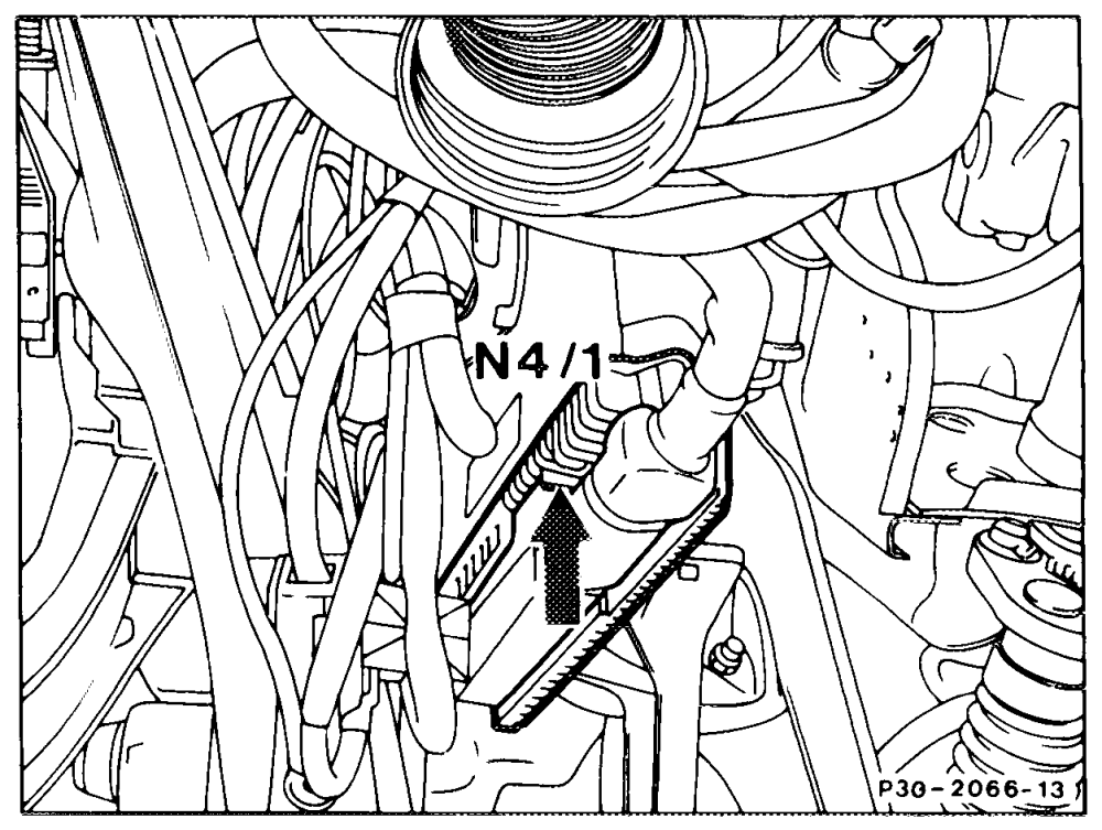
The electronic accelerator control unit is located below the instrument panel, above the pedals. It contains two printed circuit boards with electronic components. The housing is an aluminum alloy with a 35-pin plug connector. The control unit is linked to the wiring harness by a 35-pin connector which is fixed in place by a spring clip (arrow).
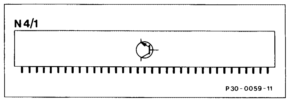
Voltage is supplied to the potentiometer for the electronic accelerator actuator and electronic accelerator reference potentiometer by the electronic accelerator control unit when the ignition starter switch is in “position 2”. In addition, the signals input by the components are processed accordingly. The electronic control unit is split up functionally into the following components:
e Position controller with input amplifier (signal
processing part) Output stage Monitoring device (safety circuit) Cruise control device ASR signal processing
The electronic accelerator control unit is configured in analog technology with the exception of the cruise control computer.
Position controller
As a result, the position of the throttle valve is The input signals to the position controller are fixed. If the driver demands a higher speed by converted, filtered and amplified in the upstream depressing the accelerator pedal, the cruise signal processing parts. Following this, these control device is not active. If the ASR detects signals are appropriately processed in the drive slip during the cruise control mode, the position controller and a defined output signal reduction in engine power (lower speed) has generated for the output stage. priority over the cruise control mode. Once the drive slip has been eliminated, the cruise control
Output stage
resumes the previously stored speed provided The output signal of the position controller is the driver does not demand any other function. passed to the output stage where it is amplified. In addition, this signal determines the positioning
Monitoring device
direction (idle speed direction or full throttle The monitoring device performs safety direction) of the D.C. motor in the electronic functions. The following functions are checked: accelerator actuator. In this case, the D.C. motor is actuated with a frequency of 140-160
e The operating ranges of the electronic
Hz. If the D.C. motor is blocked, a continuous accelerator reference potentiometer and current is output briefly. If the blockage persists, electronic accelerator actuator. the output stage is shut off by the monitoring
e The cables to the electronic accelerator
device. The output stage is short circuit proof to reference potentiometer and electronic accelerator actuator for short circuit or ground. interruption.
Cruise contro! device
e The function of the safety switches in the The cruise control function is integrated in the electronic accelerator reference potentioelectronic accelerator control unit. As with the meter and electronic accelerator actuator. previous electrical cruise control, it is activated and switched off with the cruise control switch. If the cruise control switch is constantly operated <40 km/h and the vehicle accelerated with the accelerator pedal beyond the safety threshold, the cruise control does not switch on. The cruise control cannot be activated if the switch is operated during a brake application. When the cruise control is set, a corresponding input signal is supplied to the position controller.
accelerator actuator, related to the set pedal is released. Depending on the position of position, which is fixed either by the accelerthe accelerator pedal, the contact in the electronic accelerator reference potentiometer ator pedal (reference potentiometer), cruise control or by the ABS/ASR control unit. or in the electronic accelerator actuator is Short circuit of output stage of D.C. motor. closed. To avoid any interruption in the voltage supply occurring when a rapid adjustment
e Battery voltage at electronic accelerator
control unit. Below a battery voltage of 6 V, movement is made to idle speed, a switching transistor is connected additionally to the output the electronic accelerator control unit switches off, and switches on again when of the electronic accelerator control unit. the voltage rises. When the safety switch in the electronic accelerator reference potentiometer opens, this The function of the safety switch is independent transistor assumes the voltage supply to the fuel pump relay for max. 150 ms. In the cruise of the electrical ‘ electronic control function of the driving torque control loop. The current control mode, the safety switch in the electronic through the safety switches of electronic accelerator reference potentiometer is open, as accelerator reference potentiometer and is the safety switch in the electronic accelerator electronic accelerator actuator is looped through actuator. The switching transistor (as already the control unit. Consequently, in the driving indicated) assumes the task of the safety switch mode or at idling speed the fuel pump relay of the electronic accelerator reference potentio- (terminal 15) is energized. The safety switch in meter to ensure that the fuel pump relay is able the electronic accelerator reference potentioto maintain the voltage supply of the fuel pump meter closes when the accelerator is depressed (terminals 30 and 87 jumped by relay contact). before the safety switch in the electronic The safety switches including switching accelerator actuator opens. transistor are likewise covered by the monitoring device.
Pin assignment of electronic accelerator control Nal
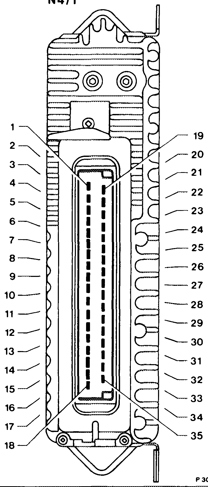
unit
1 Voltage supply, terminal 15 unprotected
2 Voltage supply, terminal 15 unprotected
3 Electronic accelerator actuator (motor)
4 Electronic accelerator actuator (motor)
5 Reference potentiometer, ground
7 Do not create contact!
8 Not assigned
9 Reference potentiometer, voltage supply ( +)
10 Not assigned
11 Battery ground (W10) only on Model 126.036/037/044
12 Electronic speedometer speed signal
13 Safety switch, reference potentiometer
14 Stop light switch
15 Reference potentiometer (wiper signal)
16 Cruise control switch (Decelerate, Set) 17. Not assigned
18 Cruise control switch (Resume)
19 Do not create contact!
20 Electronic accelerator actuator (motor)
21 Electronic accelerator actuator (motor)
22 Battery ground (W10)
23 Battery ground (W10)
24 Not assigned
25 Not assigned
26 Electronic accelerator actuator, potentiometer voltage supply (+)
27 Not assigned
28 Electronic accelerator actuator, potentiometer (wiper nal signal)
29 Electronic accelerator actuator (safety switch)
30 Fuel pump relay, terminal 15, contact 9
31 To ABS/ASR control unit (throttle valve actual value) P30-0017-17
32 Cruise control switch (Accelerate, Set) i
33 Starter lockout and backup light switch, drive stage „R”
34 From ABS/ASR control unit (throttle valve set value)
35 Cruise control switch (Off)
Speed signal
The speed signal from the electronic speedo-
meter is input to the electronic accelerator
control unit for the cruise control function. It is
used by the electronic accelerator control unit
only for the cruise control. If there is no speed
signal, this does not impair acceleration nor the
driving torque control.
When the brake is applied, the cruise control device is supplied with a signal change through the stop light switch. This means that the ground connection is interrupted. The cruise control function is immediately canceled. At the position controller, the input signal of the cruise control device is canceled. As a result, the electronic accelerator actuator is controlled so that the throttle valve is moved back to the set point by the accelerator pedal. The position of the accelerator pedal has priority. If there is no ground signal from the brake switch, the cruise control is switched off. This does not impair acceleration nor the driving torque control.
Selector lever position signal
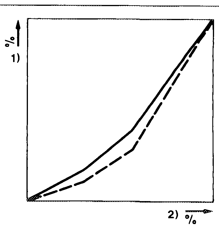
When the driving position “R” is engaged by the selector lever, the position controller is supplied with an input signal from the starter lockout and backup light switch. As a result, a characteristic curve switchover is performed in the position controller. When reversing, the throttle valve is opened less rapidly up to approximately half pedal travel. This achieves enhanced comfort for reversing.
1 Throttle valve angle P30-0061-134 2 Accelerator pedal travel
ABS/ASR control unit signal
An exchange of information occurs (200 times per second) between the ABS/ASR control unit and the electronic accelerator control unit. The electronic accelerator control unit detects from the shape of the signal from the ABS/ASR control unit whether drive slip exists and what maximum throttle valve opening is permissible. Depending on the slip conditions at the driven wheels, the throttle valve can also be fully closed by an appropriate ASR control signal.
This is also possible even if the driver or the cruise control inputs full throttle. The electronic accelerator control unit constantly informs the ABS/ASR control unit by means of a similar feedback signal (throttle valve actual value) of the momentary position of the electronic accelerator actuator and thus of the throttle valve. The ABS/ASR control unit can thus check during an ASR control cycle whether the electronic accelerator follows the control commands of the ASR device. If a fault exists in the electronic accelerator range (without cruise control function) (actuator does not have voltage supply), the feedback signal disappears and the ASR device shifts to fault. The ASR indicator lamp (A1e22) lights up.
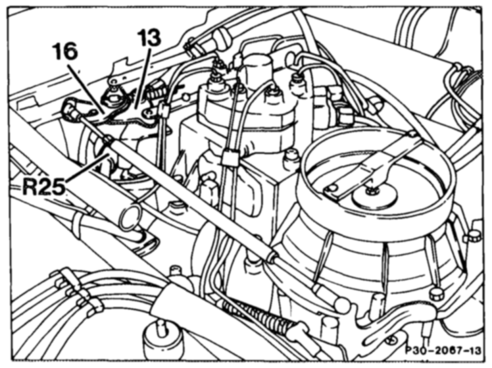
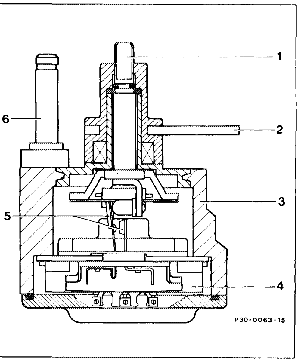
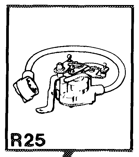
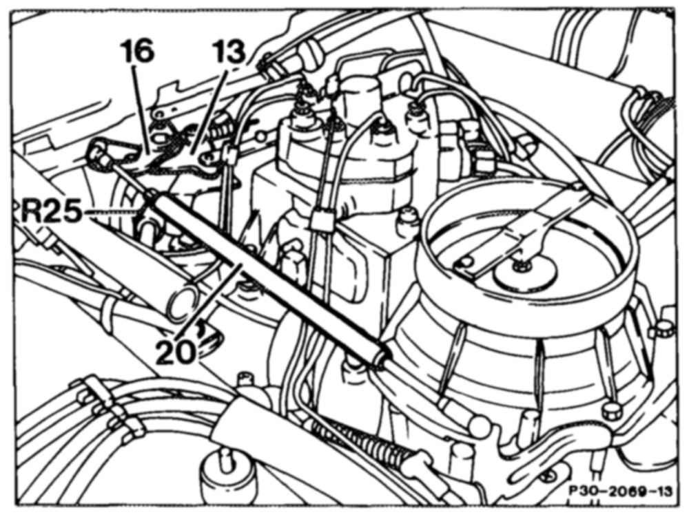
meter is attached to the intake manifold at the level of engine cylinder No. 4. It consists of a variable electrical resistor (potentiometer) and a safety switch. The safety switch is designed as a double-contact switch. Both components are operated by the potentiometer shaft to which the accelerator control lever is attached. The fulcrum lever is mounted on the pin next to the potentiometer shaft. In ignition starter switch “position 2” or when the engine is running, the potentiometer is activated with a constant voltage by the electronic accelerator control unit. The potentiometer position is altered by the adjusting movement at R25 Reference potentiometer the accelerator pedal through the accelerator control linkage, fulcrum and accelerator control 13 Accelerator control lever 16 Fulcrum lever levers. The potentiometer feeds back a defined variable voltage to the electronic accelerator control unit as a function of the accelerator pedal position. This signal is further processed in the position controller of the electronic accelerator control unit. If the accelerator pedal is not depressed (idle position), the safety switch of the electronic accelerator reference potentiometer is open. Voltage is supplied to the input side of the safety switch when the ignition is switched on or when the engine is running. The switch point of the safety switch is 4–6° adjustment angle above the idle stop.
Adjustment shaft anr Wn = Reference potentiometer relay lever Housing Potentiometer Safety switch Pin for fulcrum lever
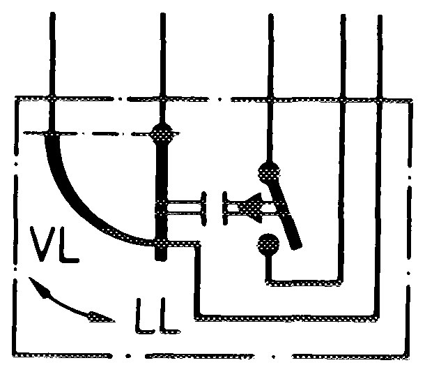
lf the safety switch is closed, terminal 15 at the fuel pump relay is energized. If the accelerator pedal is moved from full throttle toward idle speed, the safety switch opens at approx. 6–4° before idle speed stop. In the idle position, the closed safety switch in the electronic accelerator actuator (M16/1) adopts this voltage supply. The R25 maximum current flow must not exceed 1 A. The switch is not short circuit proof to ground.
1. Electronic accelerator actuator (M16/1)
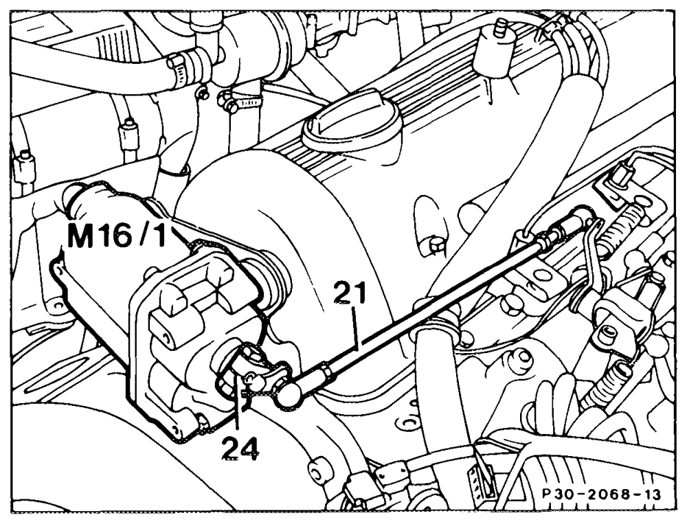
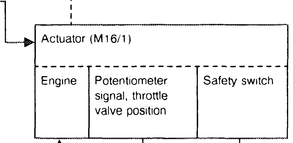
The electronic accelerator actuator is attached to the face end of engine cylinder 1 by a mounting bracket. It consists of a D.C. motor with multistage gear to which the output lever for the accelerator control linkage is attached. In addition, the wiper for the potentiometer and the safety switch are coupled to the output shaft. Here, too, the safety switch is designed as a double-contact switch. When the ignition starter switch is in “position 2″ or when the engine is running, the potentiometer is controlled with a constant voltage from the electronic accelerator control unit. The output signal of the potentiometer to the electronic accelerator control unit acts as a position feedback of the momentary Electronic accelerator actuator M16/1 throttle valve position. This signal is further Connecting rod 21 processed in the position controller of the elecOutput lever 24 tronic accelerator control unit. If deviating signal tones are received, the electronic accelerator control unit alters the position of the throttle valve.
erator actuator is 88–92°. This enables the throttle valve to be moved by the accelerator control linkage from idle speed through to full throttle stop and vice versa.
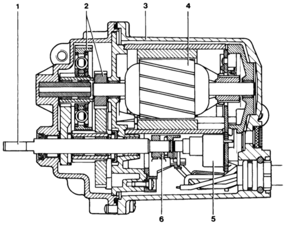
The D.C. motor features a high positioning rate. The total adjustment angle is covered in approx. 120 ms. At the same time, this ensures a high positioning accuracy.
P300066–55
1 Output shaft 4 Armature
2 Reduction gear 5 Potentiometer
3 Housing 6 Safety switch
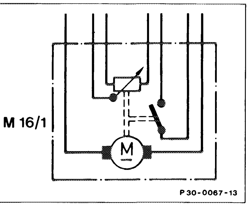
The power consumption at maximum positioning rate is 8 A. If the accelerator pedal is not depressed, the safety switch is closed. It is energized when the ignition starter switch is in “position 2″ or when the engine is running, and at the same time terminal 15 at the fuel pump relay is also energized. When the accelerator pedal is depressed, the safety switch opens. The switching point is approx. 8–12° above the idle position. The safety switch of the electronic speedometer reference potentiometer (R25) now assumes the voltage supply for the fuel pump relay. To avoid any switching lag when the accelerator pedal is moved rapidly, a switching transistor assumes the voltage supply for the fuel pump relay for a defined period (see monitoring device, electronic accelerator control unit). The maximum current flow must not exceed 1 A. The switch is not short circuitproof to ground.
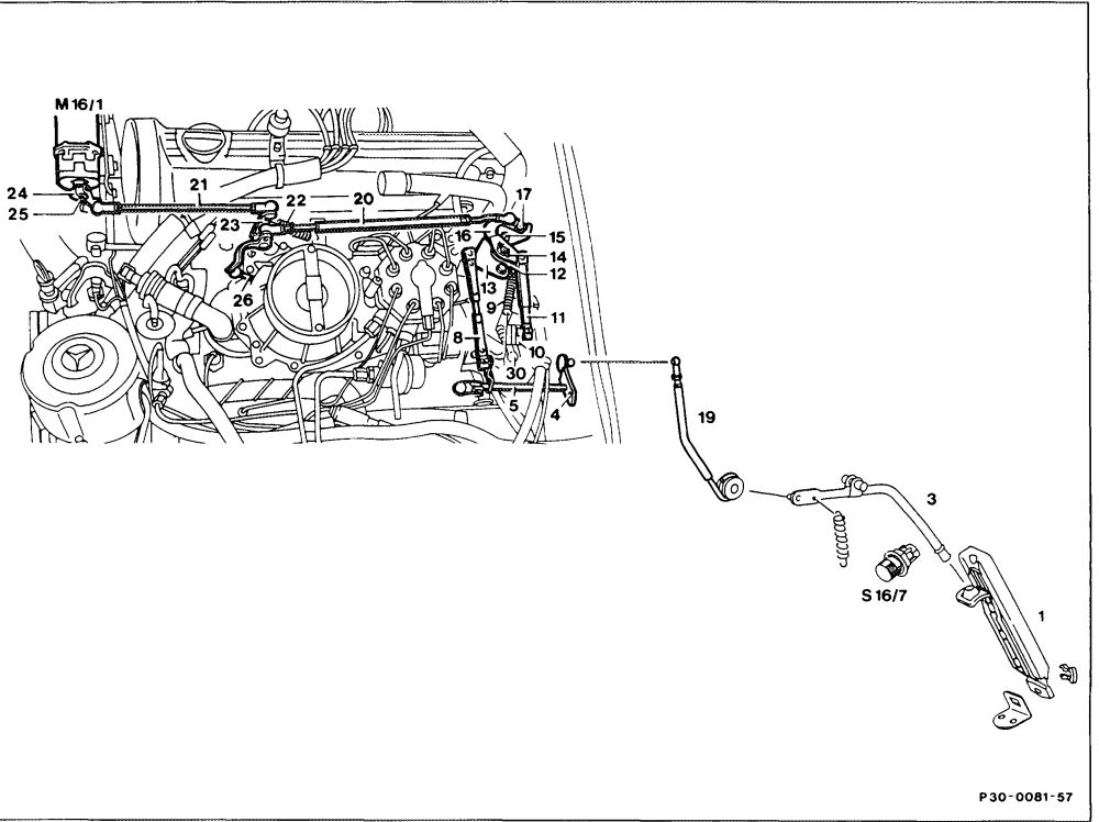
Connecting rod
Mechanical parts
Idle travel rod (redundancy rod)
1 Accelerator pedal Connecting rod
3 Accelerator pedal lever Return spring
4 Longitudinal control shaft adjusting screw Throttle valve relay lever
5 Longitudinal control shaft Output lever
8 Connecting rod Locking element
9 Return spring Connecting rod
10 Relay lever Control pressure cable
1 Connecting rod
12 Reference potentiometer relay lever
Electrical/Electronic parts
13 Fulcrum lever M16/1 Electronic accelerator actuator
14 Locking element $30/2 Kickdown switch
15 Roller
16 Accelerator control lever
17 Roller
The position of the accelerator pedal is input to the electronic accelerator reference potentiometer through the accelerator pedal, accelerator pedal lever, accelerator control linkage, fulcrum and control levers. The throttle valve is then always adjusted by means of the electrical / electronic components – electronic accelerator reference potentiometer, electronic accelerator control unit and actuator.
The throttle valve is operated by the output lever of the electronic accelerator control unit and actuator by means of the accelerator control linkage and relay lever. The adjustment travel ranges from idle speed stop to full throttle stop. If a fault occurs in the electrical / electronic components, the throttle valve can be adjusted by means of the idle travel rod (redundancy rod). This enables the vehicle to be operated at approx. 2/3 engine output.
Block diagram accelerator control
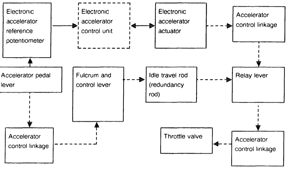
Accelerator pedal _ ee ~
a electric cables nee mechanical connections
Idle travel rod (redundancy rod)
The idle travel rod (20) is a spring-tensioned accelerator control rod. It connects the accelerator control lever at the electronic accelerator reference potentiometer with the relay lever on the throttle valve side. When the throttle vaive is adjusted electrically / electronically, the idle travel rod is also moved. It performs the following tasks:
e If excessive driving torque exists at the
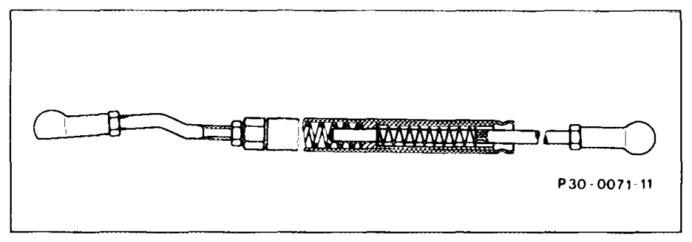
driven wheels, the idle travel rod enables the throttle valve to be moved against the accelerator pedal position. This adjustment movement is assisted by the return springs on the throttle valve relay lever and on the throttle valve. A fixed accelerator control linkage in place of the idle travel rod is impractical as this would not permit an ASR control mode.
e@ In the cruise control mode, the control
pressure cable of the automatic transmission is operated from the electronic accelerator actuator. This enables the transmission to shift down at high engine load.
e If there is any fault or failure in the electrical
/ electronic components, the idle travel rod performs the adjustment of the throttle valve. This ensures that the vehicle can still be driven and permits approx. 2/3 of available engine output to be utilized. The emergency driving facility is activated. The driver can detect this from the higher accelerator pedal forces and by the ASR indicator lamp lighting up.
K. Matching engine — electronic accelerator reference potentiometer —
electronic accelerator actuator — electronic accelerator control unit
Engine Model Electronic accelerator Electronic accelerator Electronic accelerator reference potentiometer actuator control unit Part No. Part No. Part No.
116,117 126 006 548 85 17 003 545 50 32 126 545 00 32 sup to 10/88 126 545 07 32 =—-11/88 – 07/89 126 545 08 32 as of 08/89