Checking, replacing valve guides
WIS 05-285
Valve guides
Stages Color Basic bore in Overlap!) Outer dia. Valve guide inner dia. coding cylinder head 14.030–14.035 0.008–0.020
2 Standard dim. 14.043—14.050 grey-brown © = Repair stage 14.214—14.222 red 14.198—14.203 0.011—0.024 9.000–9.015
8 Standard dim. 15.043-15.050 grey-brown 15.030—15.035 0.008—0.020
5 Repair stage 15.214—15.222 red 15.198—15.203 0.011—0.024
The overlap must be between 0.007 and 0.025 mm.
Special tools
Plug gauge 9 mm dia. for intake and exhaust valve guide – 117 589 03 23 00
Knocking-out mandre! 9 mm dia. intake and exhaust Gres cent Plug gauge for valve guide basic bore oa Reamer 14.035 mm dia. intake Ti004-10587 Reamer 15.035 mm dia. exhaust — 11004-10587 Broach 14.2 mm dia. intake Broach 15.2 mm dia. exhaust – 110 589 00 53 00
Guide sleeve for Engines 116.960/961 and 117 elenld EEE 11004 ~ 10589 broach intake 14.2 mm dia. Eo ines 116.962/963 M0 oD it 1% – 102 589 00 63 00
(> Guide sleeve for broach exhaust 15.2 mm dia. E1004 -10590 – 117 589 00 63 00
Installing mandrel 9 mm dia. intake and exhaust (1st version) – 110 589 00 15 00
Installing mandrel 9 mm dia. intake and exhaust (2nd version) – 110 589 06 15 00
Reamer 8.99 mm dia. H 7 intake and exhaust s00e—e197 – 000 589 10 53 00
Engine Valve Valve guide Guide sleeve Broach basic bore Part No. Page Part No. mm
116.962/963 B Intake 14.2 116.960/961, 102 589 01 63 00 A 117 115 589 00 53 00 – 102 589 00 63 00
117.96 A Exhaust 15.2 116 B 110 589 00 53 00 – 117 589 00 63 00
Note In the event of repairs, cylinder heads with standard normal dimension valve guides must be fitted with standard dimension valve guides (grey-brown). First, ream basic bores with reamers 14.035 mm dia. (intake) and 15.035 mm dia. (exhaust) to avoid too great an overlap.
Basic bores in which the use of standard dimension valve guides do not provide an adequately tight seat (minimum interference 0.007 mm) must be machined with broaches for repair stage valve guide installation.
The broaches must be driven through the basic bores with a plastic hammer and the aid of guide sleeves.
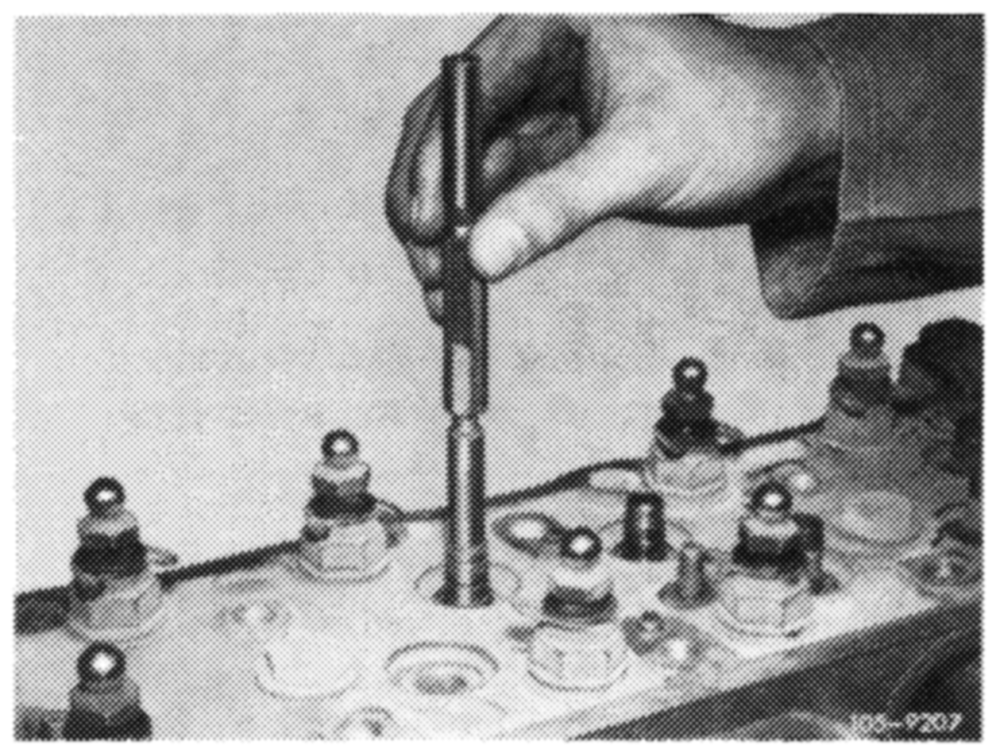
With cylinder head removed, check valve guides by means of plug gauge in longitudinal and transverse direction.
Valve guides which accept the no-go end with the wear limit (+ 220) in its entire height (5 mm) must be renewed.
Valve guides which are worn outside on the valve stem seal seat so that the valve stem seal is no longer seated tightly, should also be replaced.
Replacing valve guides
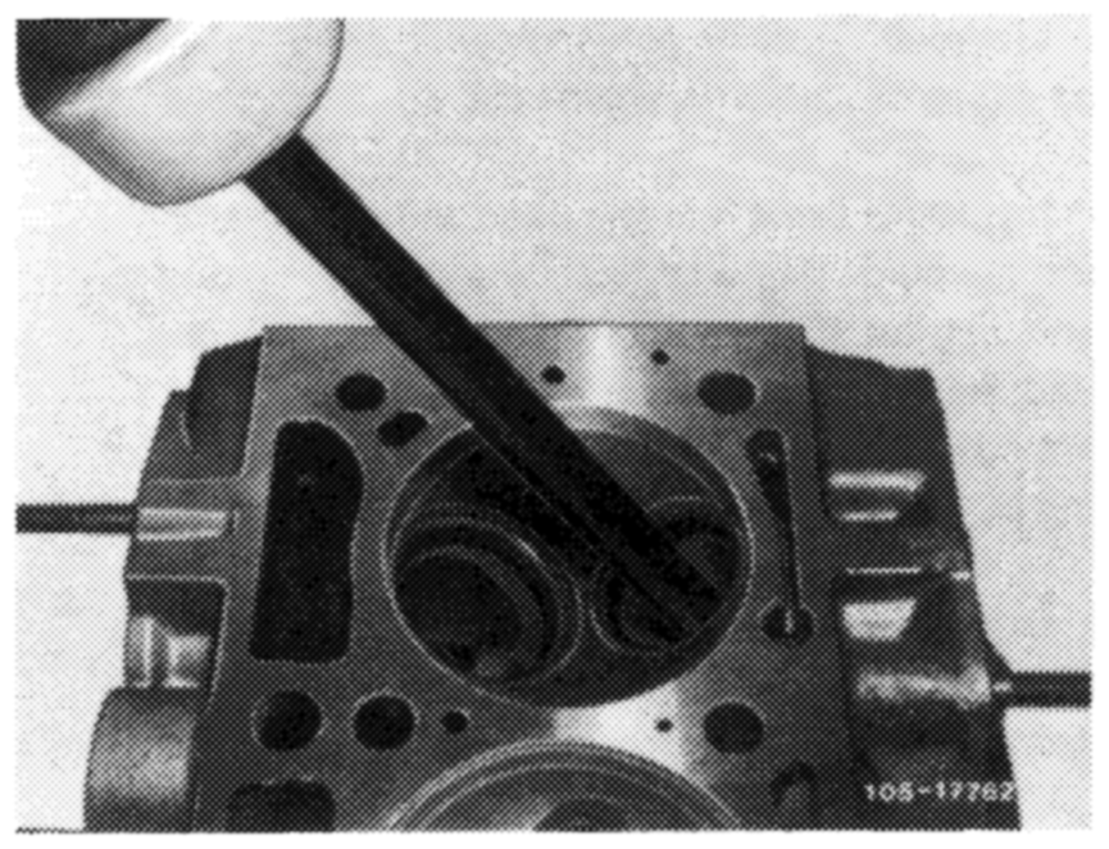
1 Knock out valve guide from combustion chamber end by means of knocking mandrel.
2 Check valve guide basic bore with plug gauge in longitudinal and transverse direction.
Basic bores into which the measuring plug can be inserted at one point for its entire height (8 mm), must be finished to repair stage dimensions.
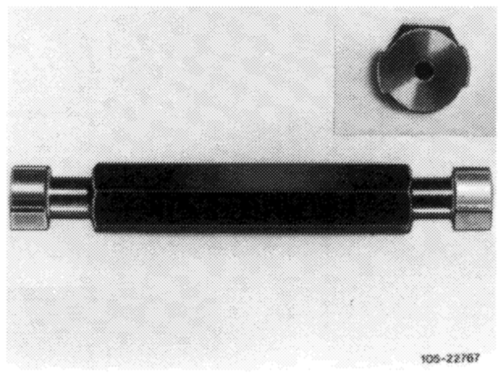
If the measuring plug cannot be inserted fully or only in part, the basic bore for the valve guide can be reamed to normal dimension for the valve guides.
Machining basic bore
Standard dimension
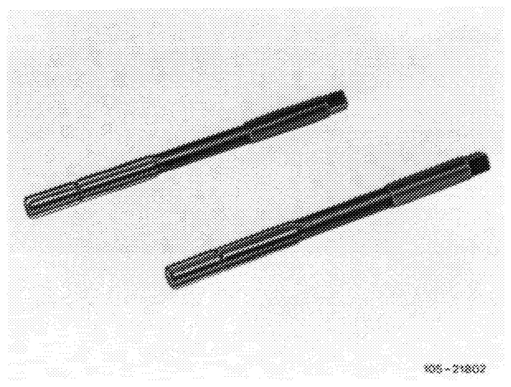
3 Ream basic bore with reamer 14.035 mm dia. or 15.035 mm dia. while lubricating with kerosene. Ream with low pressure and do not cant the reamer.
Note: Handle reamers carefully and put back into protective sleeve so that the cutting edges are not damaged.
Machining basic bore
Repair stage
4 Remove all soot from cylinder head and clean, in particular the inside of the valve seat rings.
5 Remove metal chips (use stiff plastic brush or similar) from the cutting edges of the broach prior to use.
6 Select correct guide sleeve (refer to table). Make sure that the guide sleeve is centered only by the inner diameter of the valve seat ring concerned and is not impaired with carbon residue, casting projections, intake and exhaust port walls etc.
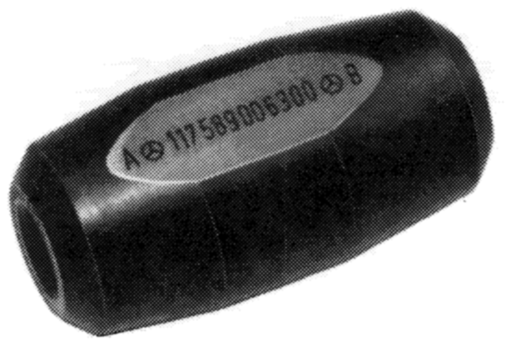
7 Liberally lubricate guide sleeve, basic bore and the entire broach with engine oil.
8 Introduce broach in the direction of broaching into the guide sleeve so that during the subsequent introduction of the guide sleeve into the cylinder head the broach will enter into the bore up to the first cutting edge. Center the sleeve in the valve seat ring by means of rotary movements.
9 Drive broach through the bore by means of an aluminum mandrel approx. 130 mm long and a plastic hammer of approx. 250 g.
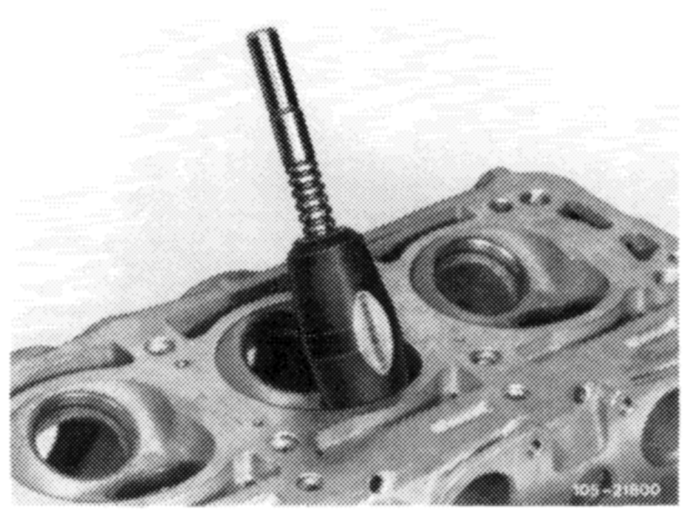
105~- 21801
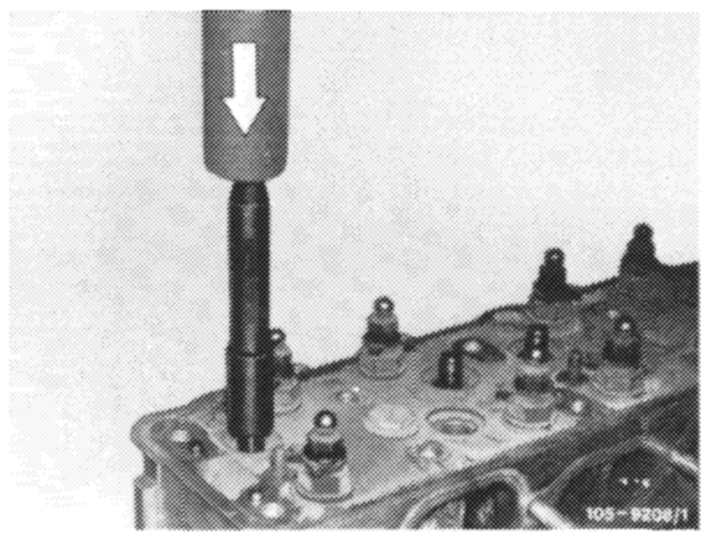
3 minutes) and insert.
If no liquid nitrogen is available, heat cylinder head in a water bath to approx. 80 °C. Drive valve guide into the cylinder head by means of the installing mandrel until the locking ring contacts the cylinder head.
11. Check valve guide for tight seat with the cylinder head in a cooled-down condition.
12 Check inner dia. of valve guide with plug gauge.
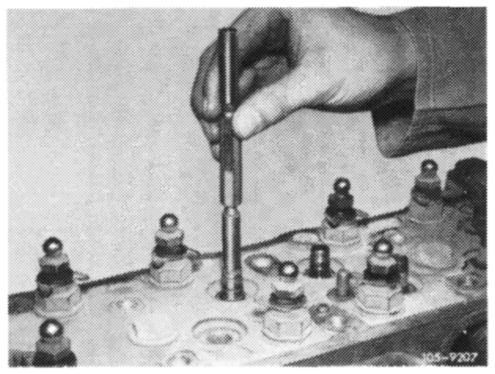
The entire go end should be introduced into the bore.
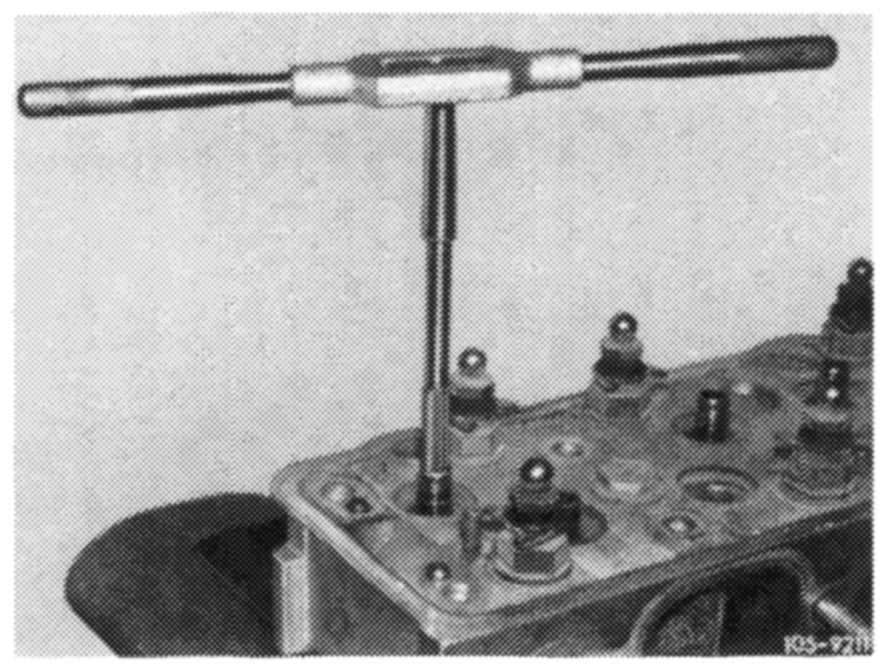
13 If required, ream inner dia. with reamer.
14 Check valve seats for runout and refinish if required.