Testing electronic ignition system with electronic timing adjustment
WIS 15-540
Test requirement
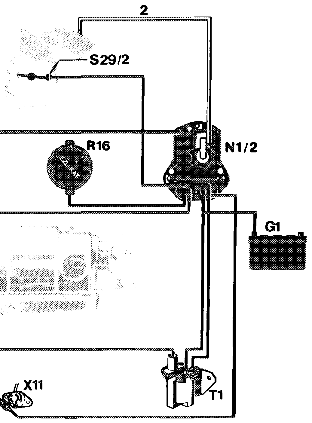
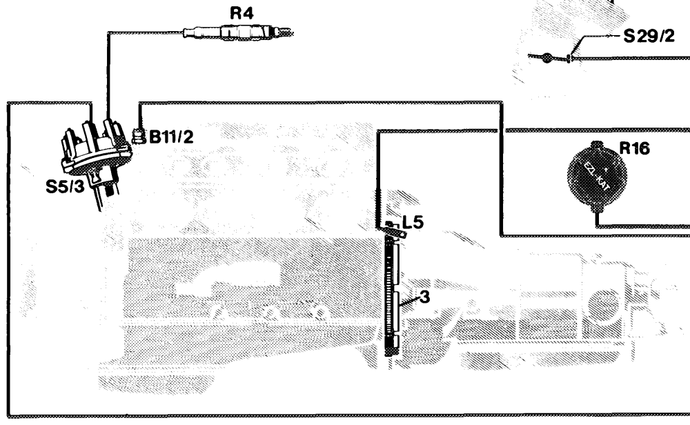
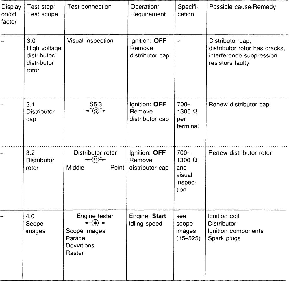
Spark plugs, ignition parts, distributor rotor and distributor cap in proper mechanical and electronic condition. Test e.g. by means of visual inspection, resistance measurement and ignition oscilloscope.
P15-0247–57
Connection diagram for engine tester with oscilloscope B11/2 Coolant temperature sensor (EZL/CIS-E) $29/2 Throttle valve switch, full load/idle G1 Battery T1 Ignition coil LS Crankshaft position sensor X11 Diagnostic socket/terminal block (circuit TD) N1/2 Electronic ignition control unit (EZL) R4 Spark plugs 2 Vacuum line R16 Resistance trimming plug (EZL) – not used 3 Segments on driven plate R16/1 used on USA vehicles $5/3 High-voltage distributor
Pay attention to the safety instructions when working on the ignition system (15-505). Switch off ignition when connecting and disconnecting the plugs at the EZL control unit.
The test is divided into two sections:
A. Engine not running
In this section of the test, the basic functions of the ignition system are tested.
B. Engine running
Fault sources in the ignition advance mechanism or at the appropriate components may influence the performance of the vehicle.
If complaints are received regarding performance, first of all test ignition system. Then, continue troubleshooting the CIS-E injection system.
Special tools
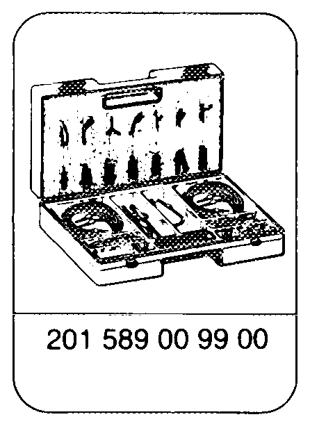
Engine tester e.g. Hermann Datascope 9800 Bosch MOT 301/400 Sun 2110 BEAR D ACE
| Test data Resistances (test values from 0-100° C) | |||
| Ignition coil | _ primary (terminals 1 and 15) | ce Q | co 0.2–0.4 |
| Ignition coil | secondary (terminals 1 and 4) | kQ | 8–13 |
| Position sensor | resistor coils (terminals 7 and 31d) insulation (terminals 7 and ground) | Q kQ | 680-1200 2 200 |
| Distributor cap per terminal, distributor rotor, spark plug connector | 700-1300 | ||
| Voltages (engine not running, ignition switched on) | a a | ||
| Terminals 15 and 31 (contacts 5 and 2 diagnostics socket) V_ | battery voltage | ||
| Between terminals 15 and 1 (contacts 5 and 4 of diagnostics socket) | V | 0 | |
| 4-pin round connector terminals 15 and 31 | Vv | battery voltage | |
| 4-pin round connector terminals 16 and 31 | Vv | battery voltage | |
| Dwell angle | OS | ||
| a At starting speed | 1°-18° or 1–40 % | ||
| At 3500 rpm | |27°-40° or 60–90 % | ||
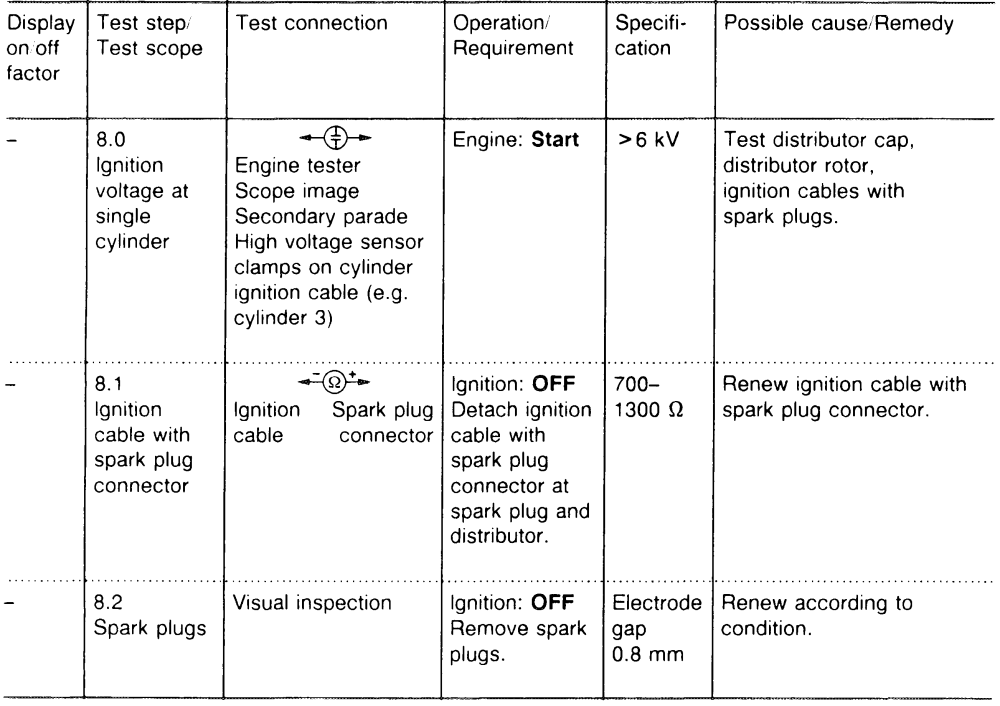
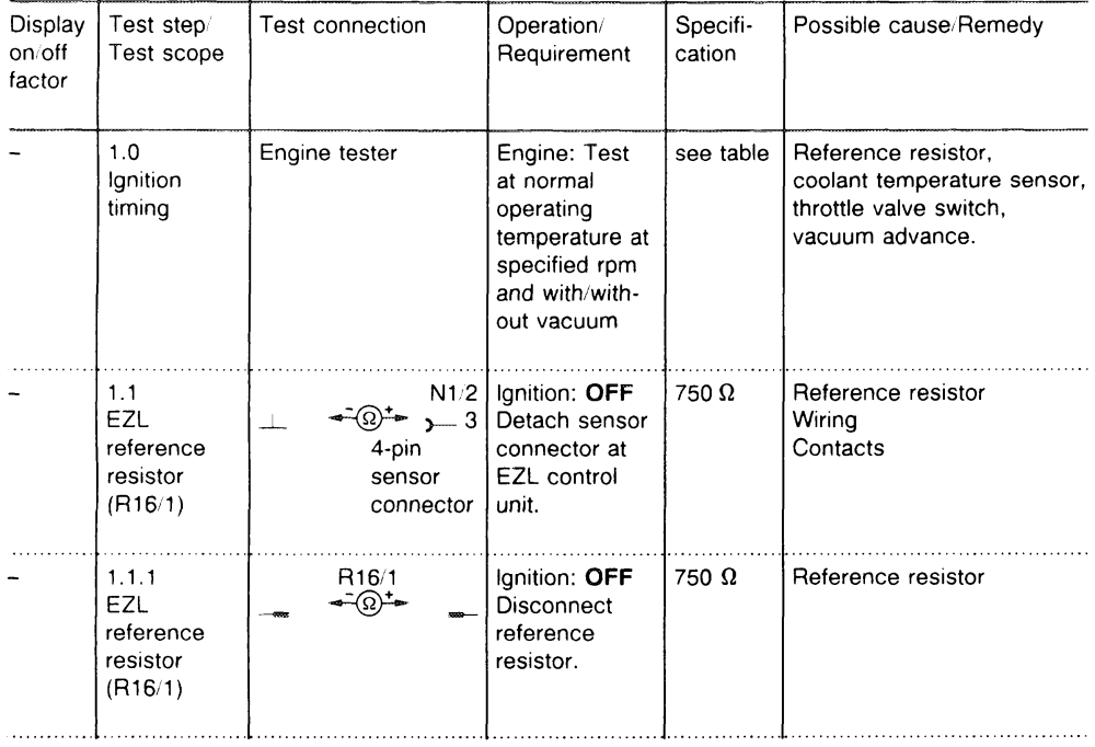
Ignition timing
Engine EZL control unit ‘Resistance Engine speed in Ignition point in ° CA before’ trimming plug rpm TDC or trimming without with plug position vacuum vacuum
effective 1986
116.965 003 545 92 32 Reference 3500 28–32 41–45 003 545 91 32 ist va 760 idle speed 3–7 10–14
117.967 004 545 53 32 Reference 3500 24–28 40–44 968 004 545 55 3 OO. idle speed 3–7 10–14 117. 4 54 2 i rs
in ° CA before TDC 3-7_
Ignition timing at starting speed
15.0713 – 5404
A. Engine not running
Note Symbols for variables measured with
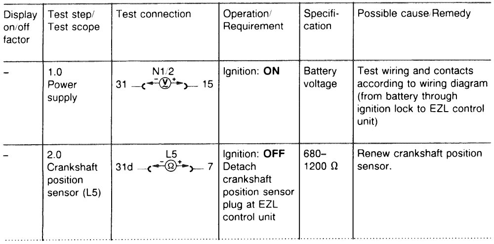
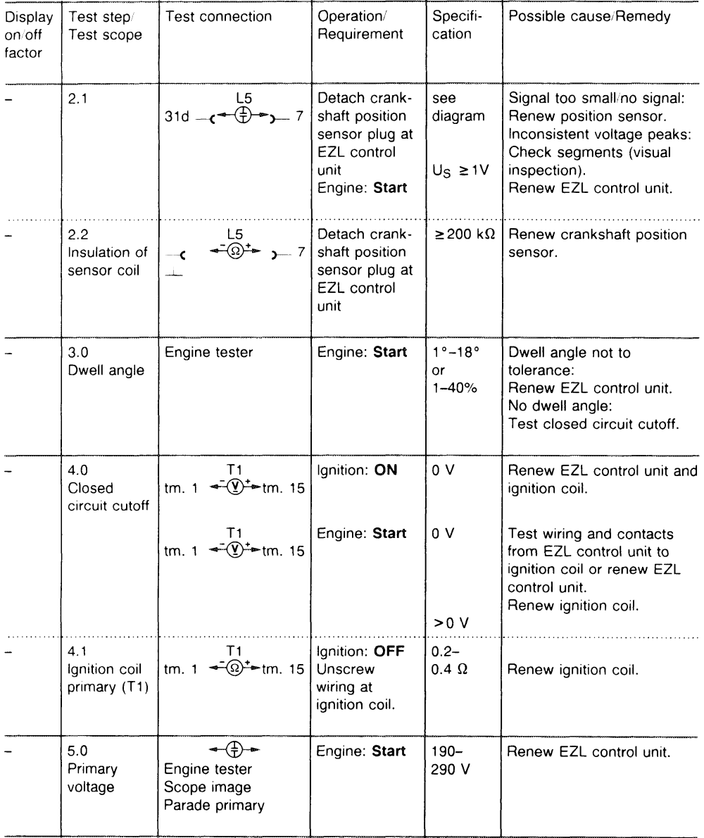
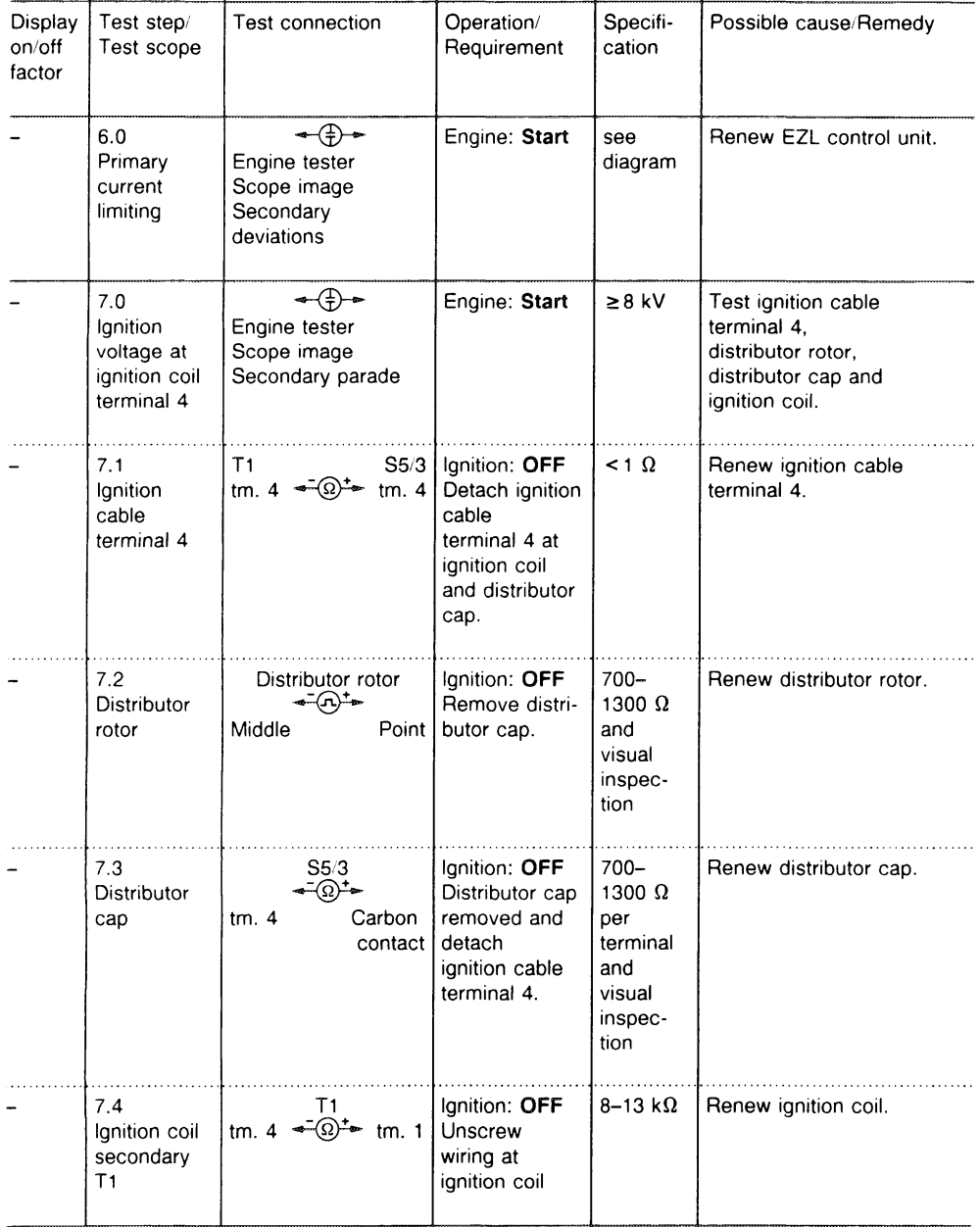
If the specified value of a test step, e.g. step 1, multimeter is in order, continue immediately with step 2. =<W)te Multimeter D.C. voltage mode –@*= Multimeter resistance mode If the specified value of step 1 is not in order, =P Oscilloscope the procedure must be continued with step 1.1.
15.0713 – 5408
B. Engine running
Pay attention to safety instructions (15-505).
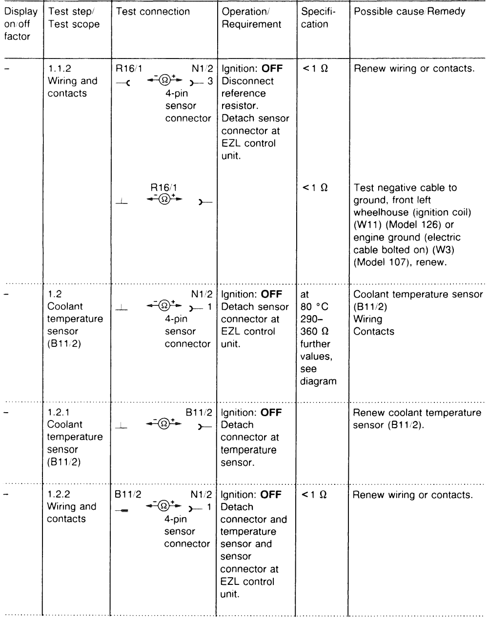
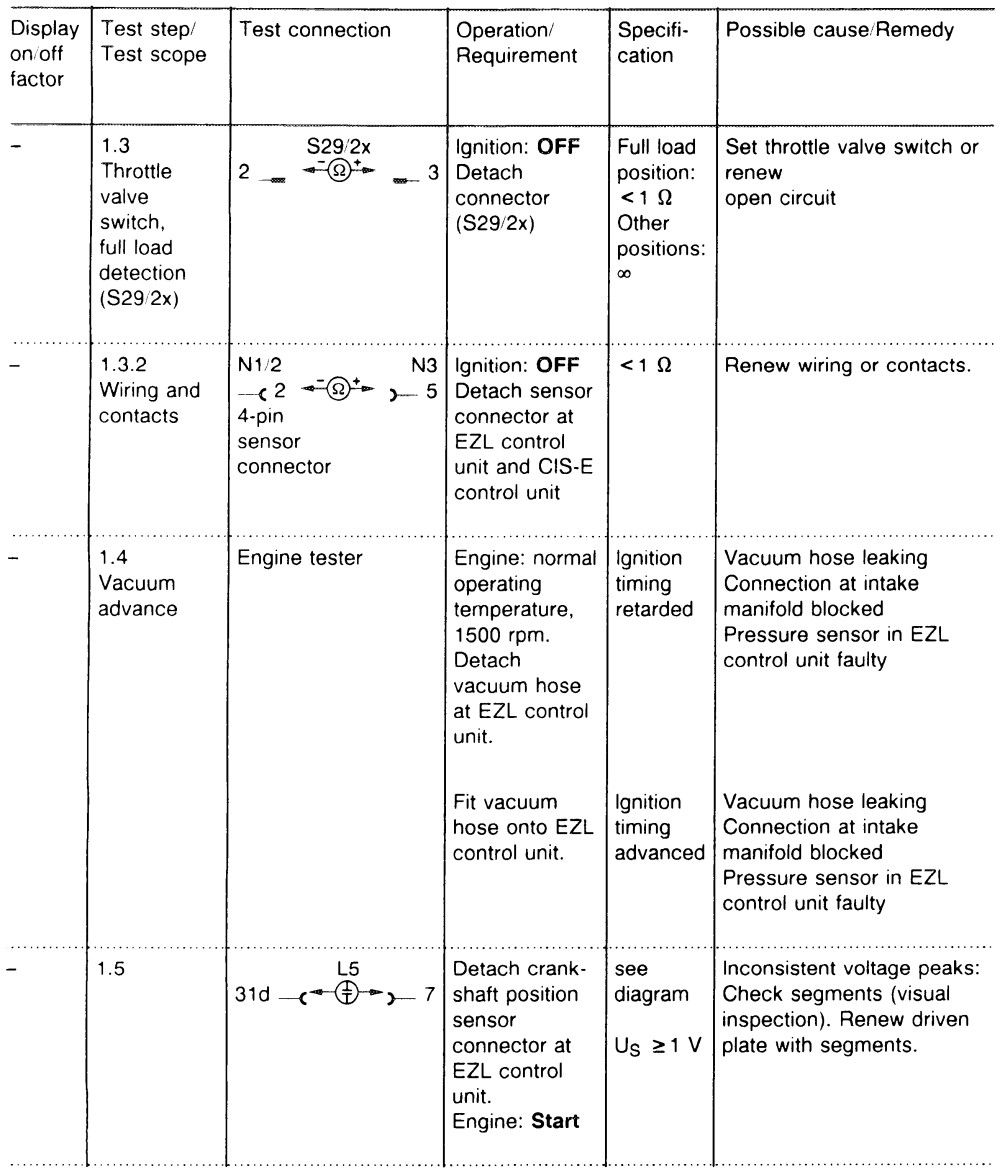
Engine tester Speed – 2.0 Dwell angle 3500 rpm. or Engine at 60–90% normal operating temperature. Detach sensor connector at EZL control unit and vacuum line. Engine: Start
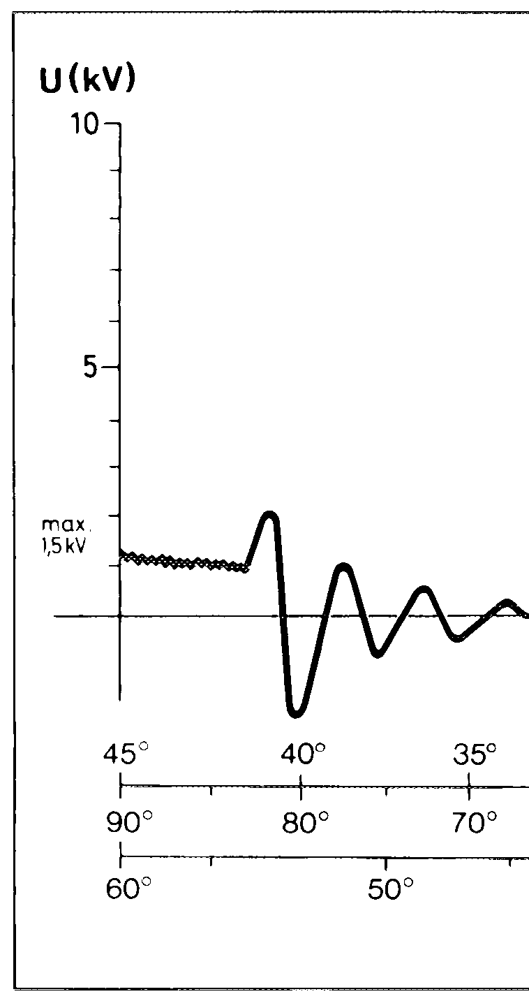
Crankshaft position
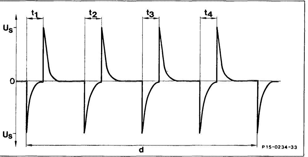
sensor signal (L5)
t1 1st segment t2 2nd segment t3 3rd segment t4 4th segment d Period for one crankshaft revolution
–
= SchlieB + = 7
J Strombegrenzung ——
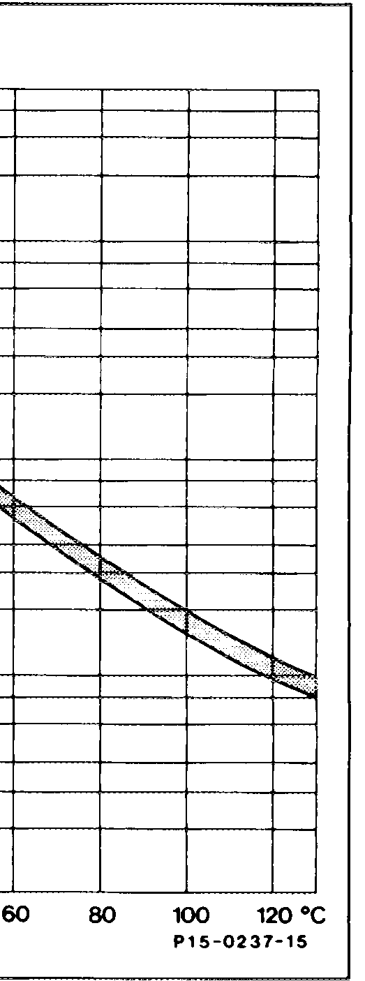
30° 25° 20° 15° 10° 5° 8 Zyl. i 1 ! ! 1 poo EE root 60° 50° 40° 30° 20° 10° 4 Zyl. ’ 40° 30° 20° 10° ’ 6 Zyl P15-0244–55
Current limiting
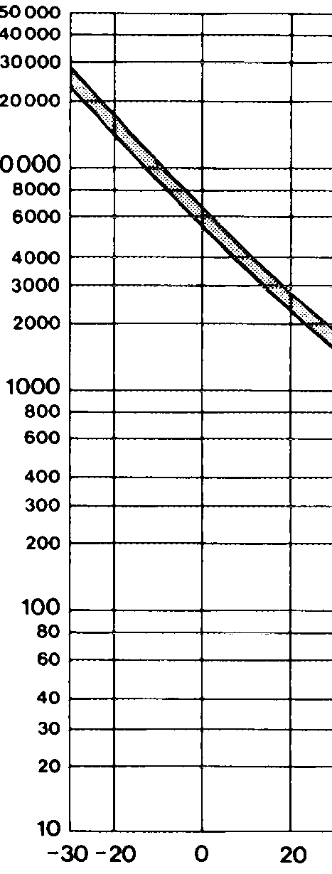
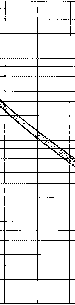
R(Q)
40
Diagram of 4-pole coolant temperature sensor (EZL/CIS-E), (B11/2)
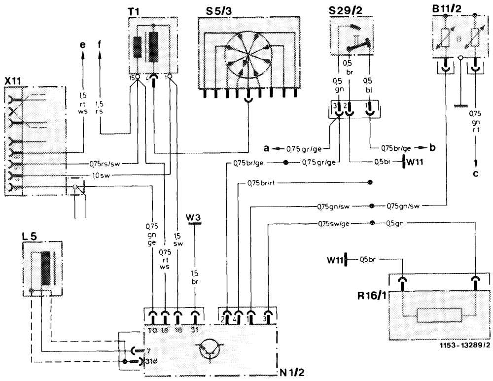
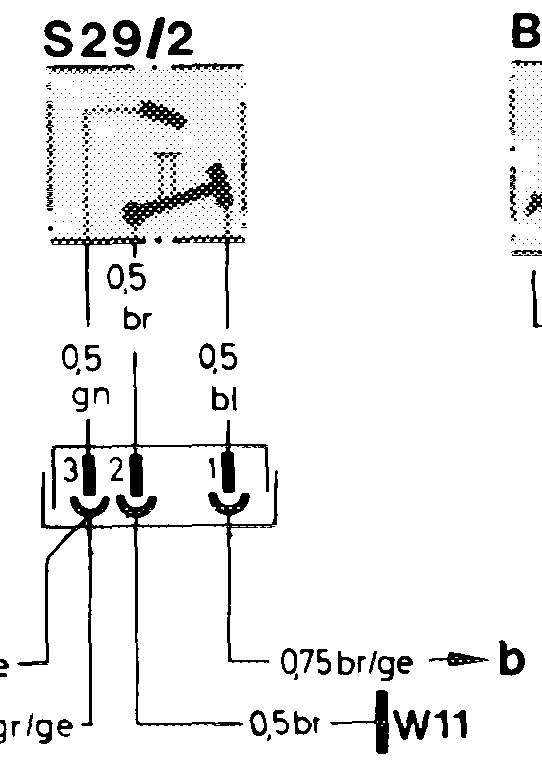
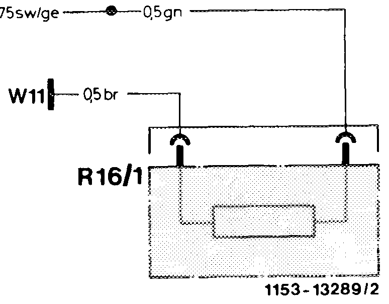
Wiring diagram EZL
Coolant temperature sensor (EZL/CIS-E) B11/2 X11 Diagnostic socket/terminal block (circuit TD) Crankshaft position sensor L5 Connector, transmission overload protection (2X22/1 Electronic ignition contro! unit (EZL) N1/2 pole) Reference resistor (EZL) Connector, interior/engine R16/1 X26 $5/3 High-voltage distributor S2g/2 Throttle valve switch, full load/idle To CIS-E injection system control unit, contact 5 oo om T1 Ignition coil To idle speed control unit, contact 4 Ground, left front wheel housing (at ignition coil) To CIS-E injection system control unit, cont. 21 W3 Ground, at left headlamp unit To plug connection X 26 on engine, socket 3 wa Ground, engine (connection point for ground W111 (circuit 30) To plug connection X 26 on engine, socket 1 wires) (circuit 15) Not used – ends in wiring harness