Checking, regulating engine
WIS 07.3-110
| A. Standard version Testing and adjusting data | |
| Idle speed | 700–750/min |
| Idle speed emission value | 0.5–1.5 % CO |
Battery voltages
12.2 volts Rest potential
10 volts Starting voltage min.
Voltages at ignition coil (with engine stopped and ignition switched on)
Transistorized ignition system TSZ 4
approx. 4.5 volts Voltage on terminal 15
0.5–2.0 volts Voltage on terminal 1
10 volts Series resistor bypass (when starting)
Special tools
Screwdriver 3 mm with tommy handle for adjusting idle speed emission value – 000 589 14 11 00
Oil telethermometer – 116 589 27 21 00
N g i
Conventional tools
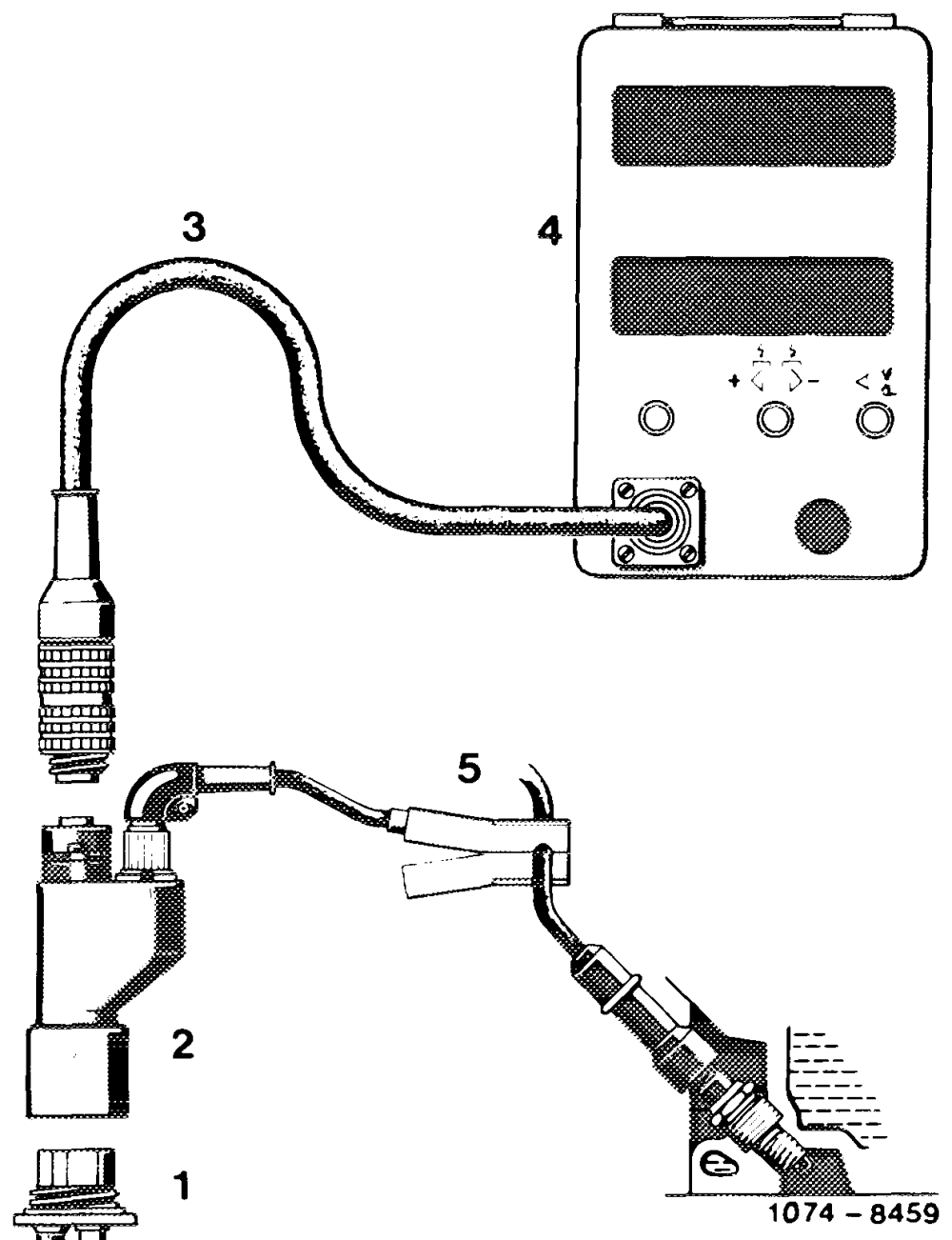
CO-measuring instrument, revolution counter (speedometer), stroboscope, oscilloscope
Digita! tester e.g. Bosch, MOT 001.03
Note Do not regulate when engine is too hot, e. g. immediately following a fast ride or after measuring output on output dynamometer.
Reguiation
1 Switch off air-conditioner or automatic climate control. Move selector lever into position “’P’’.
2 Remove air cleaner.
3 Check engine regulating linkage for easy operation and wear. Lubricate all bearing points and ball sockets.
4 Perform full throttle checkup from inside vehicle (30-300).
-5 Connect test instruments: CO-measuring instrument, revolution counter (speedometer), stroboscope, oscilloscope, digital tester.
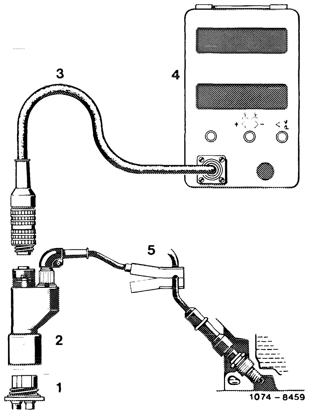
6 Evaluate oscilloscope display.
7 Check.firing point and adjust, if required. Check centrifugal and vacuum ignition adjustment (15-500).
8 Check battery voltages.
Note: Voltmeter connection remains unchanged during tests a) and b).
a) Rest potential — –
Connect voltmeter to battery while paying attention – to polarity and read voltage. Nominal value 12.2 volts.
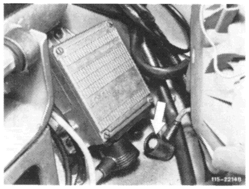
b) Starting voltage
Pull plug for transmitter of ignition distributor from switching unit (green cable) or plug protective plug, part No. 102 589 02 21 00 on diagnosis socket.
Actuate starter for a short moment while reading voltage. Nominal value min. 10 volts. If nominal value is not attained, check battery, charge or renew, if required.
9 Voltages on ignition coil.
Transistorized ignition system TSZ 4
Check voltage on terminal 15 of ignition coil. For this purpose, disconnect positive cable of voltmeter from battery and connect to terminal 15 of ignition coil.
Switch on ignition and read voltage. Nominal value approx. 4.5 volts.
Disconnect positive cable of voltmeter from terminal 15 and connect to terminal 1 of ignition coil.
Switch on ignition and read voltage. Nominal value 0.5–2.0 volts.
Check series resistor bypass by starting engine while reading voltage during start. Nominal value 10 volts.
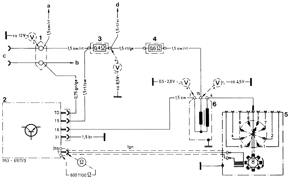
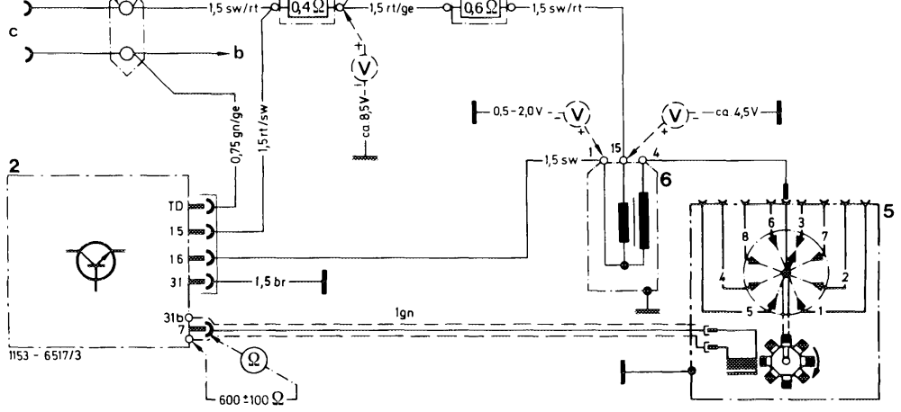
Wiring diagram breakerless transistorized ignition with test values TSZ 4
1 Two-point cable connector a_ Ignition starting switch Color code
2 Switching unit b Instrument cluster, revolution counter br = brown
3 Series resistor 0.4 ohm c Diagnosis socket ge = yellow
4 Series resistor 0.6 ohm d Terminal 16 starter gn = green
5 Ignition distributor with transmitter top rt = red
6 Ignition coil sw = black
10 Check intake system for leaks. For this purpose, spray all sealing points with Iso-Oktan DIN 51756 or benzine.
Attention! Do not use conventional fuel for spraying (unhealthy vapors). Pay attention to fire hazard and do not spray on red-hot parts or parts of ignition system.
11 Run engine to 75—85 °C oil temperature.
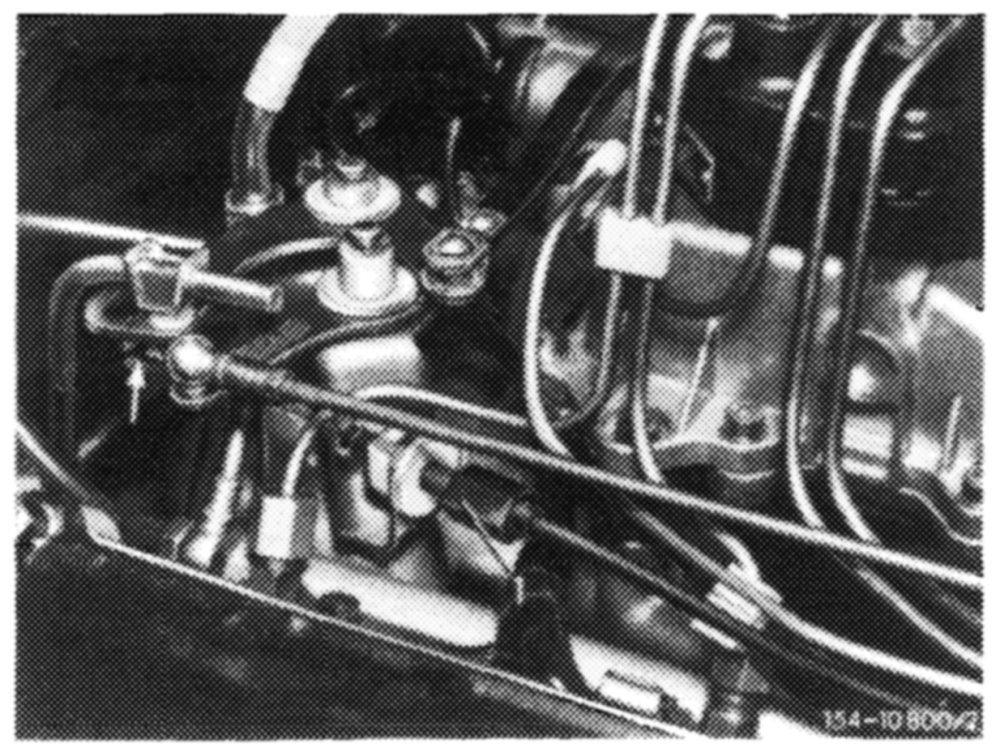
control rests free of tension against regulating lever (arrow). Adjust by means of adjusting nut (1), if required.
13 Check whether throttle valve rests against idle speed adjusting screw. For this purpose, disconnect connecting rod.
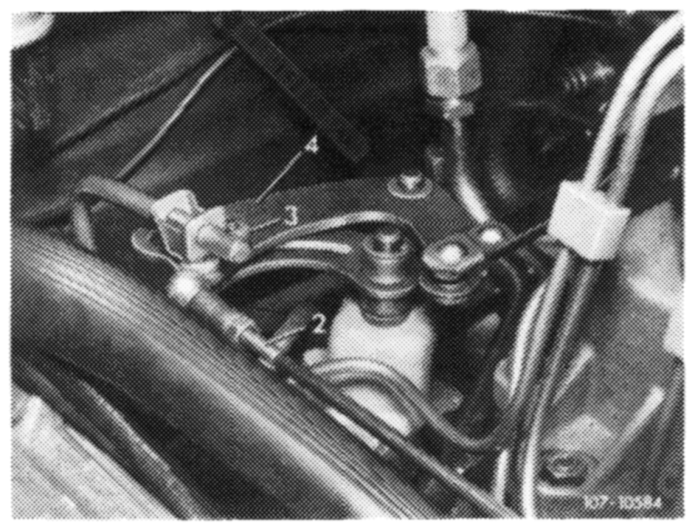
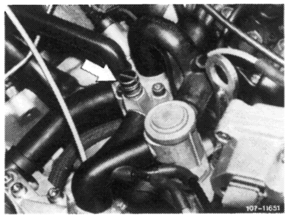
14 Check whether roller (3) in gate lever (4) rests free of tension against end stop. Adjust by means of connecting rod (2), if required.
15 Set to specified speed by means of idle speed air screw (arrow).
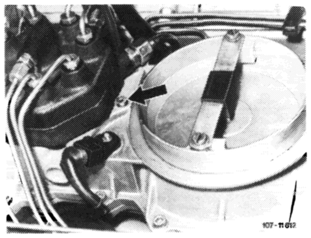
16 Adjust idle speed emission value. For this purpose, unscrew closing plug (arrow).
Attention! On vehicles manufactured after October 1, 1976 remove safety plug first.
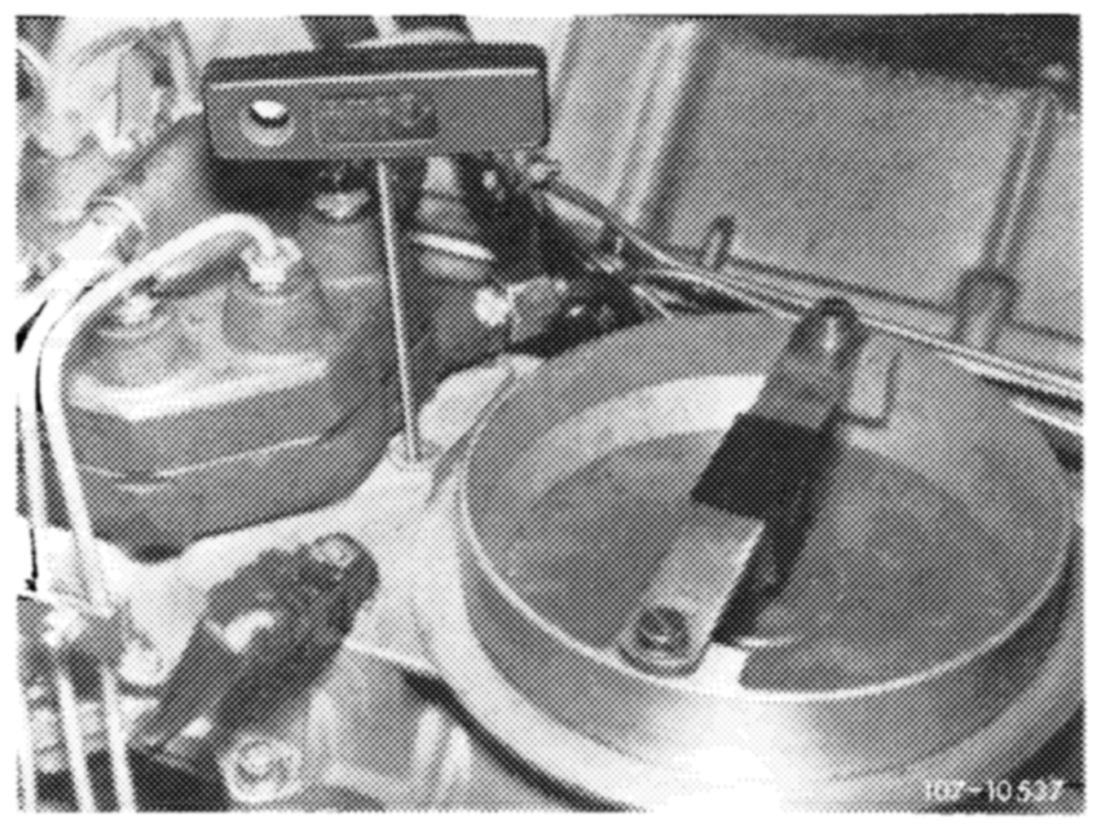
Insert screwdriver through bore into socket of idle speed mixture regulating screw and adjust emission value by turning screw.
Turning counterclockwise = leaner Turning clockwise richer
Close bore for closing plug. Accelerate for a short moment, check idle speed emission value and adjust, if required.
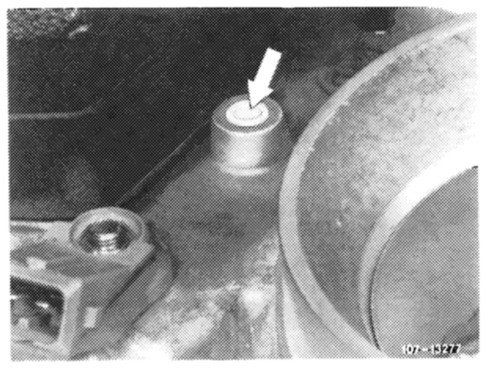
Put back closing plug.
Following adjustment, on vehicles manufactured after October 1, 1976, install a blue safety plug (arrow) MB-part No. 000 997 59 86.
17 Mount air filter. Check idle speed and idle speed emission value once again and adjust, if required.
18 Place selector lever into driving position, switch On air-conditioner, turn power steering to full lock with engine running smoothly. Readjust speed, if required.
B. National version @9)CCs) GSD
Identification: Information plate in respective language on cross member in front of radiator. Adjust engines according to data of respective emission control information plate.
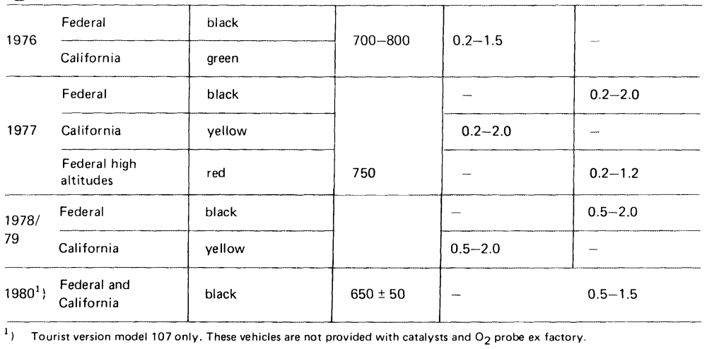
Testing and adjusting data engine 117
| year | Information plate | Idie speed 1/min | Idle speed emission value % CO without air injection | with air injection | |
| silver | 750 | 0.2–2.0 1.0–2.5 | – _ | ||
| _ | Bn | ||||
| in Japanese language | 700-800 | 0.2–1.5 | |||
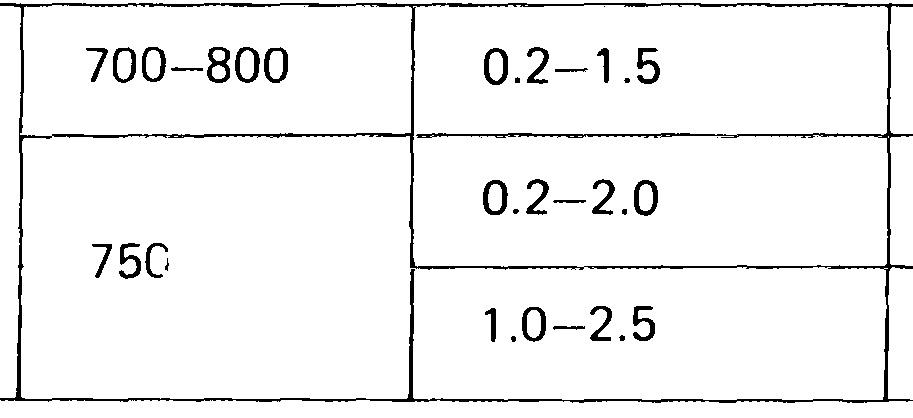
1976
1977/80 blue _
1979/80
So
Special tools
Screwdriver 3 mm with tommy handle for adjusting . a 1004-7807 idle speed emission value – 000 589 14 11 00
Oil telethermometer – 116 589 27 21 00
Conventional tools
CO-measuring instrument, revolution counter (speedometer), stroboscope, oscilloscope
Digital tester e.g. Bosch, Mot 001.03
Note Do not regulate when engine is too hot, e. g. immediately following a fast ride or after measuring output on output dynamometer.
Adjustment
1 Switch off air-conditioner or automatic climate control. Move selector lever into position “P”’.
2 Remove air cleaner.
3 Check engine regulating linkage for easy operation and wear. Grease all bearing points and ball! sockets.
4 Perform full throttle checkup from inside vehicle (30-300).
5 Connect testers: CO measuring instrument, revolution counter, stroboscope, oscilloscope, digital tester, oil telethermometer.
6 Evaluate oscilloscope display.
7 Check firing point and adjust ignition timing, if required. Check centrifugal and vacuum ignition adjustment (15—500).
8 Check battery voltages.
Note: The voltmeter connection remains unchanged during tests a) and b). wou
a) Rest potential
Connect voltmeter to battery while paying attention to polarity and read voltage. Nominal value 12.2 volts.
b) Starting voltages
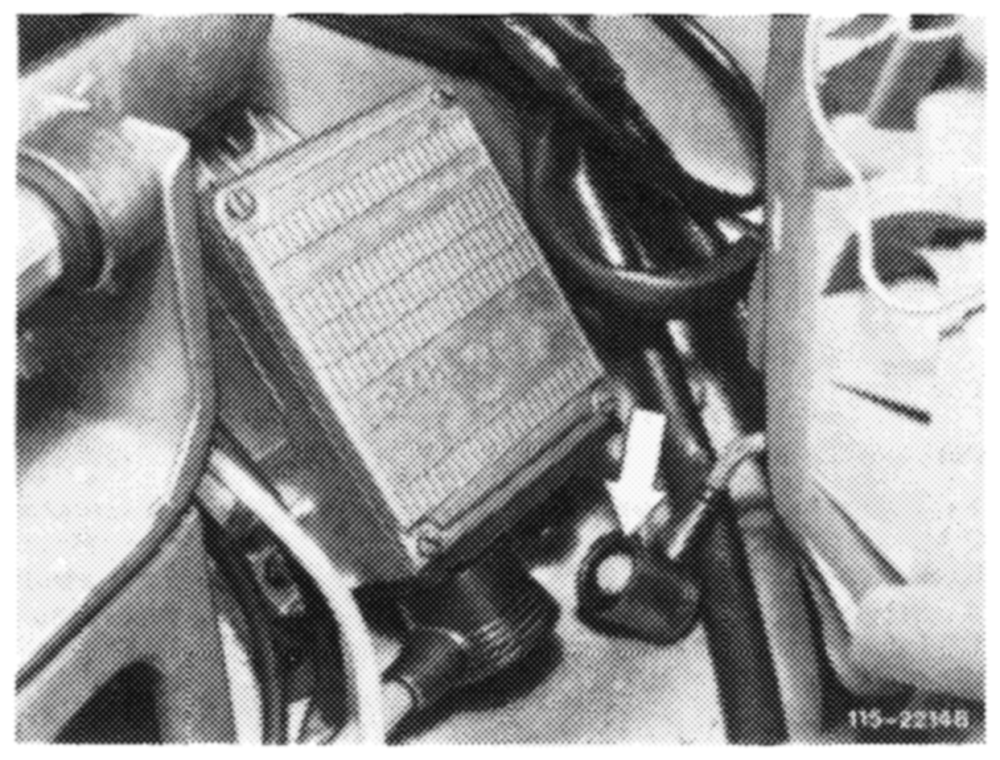
Pull plug of transmitter for ignition distributor on switching unit (green cable) or plug protective plug, part No. 102 589 02 21 00 on diagnosis socket.
Actuate starter for a short moment while reading voltage. Nominal value min. 10 volts. If nominal value is not attained, test battery, change or renew, if required.
9 Voltages on ignition coil.
Transistorized ignition system TSZ 4
Voltage test on terminal 15 of ignition coil. For this purpose, disconnect positive cable of voltmeter from battery and connect to terminal 15 of ignition.
Switch on ignition and read voltage. Nominal value approx. 4.5 volts.
Disconnect positive cable of voltmeter from terminal 15 and connect terminal 1 of ignition coil.
Switch on ignition and read voltage. Nominal value 0.5–2.0 volts.
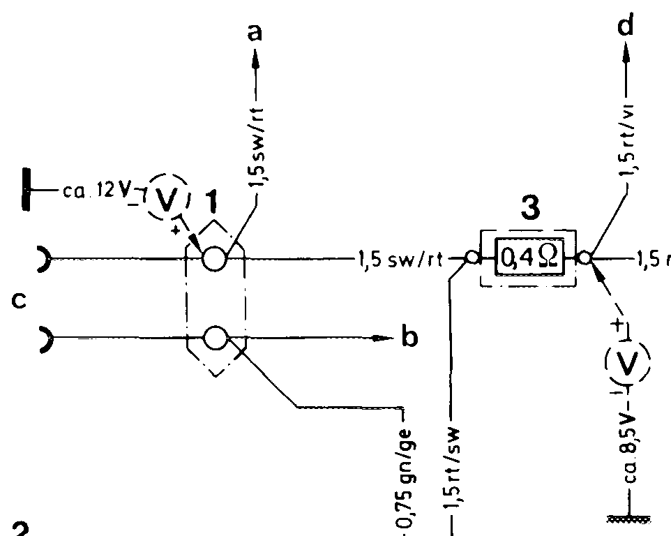
Check series resistor bypass, for this purpose start engine while simultaneously reading voltage while starting. Nominal value 10 volts.
4 =
Wiring diagram breakerless transistorized ignition with test values TSZ 4
1 Two-point cable connector a_ Ignition starting switch Color code
2 Switching unit b Instrument cluster, revolution counter br = brown
3 Series resistor 0.4 ohm c Diagnosis socket ge = yellow
4 Series resistor 0.6 ohm d Terminal 16 starter gn = green
5 Ignition distributor and transmitter top rt = red
6 I[gnition coil sw = black spray all sealing points with lso-Oktan DIN 51 756 or benzine.
Attention! Do not use conventional fuel for spraying (unhealthy vapors). Pay attention to inflammability and do not spray on red hot components or parts of ignition system.
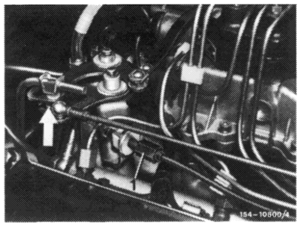
11 Run engine to 75—85 °C oil temperature.
12 Check whether bowden wire for tempomat/cruise control rests free of tension against regulating lever (arrow). Adjust with adjusting nut (1), if required.
13 Check, whether throttle valve rests against idle speed stop. For this purpose, disconnect connecting rod.
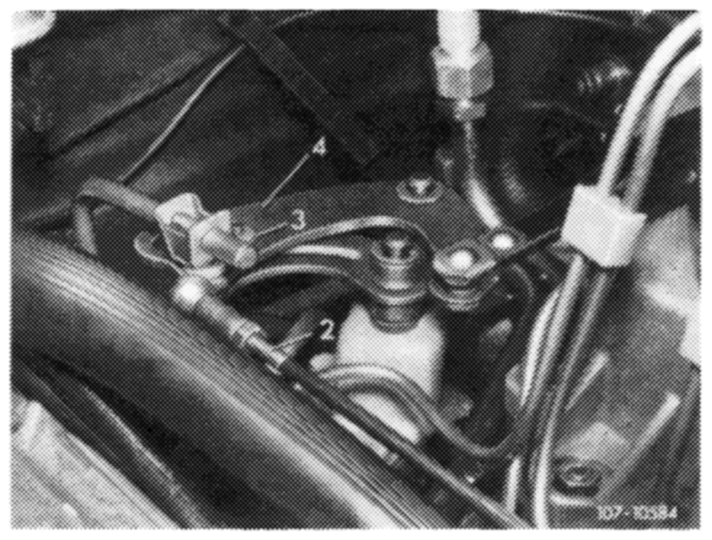
14 Check, whether roller (3) in gate lever (4) rests free of tension against end stop. Adjust with connecting rod (2), if required.
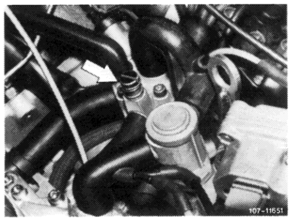
15 Set to specified speed with idle speed air screw (arrow).
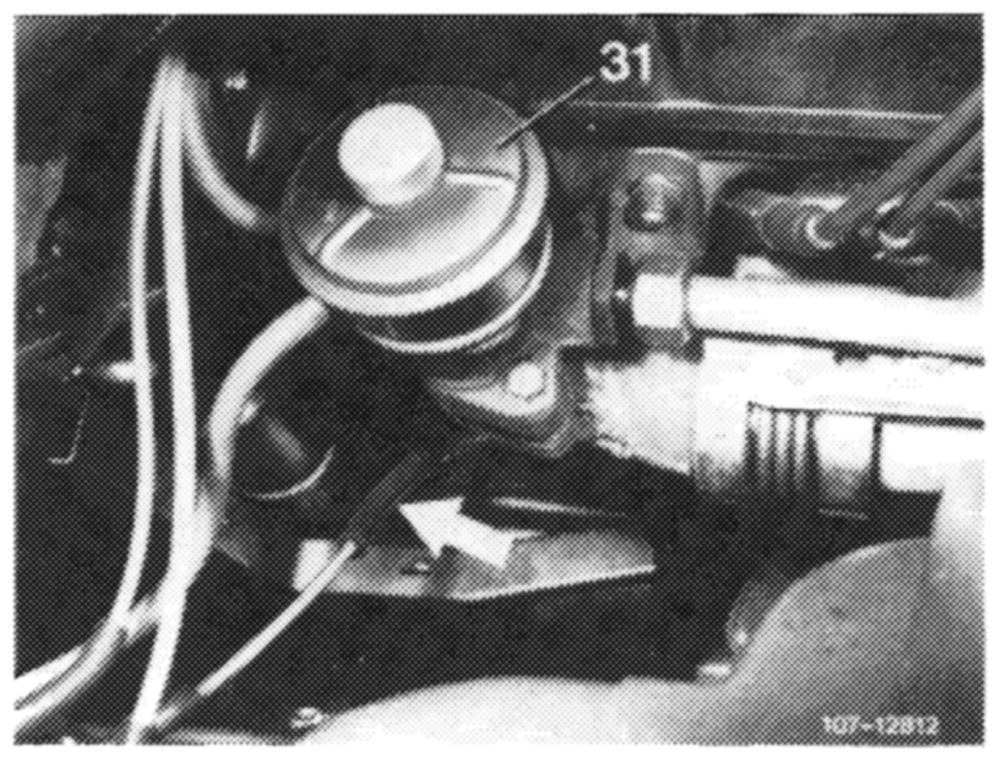
For this purpose, forG) GS starting 1977, pull off connecting hose (arrow) of measuring point (exhaust backpressure line).
Connect CO-measuring instrument and exhaust backpressure line with a hose.
USA tourist vehicles are not provided with a catalyst, for this reason, the emission value can be measured at exhaust end pipe.
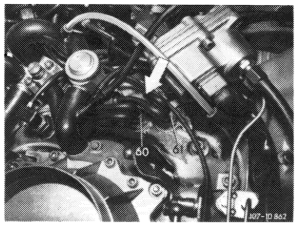
17 Check idle speed emission value.
@ 1977, CG starting 1976, CSD 1976/77, @sa starting 1976
Check idle speed emission value without air injection. For this purpose, pull blue/violet vacuum line (arrow) from blue thermovalve (61) and close connection on thermovalve. This will disconnect air injection.
On @s4) Federal and Federal higher altitudes, check idle speed emission value with air injection (selfaspirating).
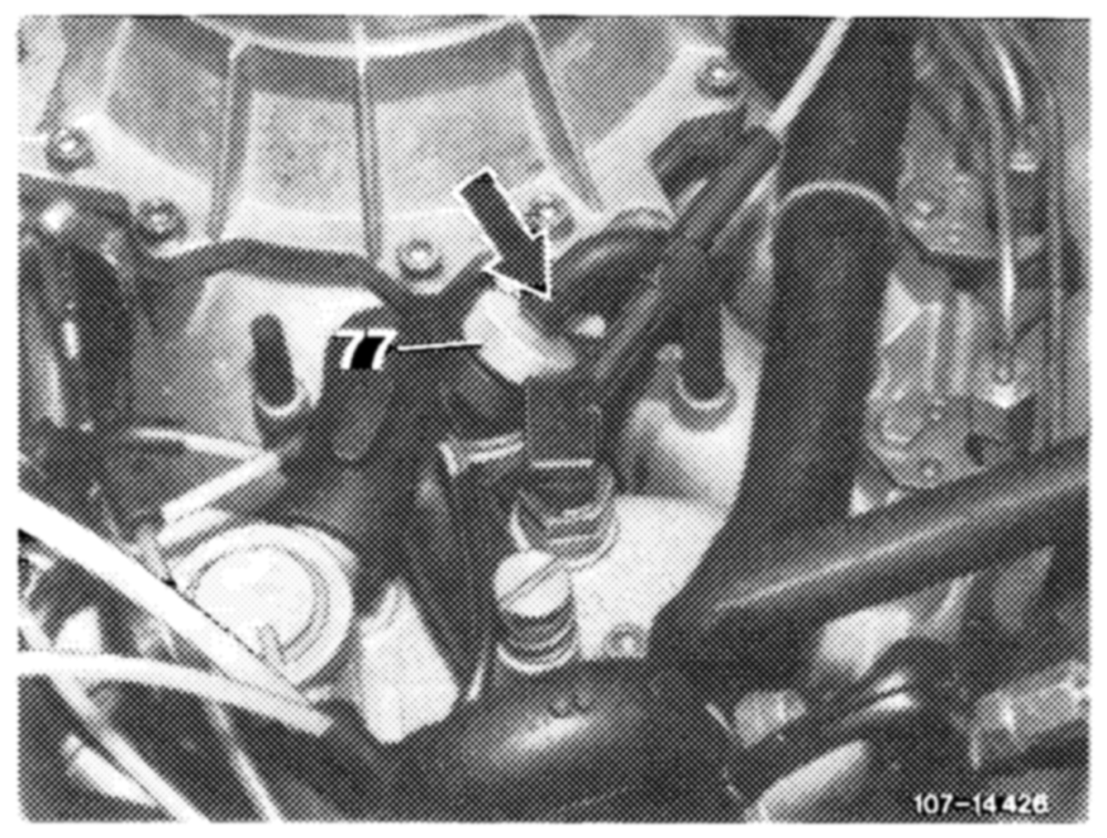
starting 1978, (CS) starting 1978
Check idle speed emission value without air injection. For this purpose, pull vacuum hose (arrow) from retarding valve (77) and close hose. This will disconnect air injection.
@ ©
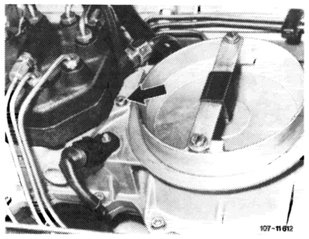
18 Adjust idle speed emission value. For this purpose, unscrew closing plug (arrow).
07.3.1 la—110/12, F2
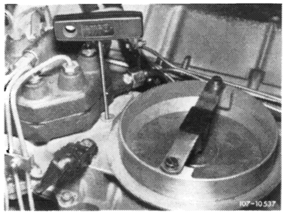
Insert screwdriver through bore into socket of idle speed mixture regulating screw and adjust emission value by turning screw.
Turning counterclockwise = leaner
Turning clockwise richer I
Hold bore for closing plug closed. Accelerate for a short moment, check idle speed emission value once again and adjust, if required. Put back closing plug.
Plug back vacuum line with version on thermovalve, with version on time-delay valve.
Check idle speed emission value once again (air injection in operation). The idle speed emission value should be below previously set value.
19 Mount air cleaner. Check idle speed and idle speed emission value once again and adjust, if required.
20 Move selector lever into driving position, switch on air-conditioning, turn power steering to full lock with engine running smoothly. Adjust speed, if required.
07.3.1 la—110/13, F2