General description of breaker-controlled transistorized ignition
WIS 07.5-519
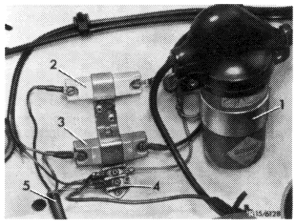
Layout of transistorized ignition
The system comprises: Switchgear Ignition coil (1) Series resistance 0.4 ohm (3) Series resistance 0.6 ohm (2)
Operation
The ignition coil current is switched on by a transistorized system instead of the contact breaker point. The contact breaker point serves to control this transistorized system.
The switching transistor is energized when the contact breaker point is closed. When the contact breaker point opens, the transistor locks and the ignition coil current is interrupted. The interruption of the circuit in the primary winding induces the ignition voltage in the secondary winding similar to the conventional coil ignition.
To increase the ignition voltage when starting, the 0.4 ohm series resistance is bridged by contact 16 on starter.
Switchgear (1)
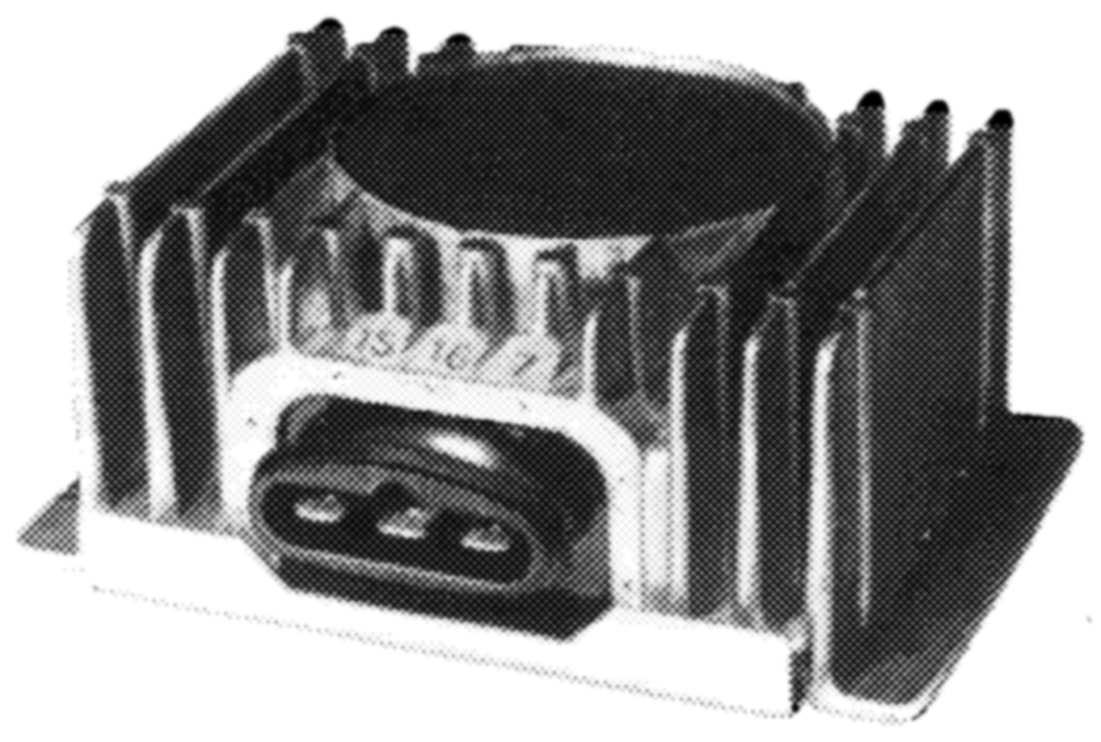
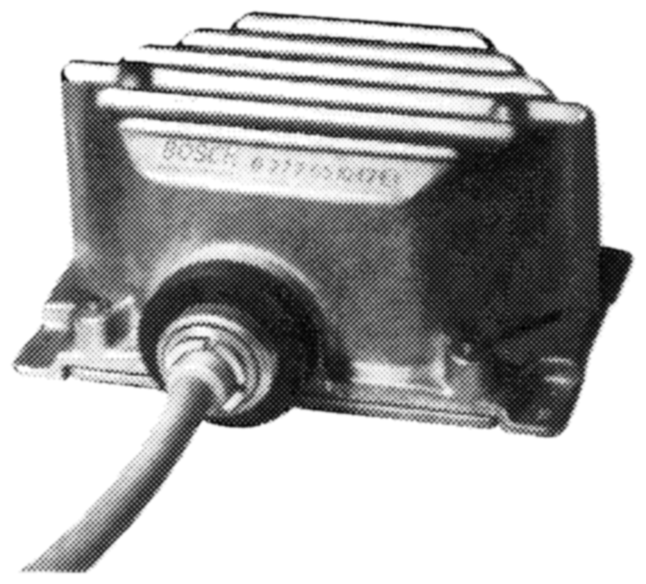
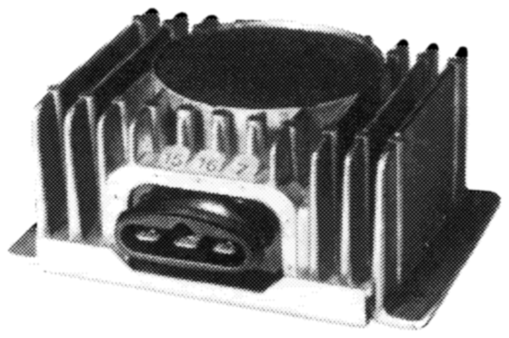
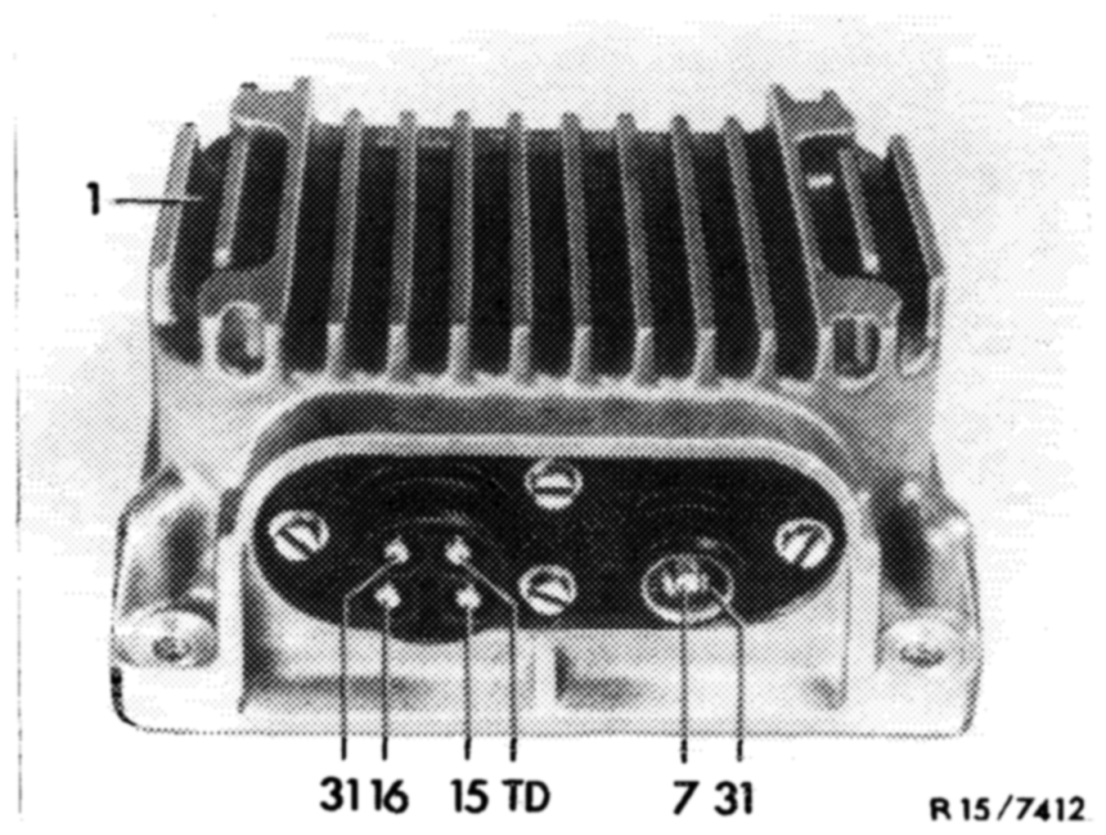
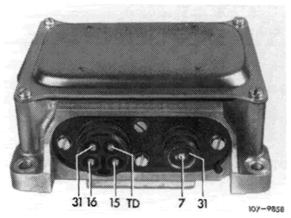
The switchgear comprises several transistors, resistors and other electronic components in a metal housing, depending on type. The housing protects these components against mechanical damage and splash water and serves simultaneously to dissipate electric heat. Contact on switchgear is made by means of a 3-point flat plug connection or a 4-point round plug connection with separate coaxial connection for establishing contact.
Switchgears for model 107 (wheel house units) are provided with a firmly attached connecting line.
In the event of repairs, only the entire switch-gear can be exchanged.
Ignition coil (2)
The ignition coil design and its external dimensions are similar to a normal heavy-duty ignition coil. But the winding system is different. The interturn ratio is approx. 1 : 185 as compared with 1 : 100 on conventional ignition coils.
External identification: blue paintwork.
Series resistances
Resistances 0.4 ohm and 0.6 ohm are similar to ignition coil resistances used up to now: a ceramic body encloses the resistance winding with its extended connections.
For attachment, the ceramic body is provided with a sheet-metal clamp. The color of this clamp indicates the resistance value, which is additionally punched in as a number.
| Color | Code number | Resistance |
| anodized, blue anodized, metallic | 0.4 0.6 | 0.4 ohm 0.6 ohm |
General information
On vehicles with transistorized ignition systems do not operate engine when battery is not connected.
When using rapid chargers for charging the vehicle battery, separate battery from other vehicle circuits.
Starting assistance with rapid chargers is not permitted.
When installing battery, pay attention to correct polarity.
Do not interchange line connections on switchgear (e.g. when switchgear is tested in removed condition).
Switchgear may suffer damage, if these instructions are not observed.
Instructions for test jobs
On engines with transistorized coil ignition, speed and closing angle (dwell angle) cannot always be measured in the usual manner.
Depending on type of tester used, connection must be made at varying points of ignition system. In each case, the operating instructions of test instrument apply. To facilitate connection of speed and dwell angle test instruments, an empty, offset cable shoe is screwed on under cable connector 7.
TSZ (transistorized) switchgear with Ge transistor
Bosch no. installed in model
0 227 051 006* 108.057/058 0 227 051 008* 0 227 051 011* 109.056 0 227 057 015 111.026/027
* Install 0 227 051 015 as a replacement.
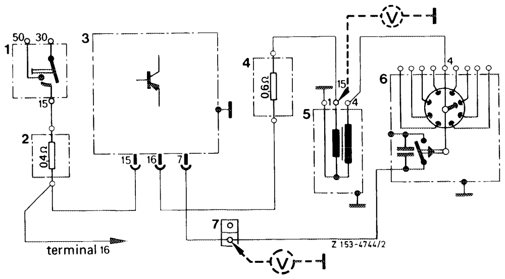
Wiring diagram
Ignition starting switch NOOBWN— Series resistance 0.4 ohm Switchgear Series resistance 0.6 ohm Ignition coil Ignition distributor wee eri Cable connector terminal 7 (TD)
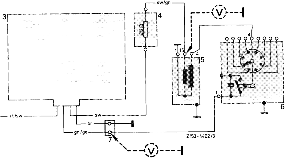
Designation of 3-core connecting line on switchgear (3):
black terminal 16 (to series resistance 0.6 ohm)
red/black terminal 15 (to series resistance 0.4 ohm)
green/yellow terminal 7 (to cable connector terminal 1 ignition distributor)
Switchgear 0 227 051 015
TSZ switchgear (wheel house units) with Ge transistor or Si transistor
Installed in model Bosch no.
0 227 051 012* 107.023 0 227 051 017* 107.024 up to December 1974 107.043 107.044 107.024/044@s* up to including model year 1974
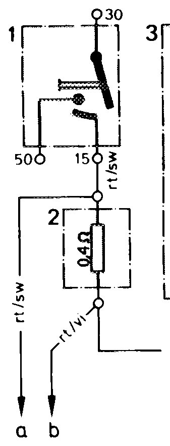
*Replaced by Si wheel house unit 0 227 051 022.
Wiring diagram
NOORWNS Ignition starting switch Series resistance 0.4 ohm Switchgear Series resistance 0.6 ohm Ignition coit Ignition distributor Cable connector Terminal 7 a To diagnosis plug b Starter Terminal 16 br = brown ge = yellow gn = green rt = red sw = black vi = purple
Switchgear 0 227 051 017 107 – 8815,
TSZ switchgear with Si transistor
Bosch no. Installed in model
0 227 051 013* 108.067/068 0 227 051 016 109.057
* Install O 227 051 016 as a replacement.
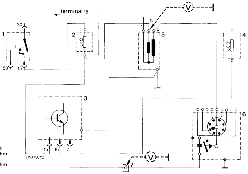
Wiring diagram
1 Ignition starting switch
2 Series resistance 0.4
3 Switchgear
4 Series resistance 0.6
5 Ignition coil
6 Ignition distributor
7 Cable connector, terminal 7
Switchgear 0 227 051 016 107 – 8814
TSZ switchgear — standard switchgear —- with Si transistor
Bosch no. Installed in model
Mecclosst up to November 1974 116.028/029
0 227 051 014 116.032/033 @s®up to including model year 1974
107.043/044 Meosziosst starting December 1974 107.023/024 116.028/029
0 227 051 024 107.024/044 @sa starting model year 1975 116.032/033
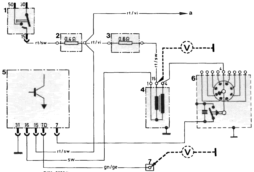
Wiring diagram
NOORWN= Ignition starting switch Series resistance 0.4 ohm Series resistance 0.6 ohm Ignition coil Switchgear Ignition distributor Cable connector with test terminal TD a To terminal 16 starter yellow miowun green red my black \ purple 2153 -5056/4
Switchgear 0 227051014
Switchgear 0 227 051 024