WIS 05-330
WIS 05-330
Tightening torques
Nuts for cylinder head cover
Necked-down screw for camshaft sprocket
Spacial tools
(_. Impact puller for bearing bolt (basic unit) gy – 116 589 20 33 00
Threaded bolt M 8, 150 mm long “ps nope -e207 for impact puller – 616 589 00 34 00
— Puller for bearing bolt – 115 589 20 33 00
Threaded bolt M 8 x 60 sup for puller – 123 589 00 34 00
Socket 27 mm, 1/2’ square, Lo for rotating engine 00%. 6199 – 001 589 65 09 00
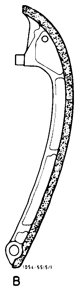
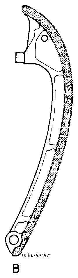
Note There are two tensioning rail versions for these engines. The second tensioning rail version (B) can also be installed in engines with first tensioning rail version (A).
A 1st tensioning rail version B_ 2nd tensioning rail version
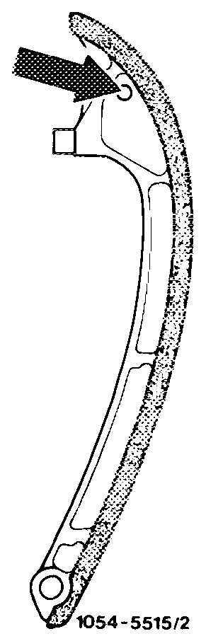
To avoid mixing up with tensioning rai! of diesel engines, the respective tensioning rails were designed with special characteristics.
The tensioning rail of diesel engines runs to a point at upper end and has an 8 mm bore at that end (arrow).
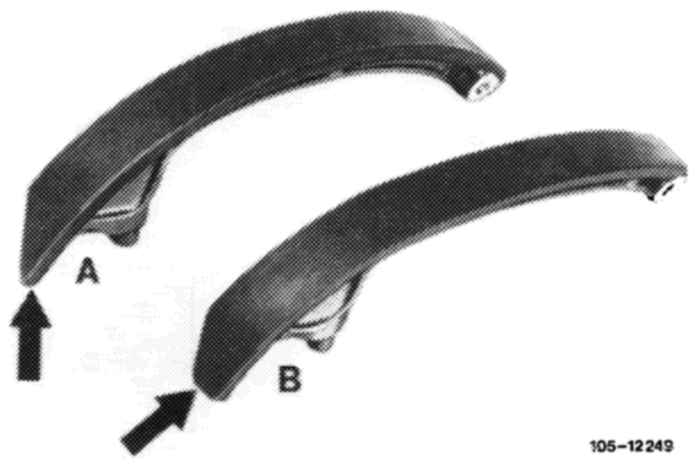
The tensioning rail of the engines described here are wider at their upper end and there is no bore at that end.
A. Tensioning rail diesel engines B_ Tensioning rai! gasoline engines
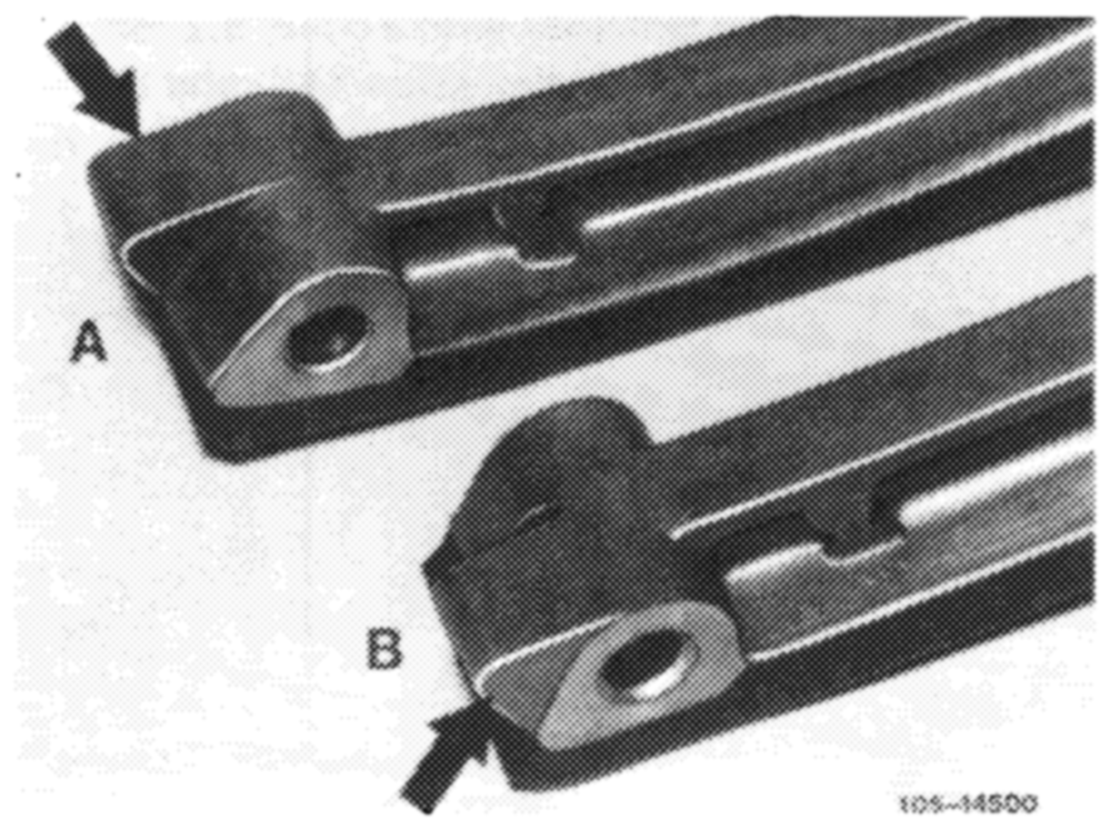
By now, the upper end of the tensioning rails have been provided with a cast lug which prevents any confusion.
The lug is located on tensioning rail of diesel engines in direction of cylinder 1 and on tensioning rail of the engines described here in direction of balancing disc.
A Tensioning rail diesel engines B_ Tensioning rail gasoline engines
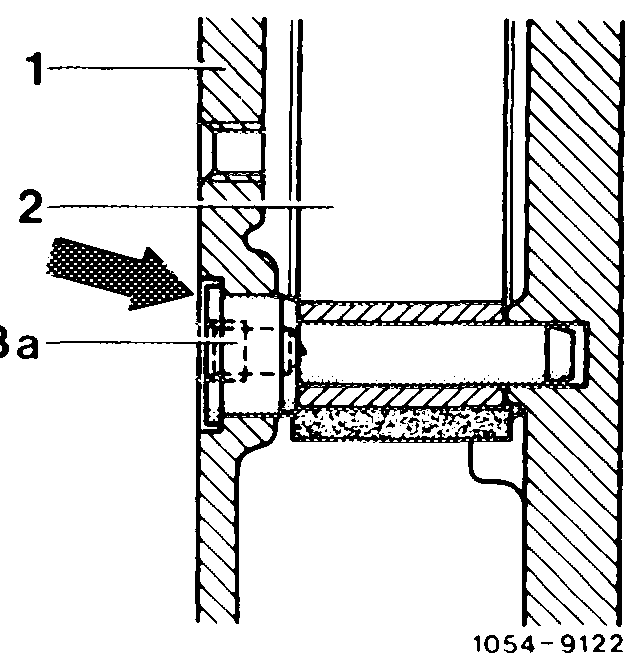
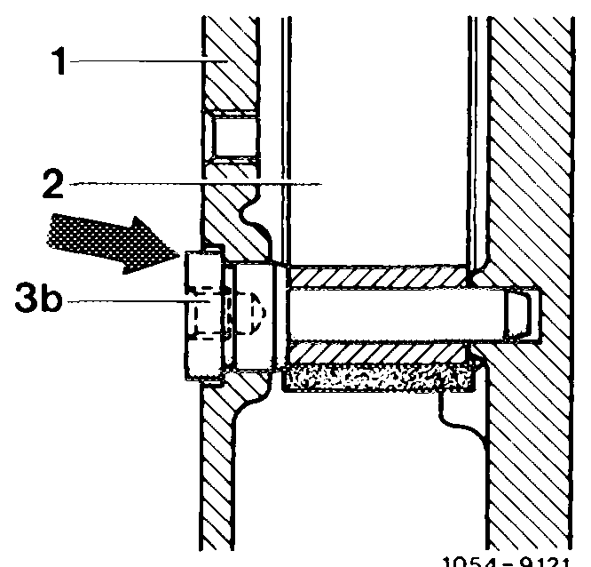
For reasons of standardization, the same bearing bolt is installed on the tensioning rail as on diesel engines 615, 616 and 617, part No. 615 052 04 17 as from the end of 1979.
wo
Former version 1 Cylinder crankcase 2 Tensioning rail 3a Bearing bolt
Changed version 1 Cylinder crankcase 2 Tensioning rail 3b Bearing bolt
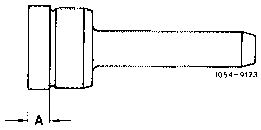
This bearing bolt is provided with a collar 5.2 mm high (formerly 2.4 mm — dimension ‘‘A‘’) and therefore is projecting on the cylinder crankcase (formerly flush).
Former version “A’’ = 2.4 mm Changed version “A” = 5.2 mm
When removing and installing tensioning rail, and in the presence of oil leaks on bearing bolt, therefore, take account of collar height prior to trying to knockin bearing bolt flush (may result in damage to cylinder crankcase).
The bearing bolt with higher collar may be installed instead of the former version. Only the changed version will be supplied from now on.
Removal
1 Remove radiator and fan.
2 Onengines 115.923/926/951 with tensioning rail version (A), remove chain tensioner (05-310).
On engines with light alloy tensioning rail (B), push back thrust bolt of chain tensioner.
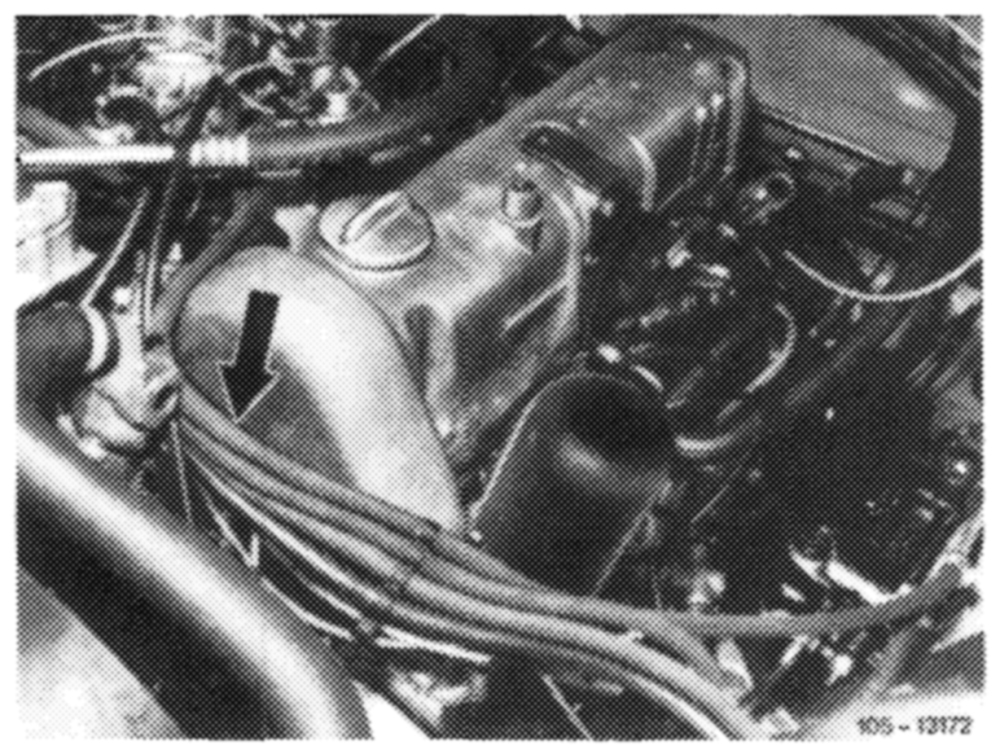
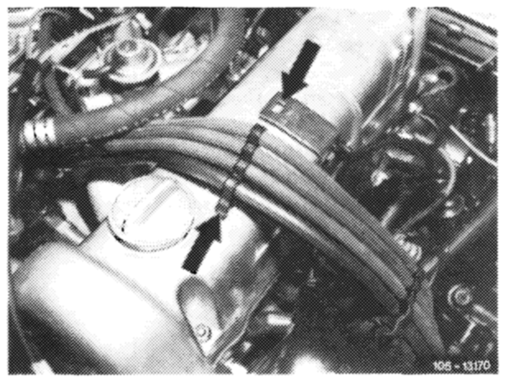
3 Remove cylinder head cover. For this purpose, for @s) , GD, Cand GsAstarting 1977, push out clamp assembly of fuel hoses on holder and pull out fuel hoses with clamp assembly in forward direction over cylinder head cover.
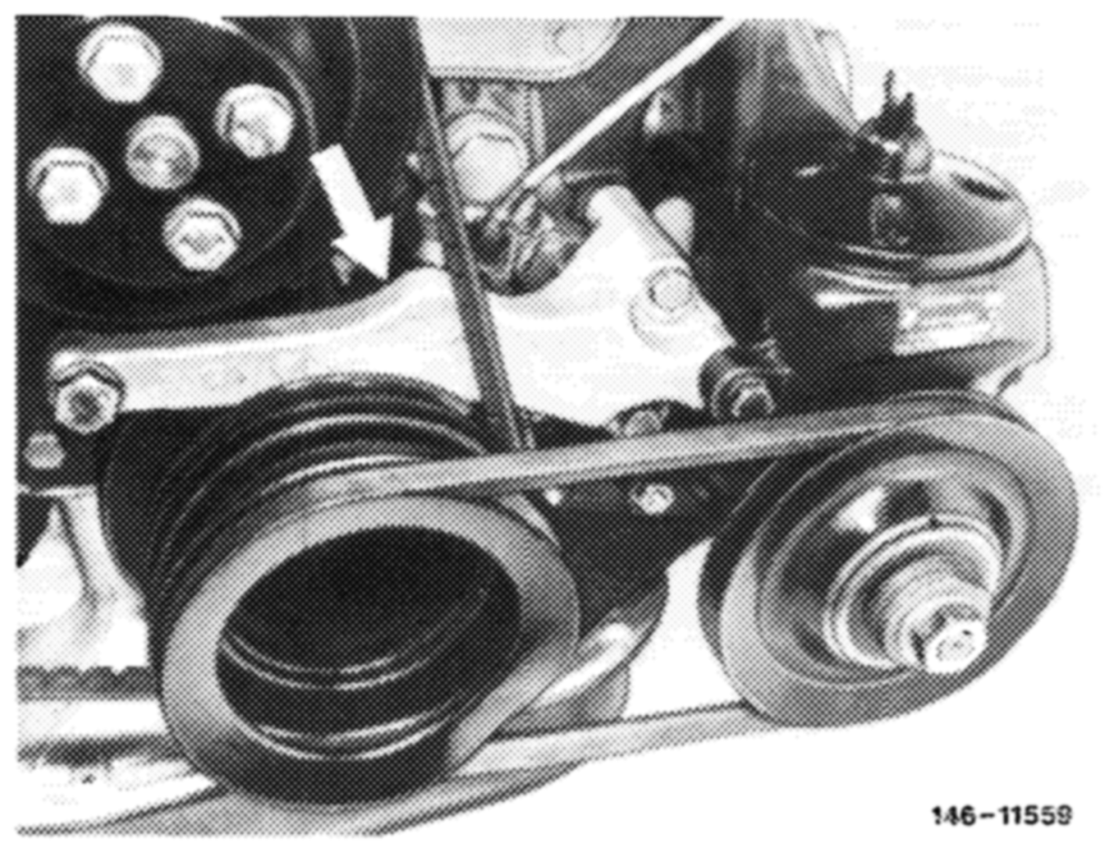
4 On vehicles model 123 with power steering, remove aluminum carrier of power steering pump (arrow).
Note: Not applicable for @us), G), CS) and Gs) starting 1977.
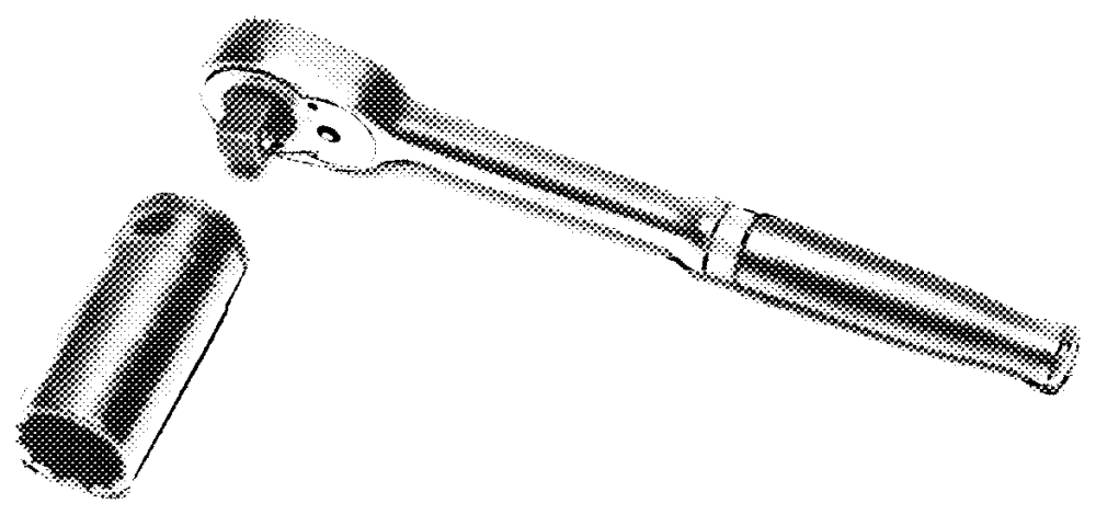
5 Rotate crankshaft with tool combination until recess in balancing disc is in front of bearing bolt of tensioning rail (Fig. item 8).
R 100/6498
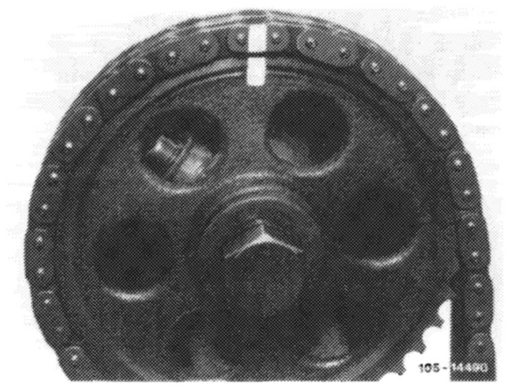
6 Mark camshaft sprocket and timing chain in relation to each other.
7 Remove camshaft sprocket.
To loosen necked-down screw, apply counterhold to camshaft sprocket with a screw driver or steel pin, loosen holder for fuel lines and swivel sideways.
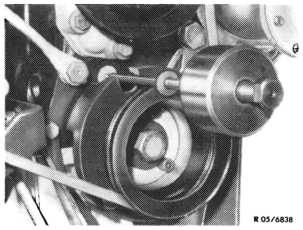
8 Knock out bearing bolt with impact puller. Unscrew pulley, if required.
Attention!
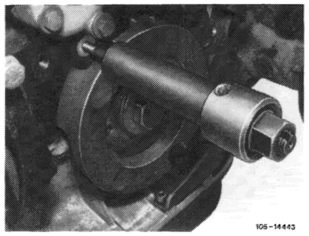
If the bearing bolt is seated so tightly that it cannot be knocked out with impact puller, use puller part No. 115 589 20 33 00. Unscrew pulley first.
9 Remove tensioning rail.
10 Renew badly worn tensioning rails and bearing bolts.
Installation
11 Coat bearing bolt on collar with sealing compound.
12 Position tensioning rail and knock-in bearing bolt by means of impact puller.
13 Place camshaft sprocket with timing chain on camshaft while paying attention to color code markings.
14 Position necked-down screw for fastening camshaft sprocket and tighten to 80 Nm. For this purpose, apply counterhold to camshaft sprocket with screw driver or steel pin.
15 For further installation proceed vice versa to removal.