WIS 05-210
WIS 05-210
5—210 Inspection and adjustment of valve clearance
Valve clearance with engine cold (approx. 20 °C) with engine warm (60 °C + 15 °C)
Intake 0.10′) 0.15!)
Exhaust 0.20 0.25
1) 0.05 mm higher during lasting outside temperatures below —20 °C.
Tightening torques Nm
Valve adjusting screws 20–40
Nuts for cylinder head cover 15
Special tools
Valve adjusting wrench 17 mm, 1/2″ square – 110 589 00 01 00
= == Slip gauge holder red oon. eaee – 617 589 00 40 00
0.10 mm thick Slip cauce plates 0.15 mm thick 617 589 01 23 00 p gauge P 0.20 mm thick „006-6369 117 589 00 23 00 0.25 mm thick 117 589 01 23 00 – 617 589 00 23 00
Socket 27 mm, 1/2” square, . . for rotating engine – 001 589 65 09 00
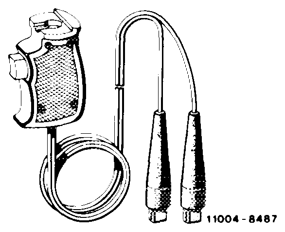
Contact handle for rotating engine (component of compression pressure recorder (compressometer) 001 589 46 21 00) – 001 589 46 21 08
Note Check valve clearance with engine cold or warm and adjust, if required.
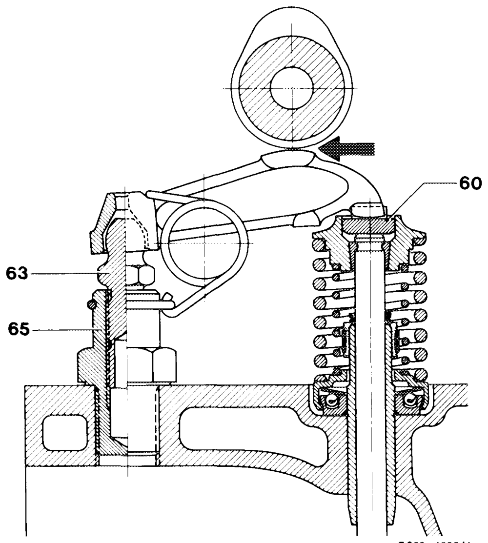
If adjustment is no longer possible, renew thrust piece (60), available at varying thickness (refer to spare parts data).
If the torque of the adjusting screw (63) is below 20 Nm, renew adjusting screw (63) or adjusting screw (63) with threaded bushing (65).
Adjustment
1 Check valve clearance between sliding surface of rocker arm and cam base circle of camshaft (arrow). Tip of camshaft should be vertical in relation to rocker arm.
Valve clearance is correctly set, when pulling of slip
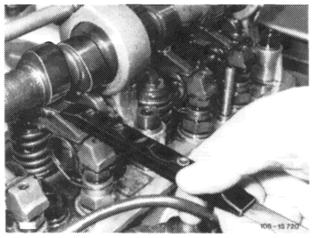
gauge blade requires some effort.
Observe layout of intake and exhaust valve. a —~\
4 1 3 4 2 T intake N\_/ t exhaust
The engine can be rotated as follows:
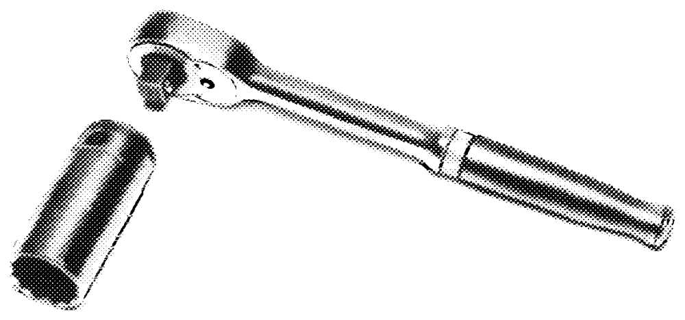
a) with tool combination on crankshaft front.
Attention! Do not rotate engine at fastening bolt of camshaft sprocket.
Do not rotate crankshaft backwards.
R 100/6498
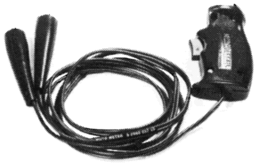
b) with starter and contact handle.
On model 115, connect contact handle to battery + and to starter terminal 50.
Terminate cable at ignition coil terminal 1.
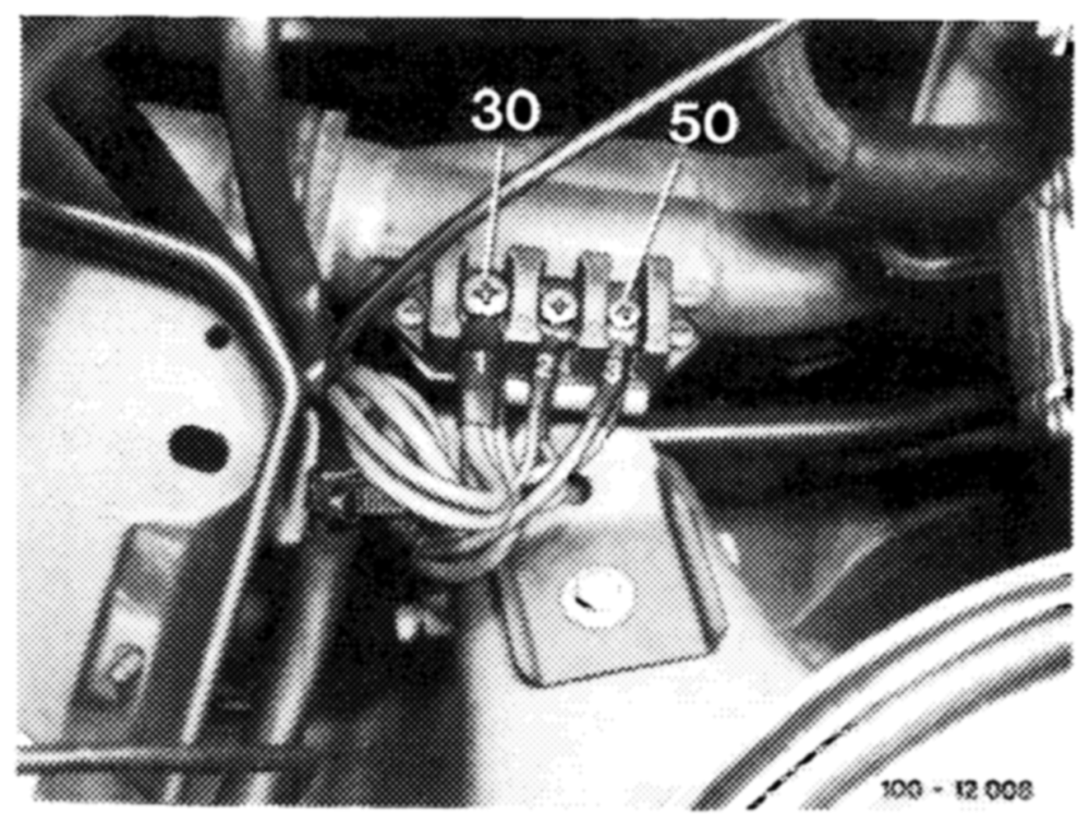
On model 123, connect contact handle to terminal 30 and terminal 50 to cable connector.
Terminate cable on ignition coil terminal 1.
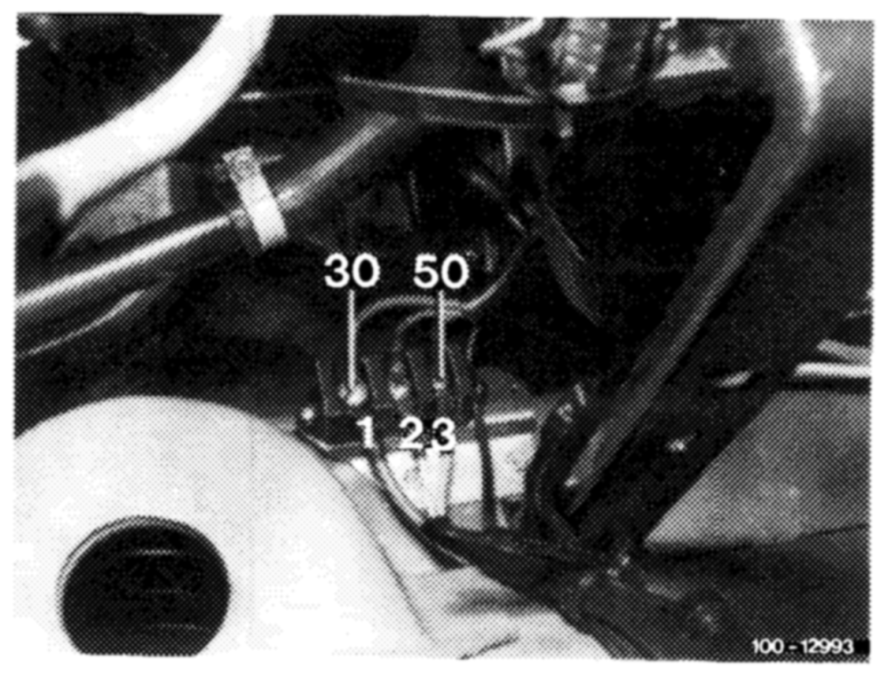
lefthand steering
righthand steering
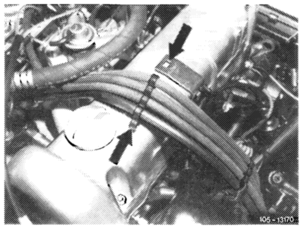
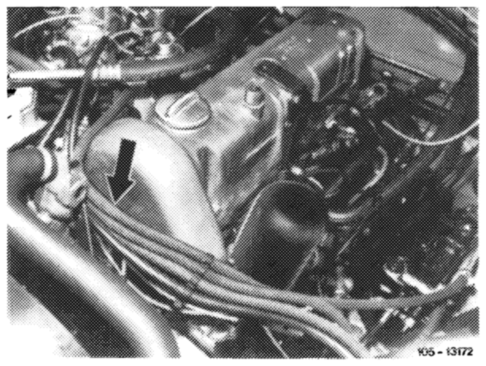
2 Remove cylinder head cover. For this purpose, on , G), Gand Gs) starting 1977, push out clamped assembly of fuel hoses on holder and pull down fuel hoses with clamp assembly in forward direction over cylinder head cover.
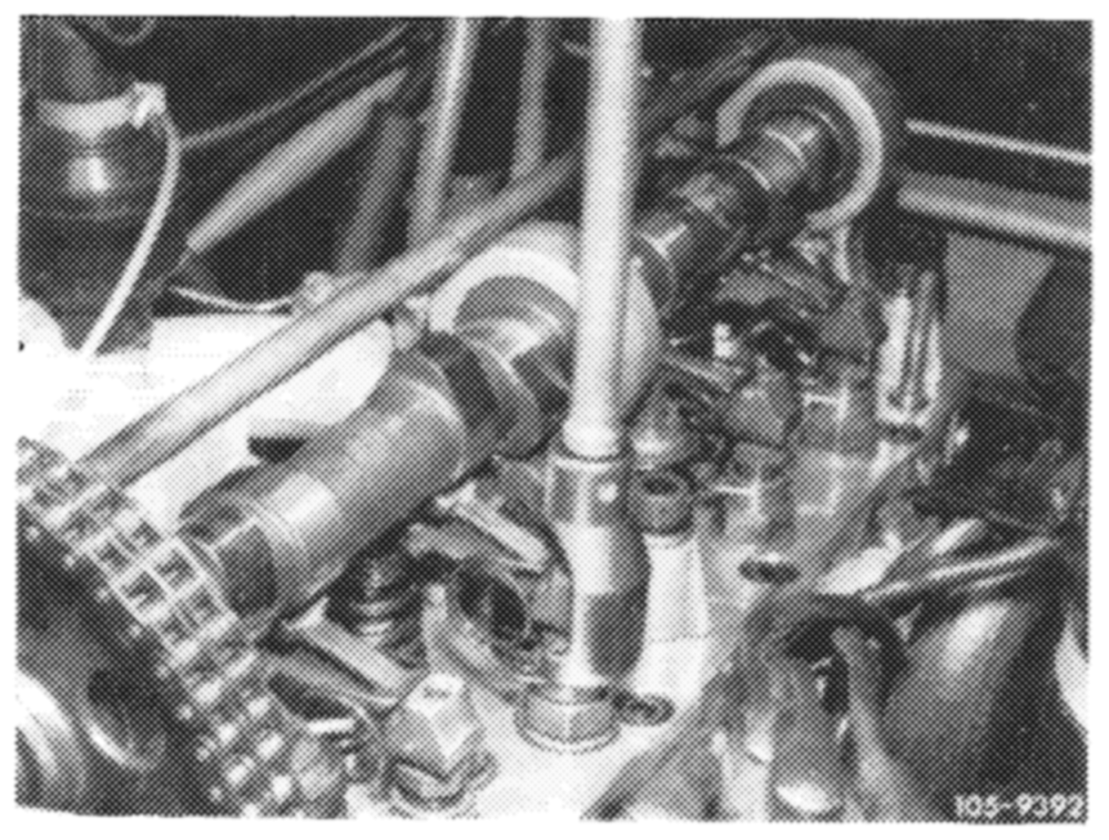
3 Adjust valve clearance by turning adjusting screw with valve adjusting and torque wrench.
4 Prior to mounting cylinder head cover, check gasket and renew, if required.