Renewal of threaded bushing with valve adjusting screw
WIS 05-212
with engine cold (approx. 20 °C) with engine warm (60 °C + 15 °C) Valve clearance
0.10′) 0.15′) Intake
Exhaust 0.20 0.25
1) 0.05 mm higher during lasting outside temperatures below —20 °C.
Tightening torques Nm
Nuts for cylinder head cover 15
Threaded bushing in cylinder head 80
Valve adjusting screw 20–40
Special tools Pressure lever for valve spring – 123 589 03 61 00
Valve adjusting wrench 17 mm, 1/2’ square – 110 589 00 01 00
Socket 27 mm, 1/2’ square, for rotating engine – 001 589 65 09 00
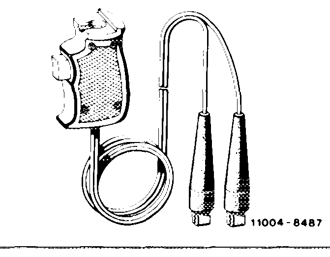
Contact handle for rotating engine (component of compression pressure recorder (compressometer) 001 589 46 21 00) – 001 589 46 21 08
Note If the torque of the valve adjusting screw is below
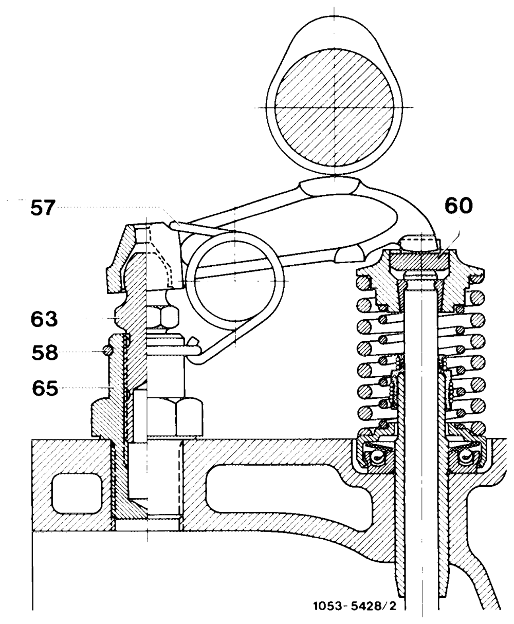
20 Nm, renew valve adjusting screw (63) or threaded bushing (65) with valve adjusting screw (63).
57 Tensioning spring 58 Annular spring 60 Thrust piece 63 Valve adjusting screw 65 Threaded bushing
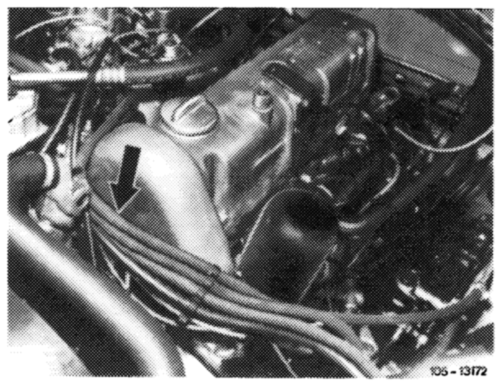
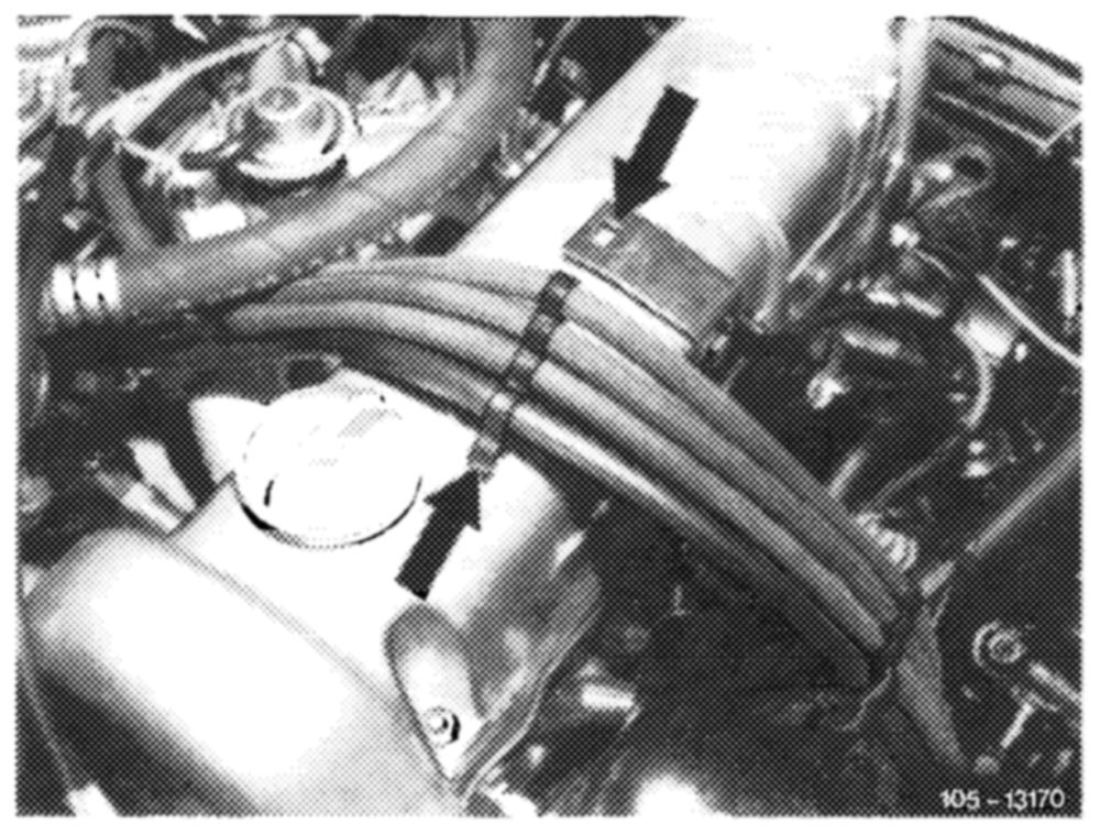
1 Remove cylinder head cover. For this purpose, on @s) , G), Cand Gs) starting 1977, push out clamp assembly of fuel hoses on holder and push down fuel hoses with clamp assembly in forward direction over cylinder head cover.
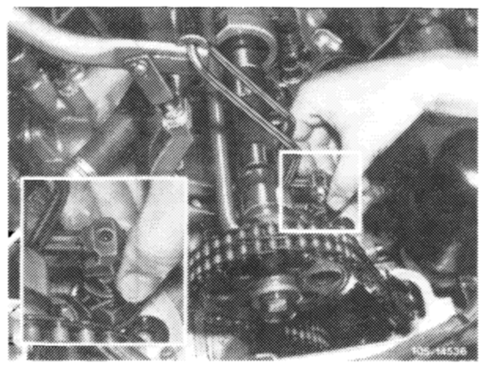
2 Remove rocker arm (05—230).
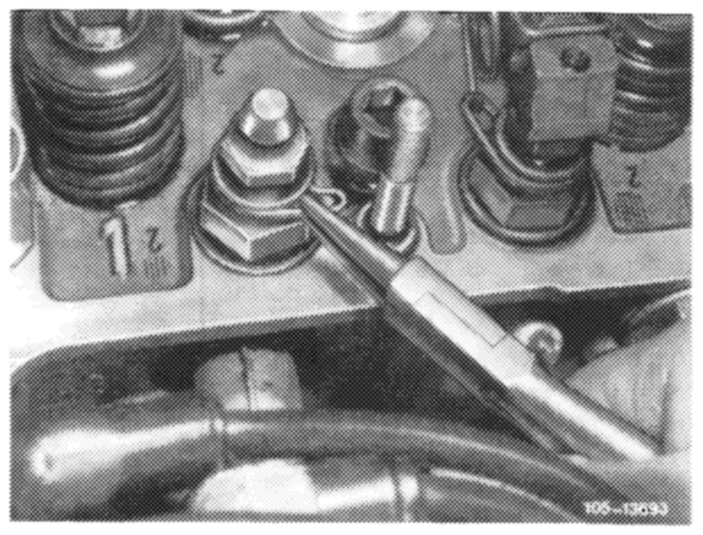
3 Pull off annular spring.
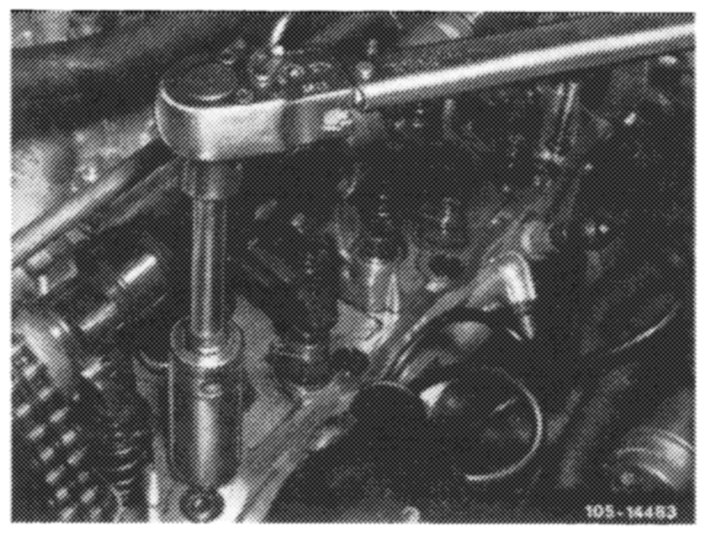
4 Unscrew threaded bushing with valve adjusting screw.
5 Coat threads of threaded bushing with tallow.
Screw-in threaded bushing with valve adjusti:1g screw and tighten to 80 Nm.
Attention! The threaded bushing should not cut shavings when screwed in.
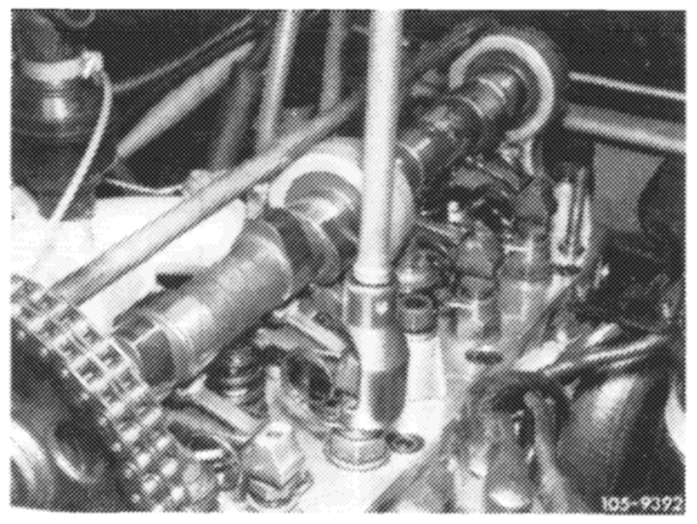
6 Insert annular spring.
7 Install rocker arm (05—230).
8 Adjust valve clearance (05-210).