WIS 22-220
WIS 22-220
Tightening torques Nm
Nut (32) to front engine stop (reference value) Model 115 90
Adjusting screw (31) to front engine stop Model 123 130
Model 123 40 Adjusting screw (11) on rear engine mount Model 115 30
Special tools
Torque wrench with inserting ratchet, 1/2″ square, 25–130 Nm <= – 001 589 66 21 00
Torque wrench with inserting ratchet, 2 1/2″ square, 40–200 Nm – 001 589 67 21 00
Self-made tool
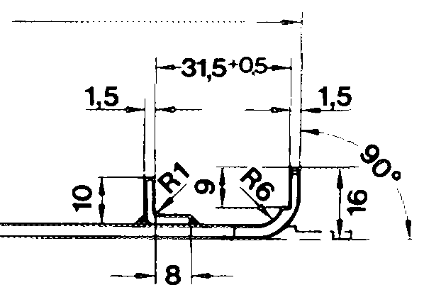
= — 148
14 _ or
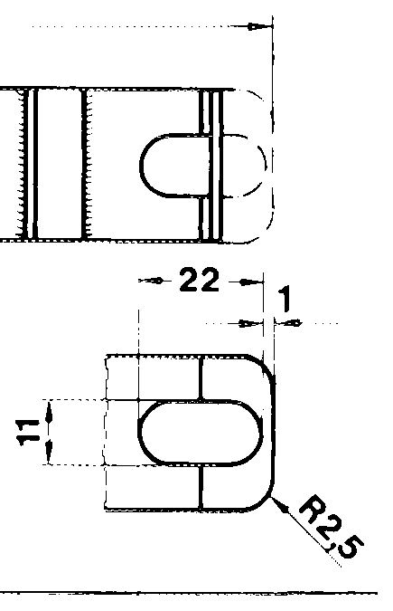
B57 — 158 — Gauge for adjusting front engine stop, a _ mode! 123 2 tos
Note Vehicle should rest on its wheels ready for driving.
Engine stops must not be treated with grease or oil,
since this will result in destruction of rubber and/or in separation of the plastic lamellae vulcanized-in.
Model 115
Adjustment
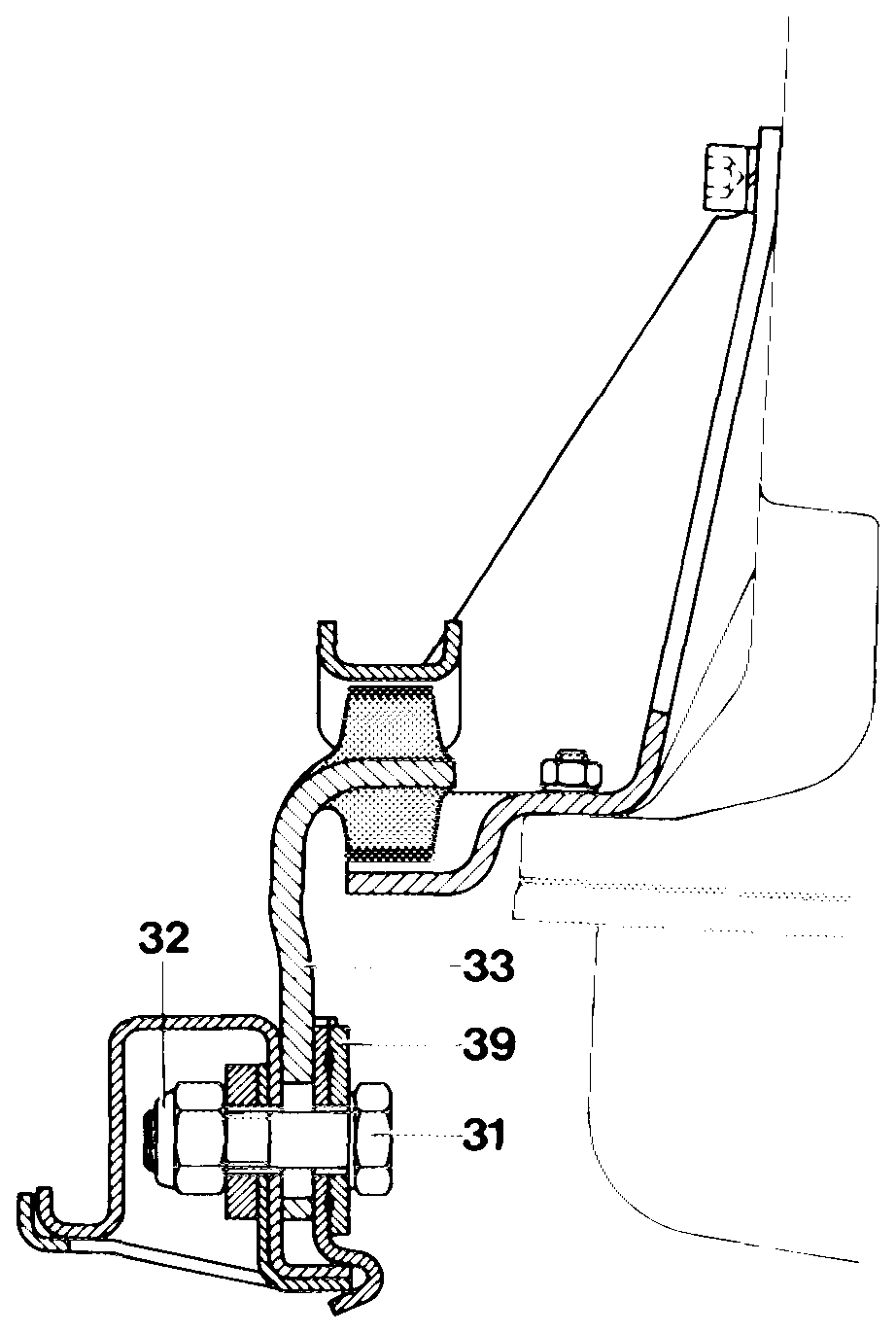
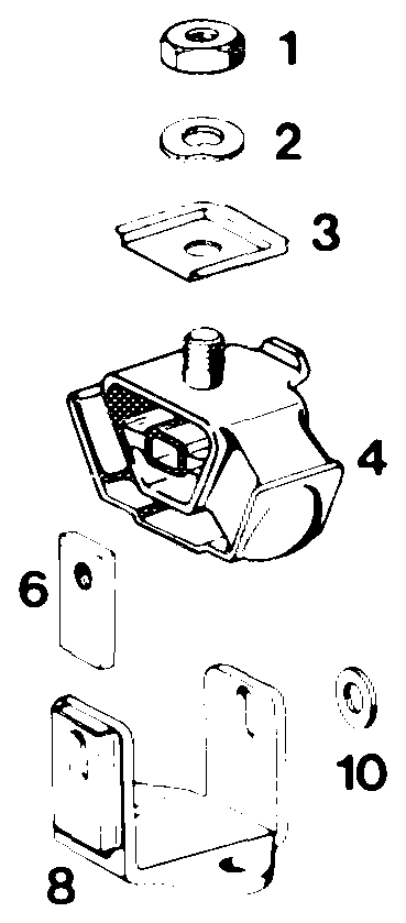
Front engine mount model 115.015
1 On model 115.015, completely loosen nut (32) on front engine stop.
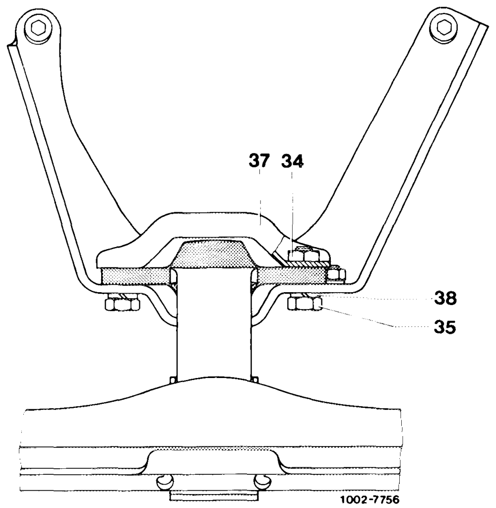
2 On all models (except model 115.017 with manual transmission), completely loosen adjusting screw (11) on rear engine mount.
3 Move engine by lightly shaking crosswise manually.
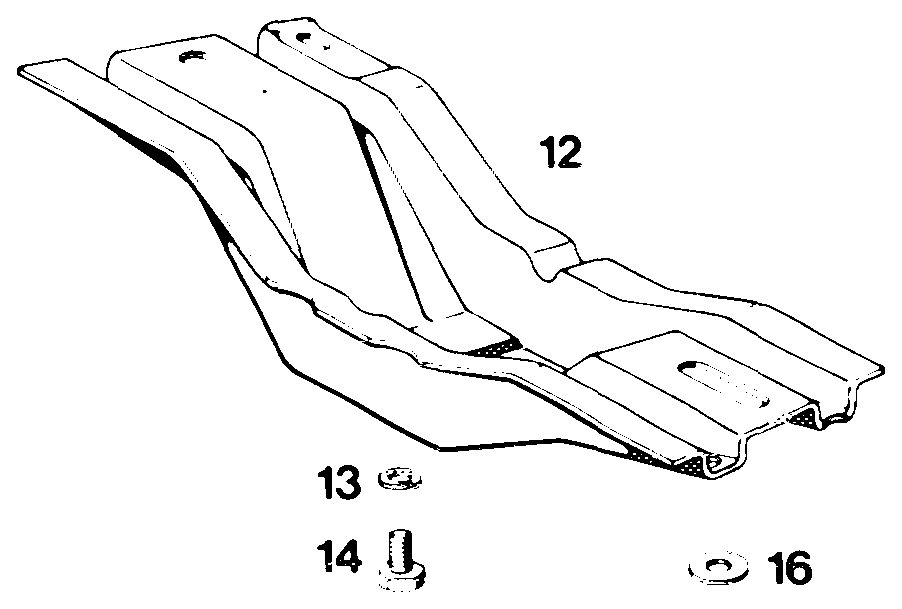
4 Tighten adjusting screw (11) and nut (32) to specified torque.
Note: Torque wrench cannot be positioned against nut (32).
Rear engine mount with stop
Model 123
Adjustment
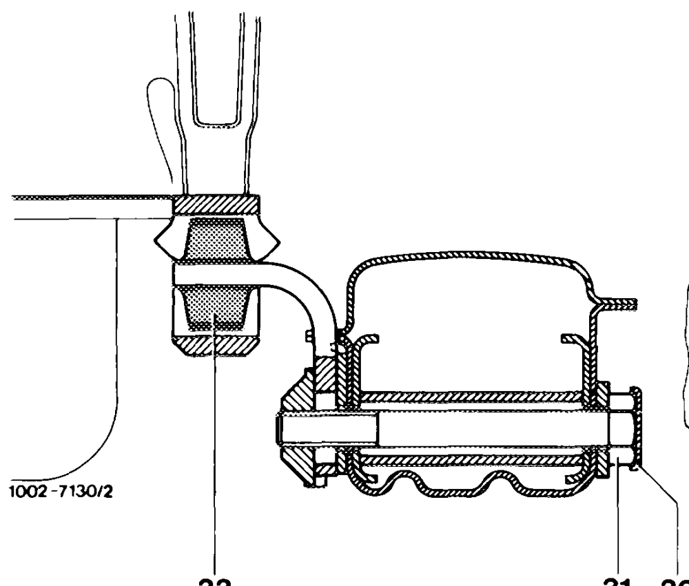
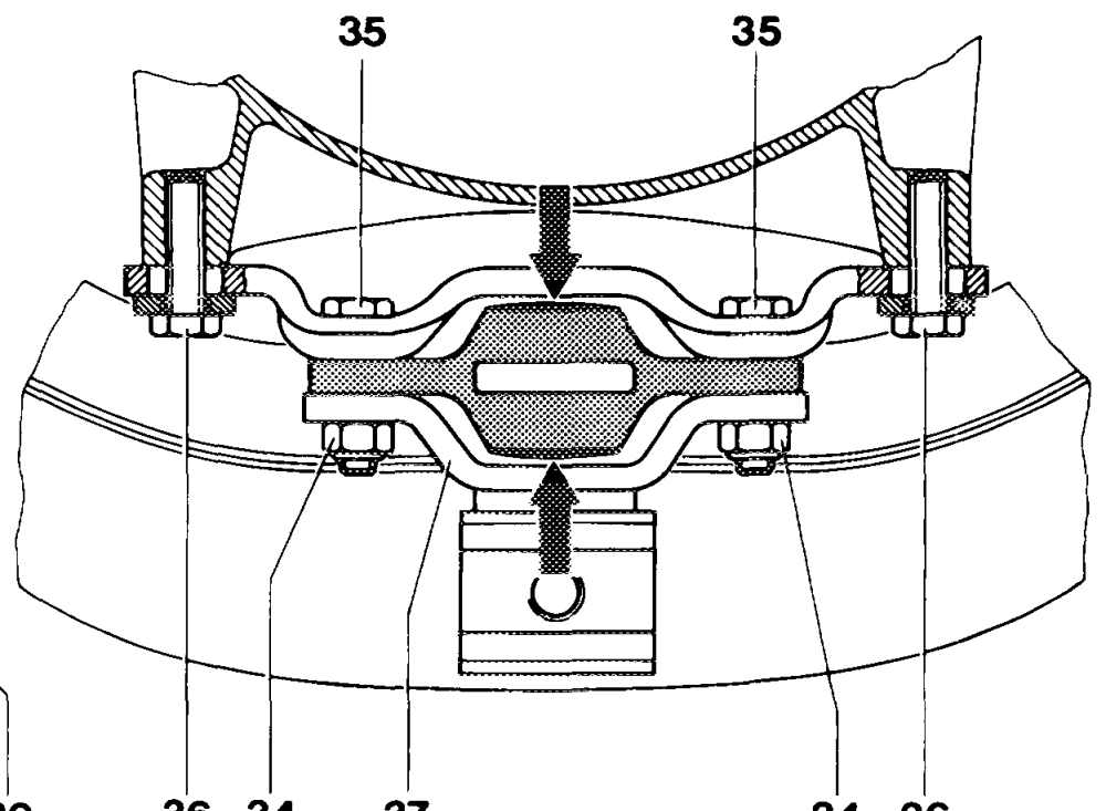
Front engine stop
33 31 30 36 34 37 34 36
1 Completely turn steering to the left or right.
2 Lift lock (30) on front engine stop and swivel away in lateral direction. Completely loosen adjusting screw (31).
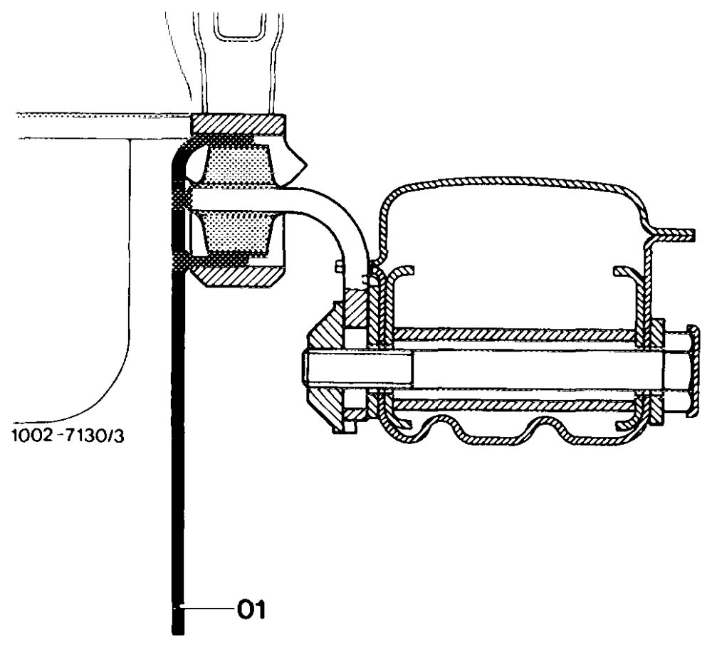
Note: Loosen engine stops sticking to frame cross member by wax and paint.
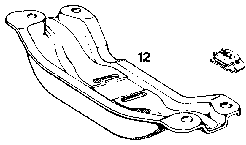
3 Completely unscrew adjusting screw (11) on rear engine mount (figure item 6).
4 Insert self-made gauge (01) at front engine stop.
5 Move engine by lightly shaking crosswise manually.
6 Tighten adjusting screw (11) at rear engine mount to specified torque.
7 Tighten adjusting screw (31) at front engine stop to specified torque and secure by lock (30).
8 Lift-off self-made gauge.
Rear engine mount with stop on vehicles with automatic transmission 1003-7334: