Removal and installation of engine shock absorber
WIS 22-240
Note Model 115.017 generally and model 123 with automatic transmission are provided with an engine shock absorber.
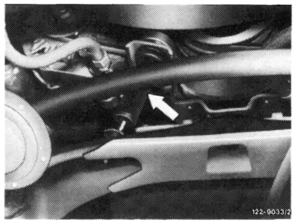
On model 123, the engine shock absorber has not been installed at start of series, but some time later.
On vehicles manufactured earlier, about which customers have complaints with regard to vibrations (spluttering), the engine shock absorber can be subsequently installed (22–241).
The above does not apply to vehicles with manual transmission.
Model 115.017
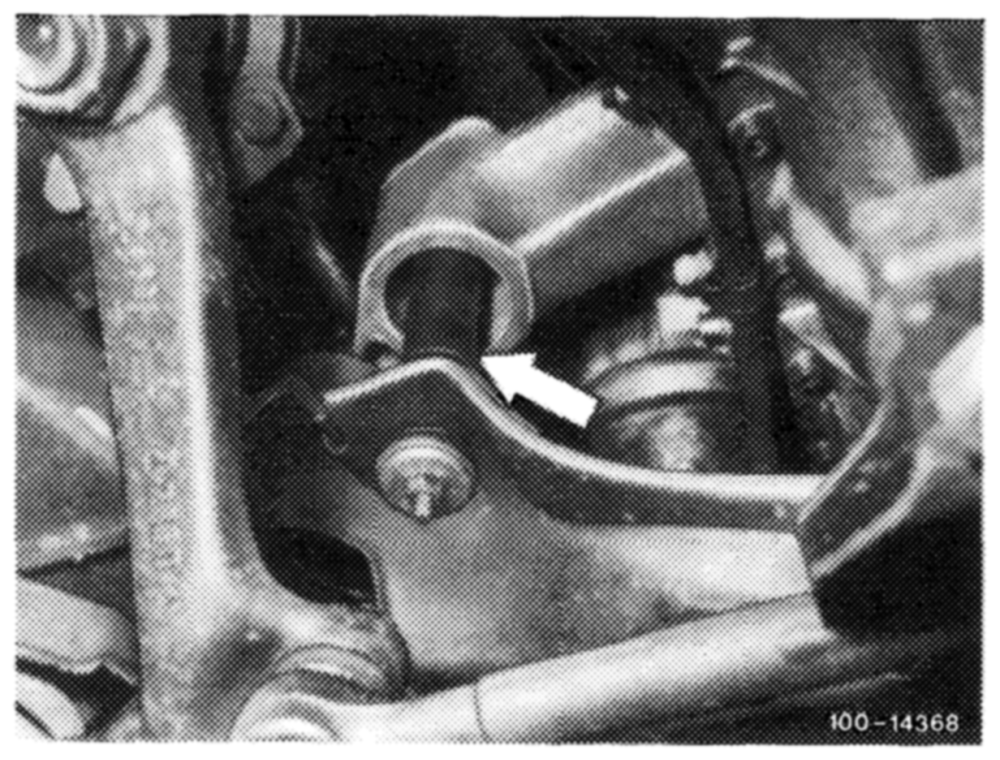
On model 115.017 the engine shock absorber is mounted at front right in driving direction, and on model 123 at the left between engine mount and cross member.
Model 123
Model 115.017
Removal
1 Unscrew nuts (40).
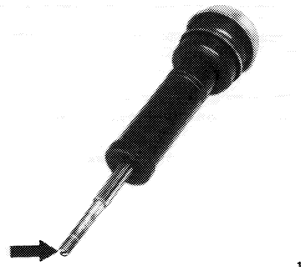
For unscrewing lower nut, apply counterhold to piston rod by means of a screw driver at spot provided (fig. item 5).
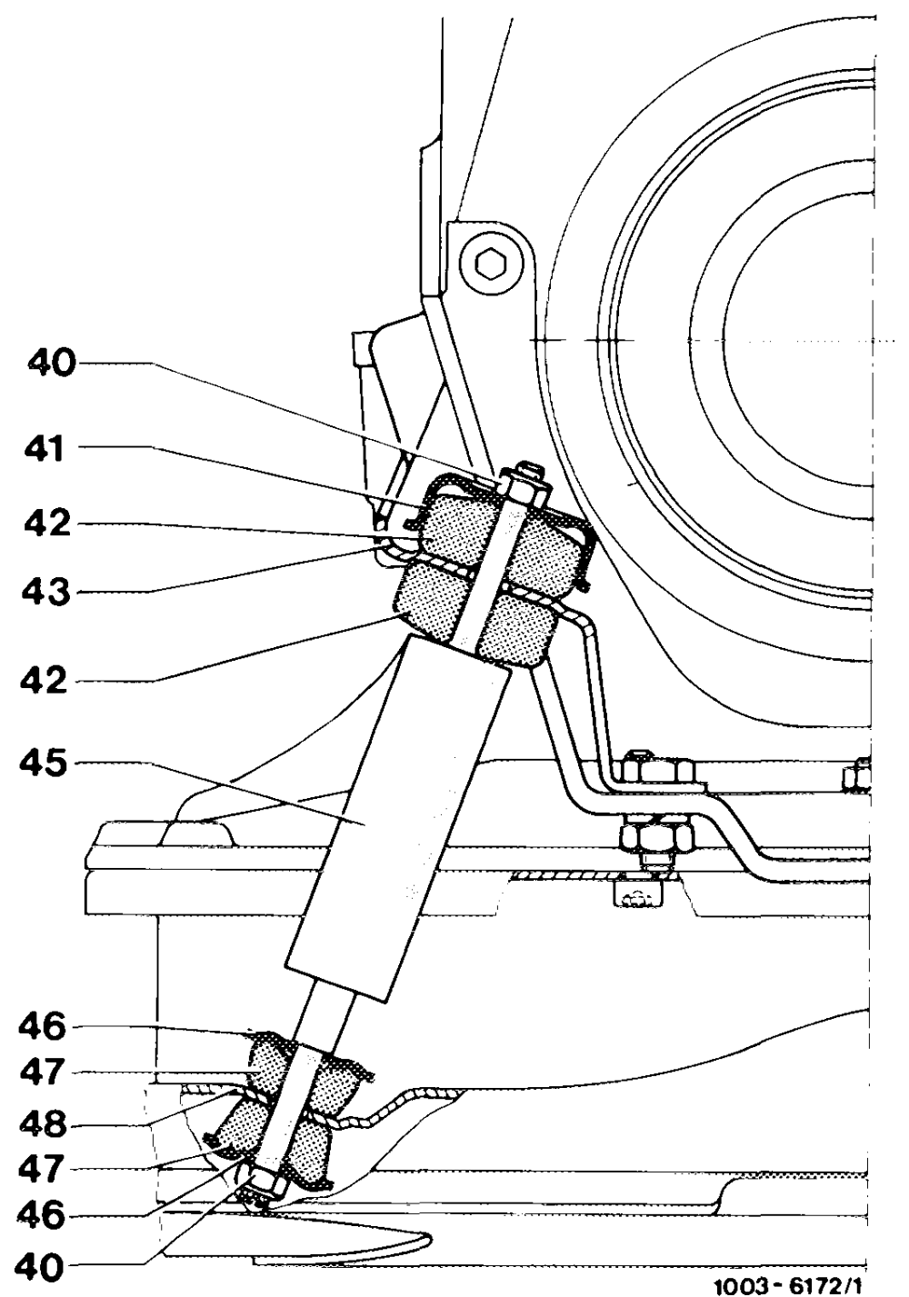
2 Compress engine shock absorber and remove in downward direction.
Installation
3 Mount lower rubber buffer (42), upper disc washer (46) and upper rubber buffer (47).
4 Compress engine shock absorber (45) and insert with piston rod in downward direction.
40 Nut 45 Engine shock absorber
41 Disc washer 46 Disc washer
42 Rubber buffer 47 Rubber buffer
43 Holder 48 Cross member
5 Mount all other parts as shown in drawing.
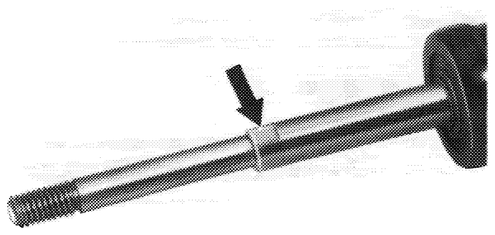
6 For tightening lower nut (40), apply counterhold to piston rod with a screwdriver at spot provided (arrow).
Model 123
Removal
1 Unscrew nut (40).
For unscrewing lower nut, apply counterhold to piston rod with a wrench at spot provided (fig. item 7).
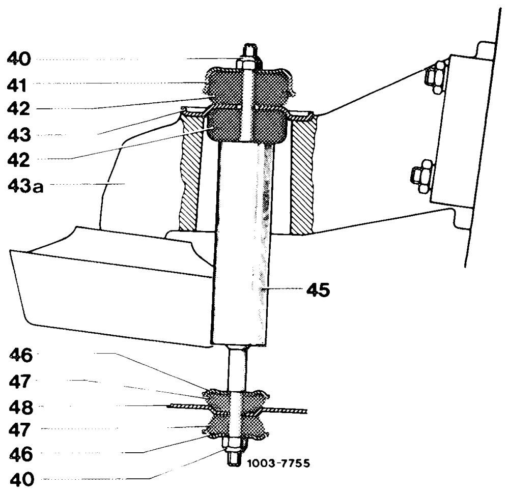
2 Unscrew flange (43) on engine carrier (43a).
3 Remove engine shock absorber (45) with flange (43a) in upward direction.
40 Nut 45 Engine shock absorber
41 Disc washer 46 Disc washer
42 Rubber buffer 47 Rubber buffer
43 Flange 48 Cross member 43a Engine carrier
Installation
4 Mount upper disc washer (46) and upper rubber buffer (47).
5 Place engine shock absorber (45) with piston rod in downward direction into bore on cross member.
6 Mount lower rubber buffer (42) and screw flange (43) to engine carrier (43a).
7 Mount all other parts as shown in drawing.
8 For tightening lower nut (1), apply counterhold with wrench to spot provided (arrow).