Replacing diaphragm for choke
WIS 07.2-136
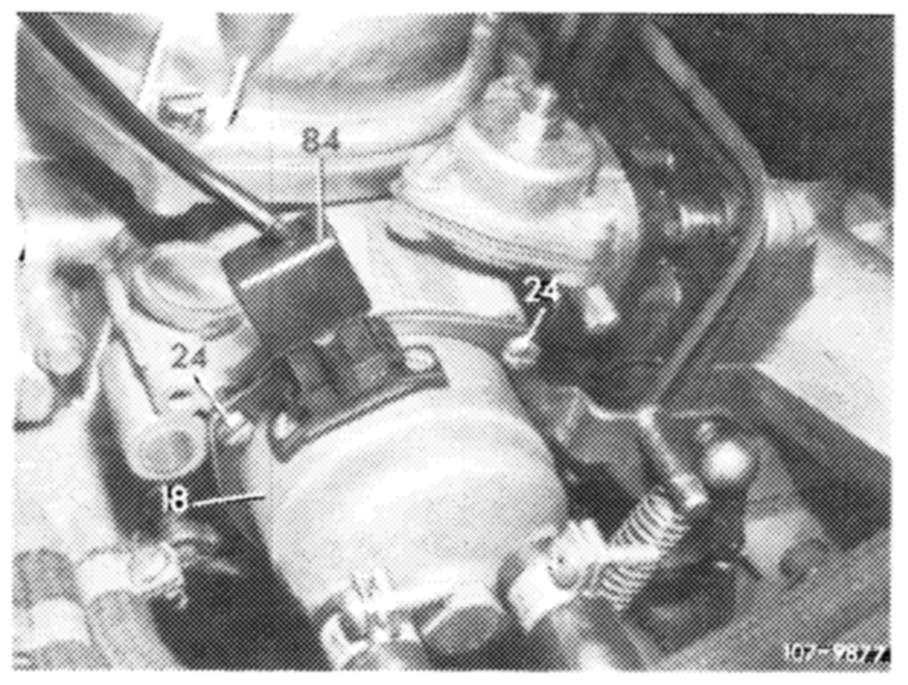
Removal and checkup
1 Remove choke housing.
For this purpose, pull off electric double plug (84) for heating choke cover and, if required, vacuum line from pulldown cover.
Unscrew fastening screws (24) and put choke cover with connected coolant hoses aside.
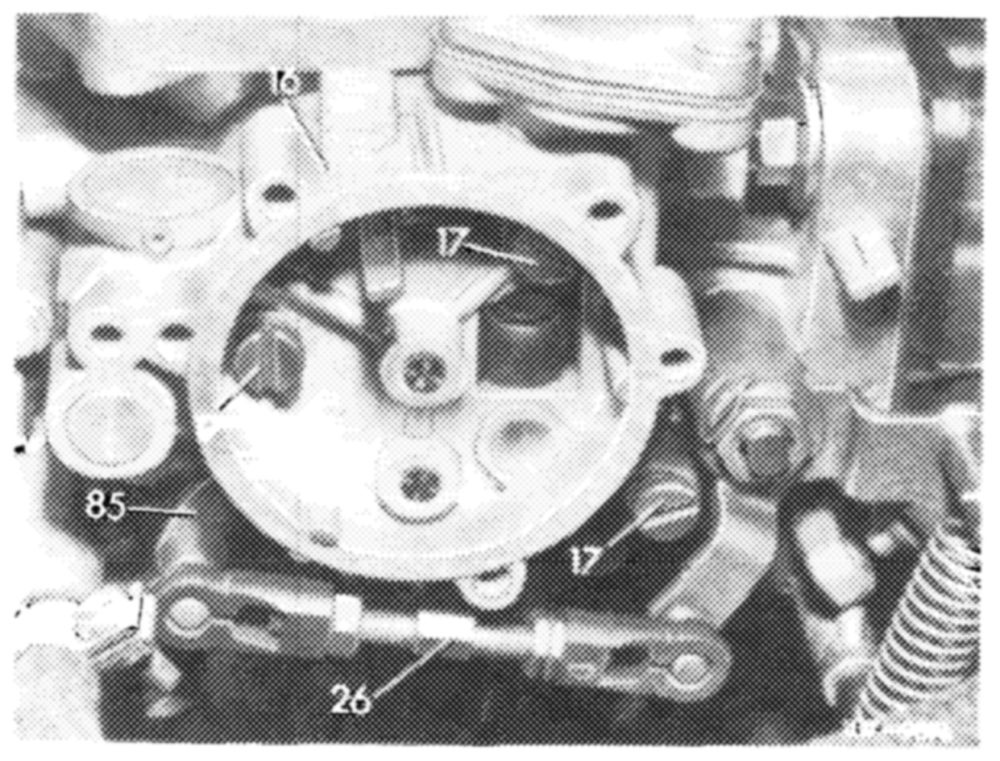
Disconnect connecting rod (26) on choke rod (85). Unscrew fillister head screws (17) and remove choke housing (16).
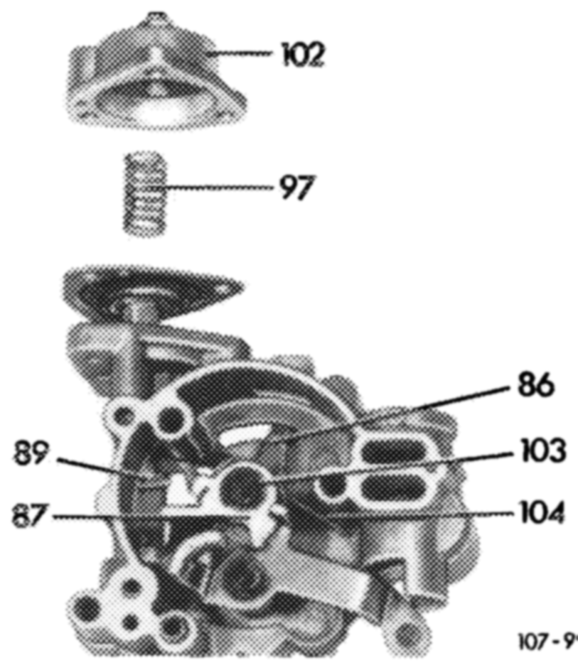
2 Remove diaphragm for choke.
For this purpose, remove cover (102) and compression spring (97).
Remove lock ( 103). Slip drive lever (86) together with fast idle cam (87) forward until diaphragm rod (89) can be pulled out with diaphragm. Check diaphragm for damage.
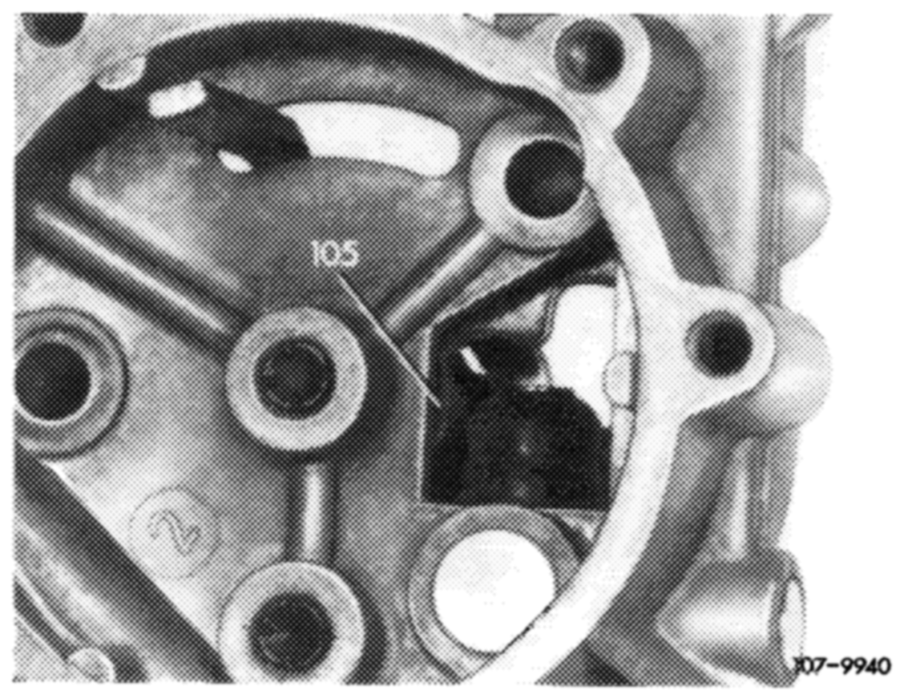
If required, install new pulldown diaphragm with diaphragm rod.
Slide fast idle cam (87) and drive lever (86) together toward the rear, while aligning spring retainer (105) with restoring spring for drive lever in such a manner that the drive lever and the fast idle cam can again return to their starting position.
Install compression spring (97) and pulldown cover (102).
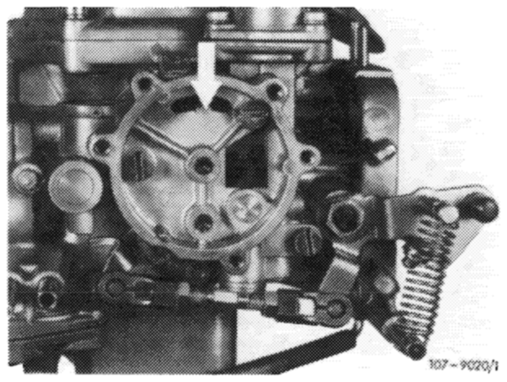
Note: !f pulldown diaphragm has been replaced, subsequently check position of fast idle cam in relation to choke rod (item 3). If the pulldown diaphragm has not been replaced, the choke housing can be installed again without this checkup.
3 Check position of fast idle cam in relation to choke rod and adjust, if required.
Check whether driver (arrow) is at right angle in relation to face of choke housing and re-bend, if required.
Pulldown position
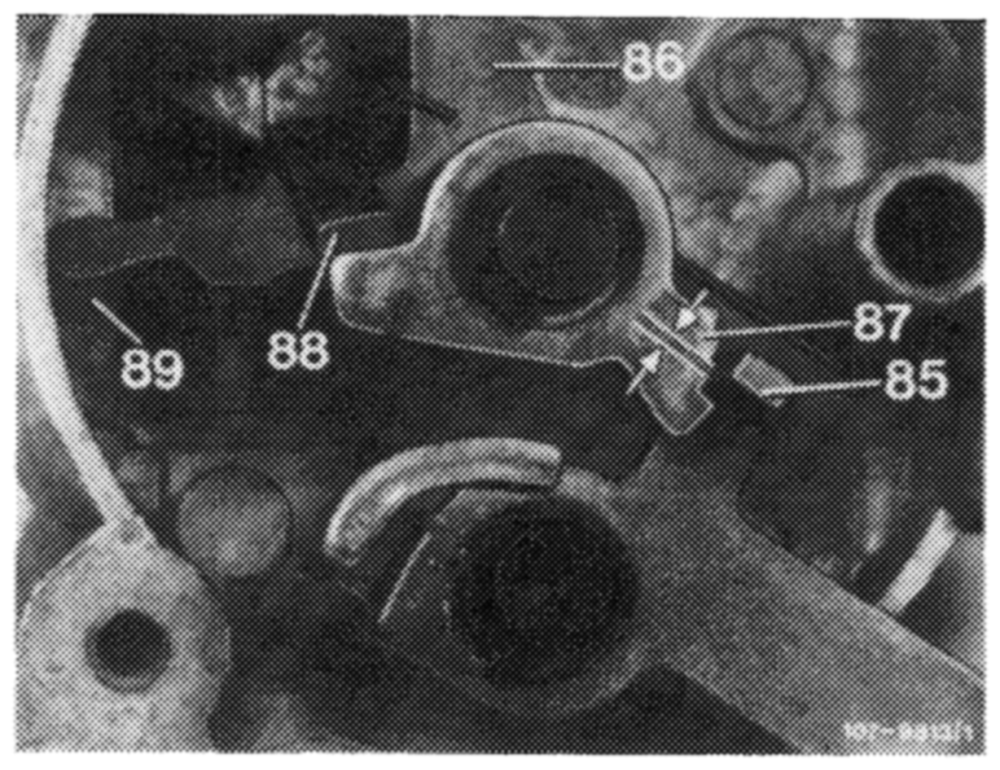
Push diaphragm rod (89) upwards up to stop and drive lever (86) to the left (drive lever should rest against diaphragm rod). Choke rod (85) should rest approx. in center (arrows) of second-highest detent (pulldown position) of fast idle cam (87). Bend driver (88) accordingly, if required.
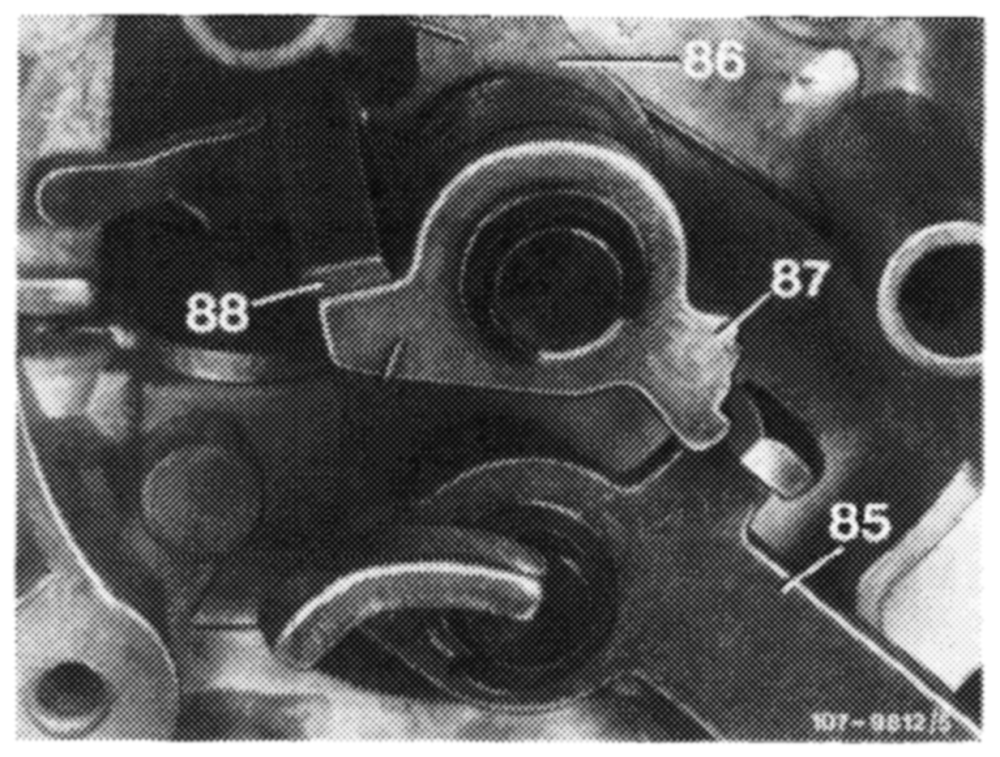
Full start position
Push drive lever (86) against stop to the left (choke slide valve completely pushed in). In this position, the choke rod (85) should rest on highest detent of fast idle cam (87) for a length of min. 0.5 mm. Bend driver (88) accordingly, if required.
Note: If driver (88) is bent as required, check pulldown position once again.
Idle speed position
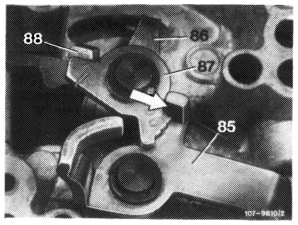
Push drive lever (86) completely to the right against stop and choke rod (85) completely up. Choke rod should move into idle speed position (arrow) and should not rest on detent segment of fast idle cam (87). Refinish detent segment accordingly, if required.
Installation
4 Install choke housing and choke cover vice versa to item 1. Use new seals.
Attention! Do not forget insulating gasket between choke cover and choke housing.
5 Adjust choke (07.2~—125).