Replacing valve guides
WIS 05-2850
Preceding work: Vatve guides inspected (05-2845).
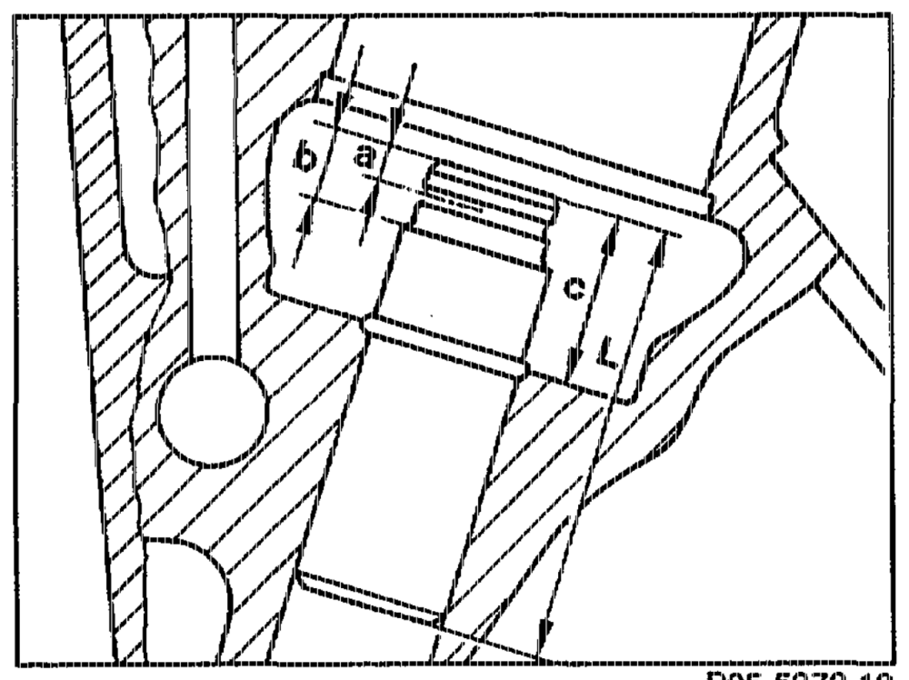
A. Non-ferrous metal vaive guides, engine 104.980/981 (ist and 2nd version) and engine 104.990 (1st version)
P05-5372–13
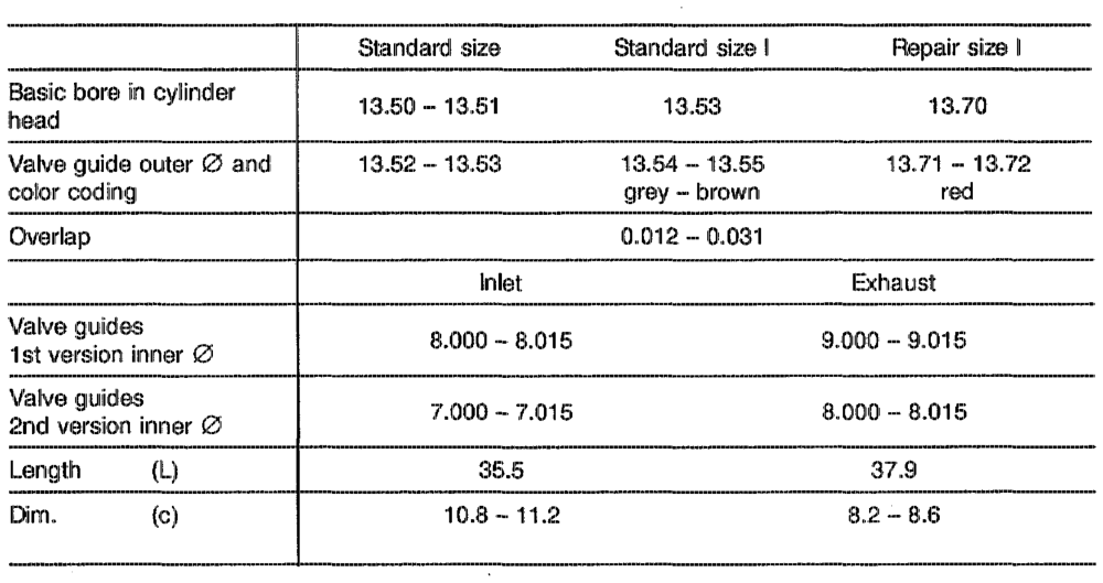
Valve guides and basic bores
aphhin §=RA, 05.1225-2850/1
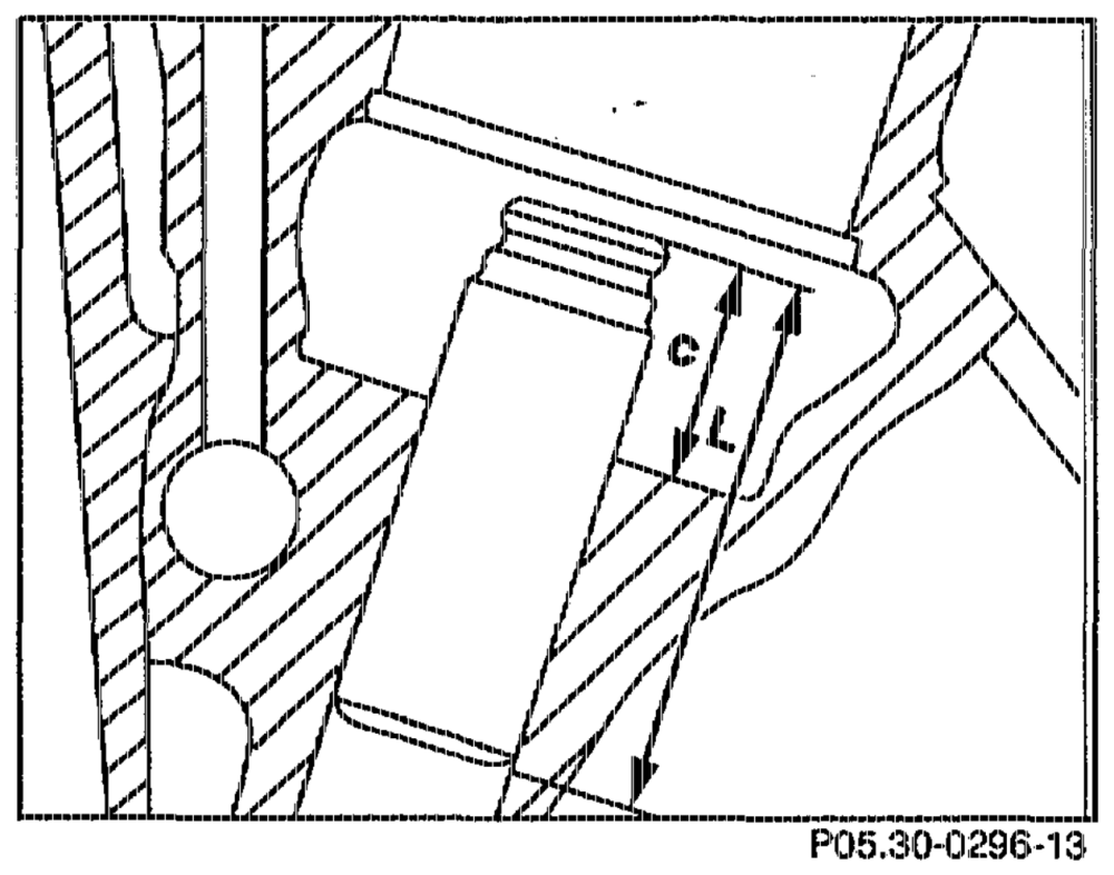
B. Sintered metal valve guides engine 104.980/981 (3rd version) engine 104.990 (2nd version) engines 104.940/941/942/943/944/945/ 992/994/995/996 as of start of production
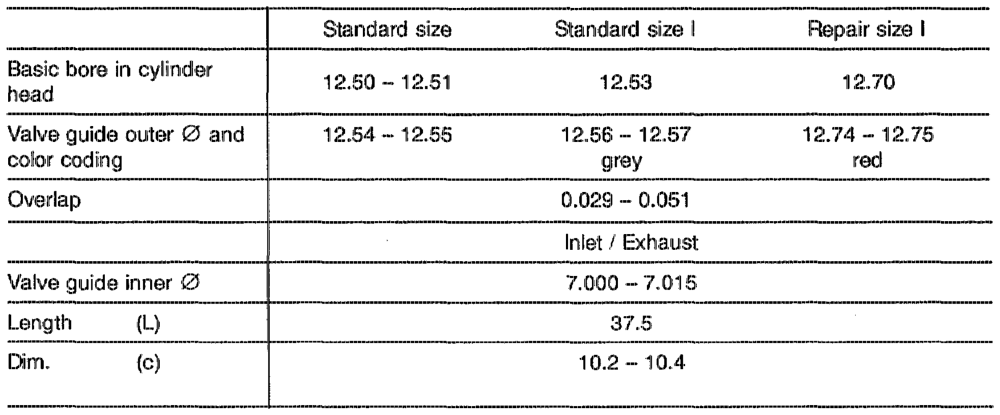
Valve guides and basic bores
sohihie RA 05, 1225-2850/2
Replacing non-ferrous metal and sintered metal valve guides
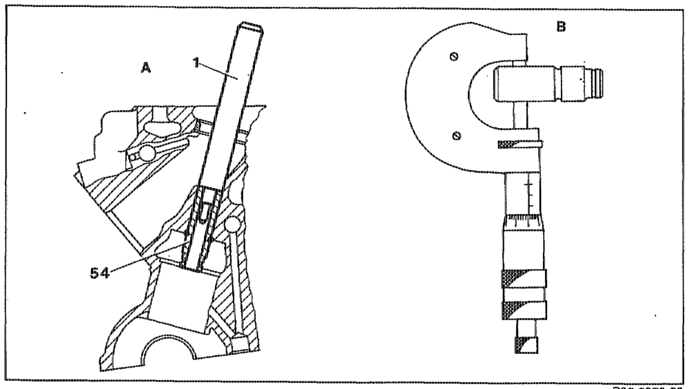
Knocking out valve guide
P05-5373–55
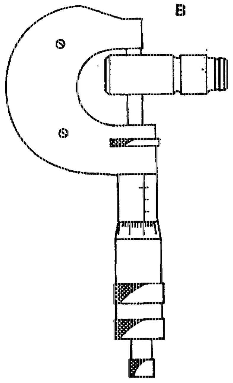
A Knocking out valve guide B Measuring valve guide outer @
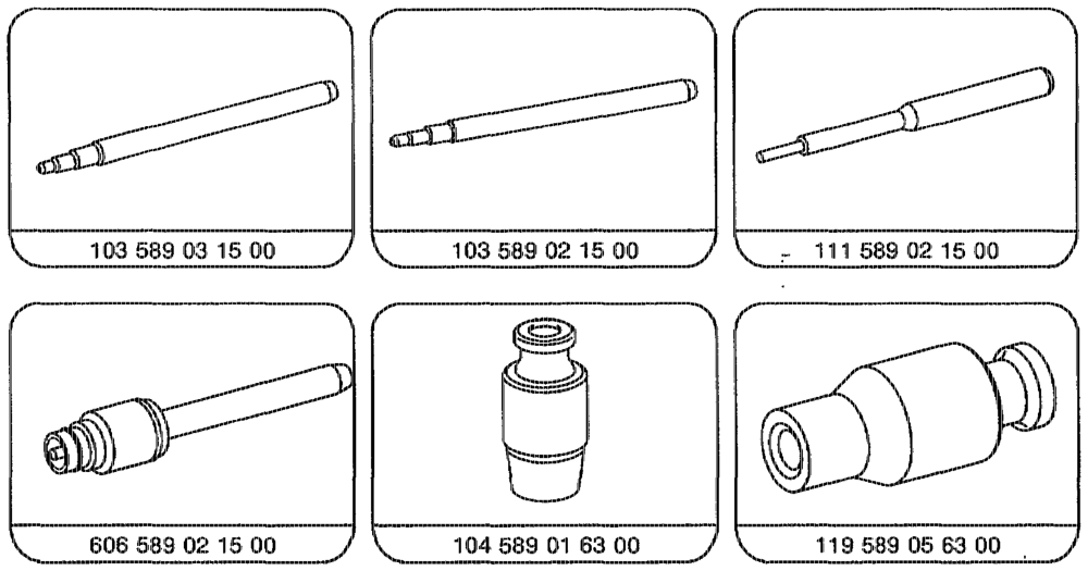
Valve guide (54) 2.0… ee eee ee eee see knock out with drift (1) frorn the combustion chamber side. Drift 111 589 02 15 00 for valve guide inner 3 7 mm. Drift 103 589 03 15 for valve guide inner @ 8 mm. Drift 103 589 02 15 for valve guide inner @ 9 mrn. Measuring valve guide Outer …….0, see eee ee see eee measure with micrometer. Determine which valve guide was installed; match up next larger valve guide, see table. Basic bore in cylinder head ream standard size or broach repair size according to matched valve guide.
athe RA 05.1225-2850/3
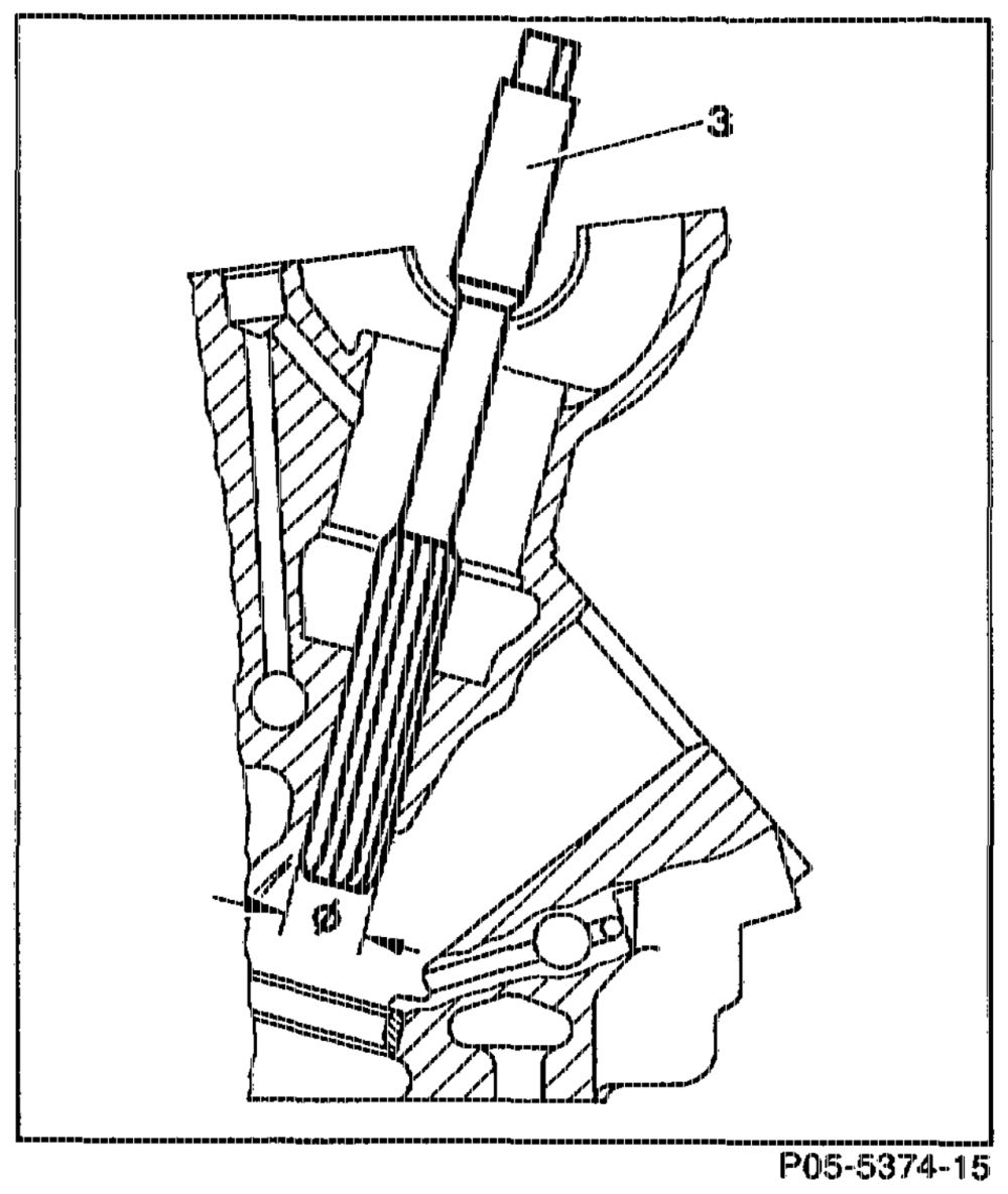
Standard size (reaming basic bore with rearner)
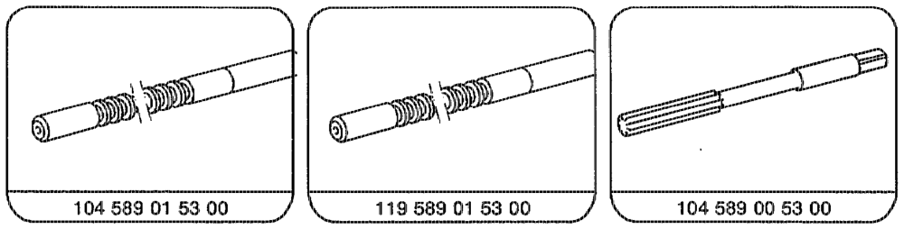
ream through with reamer (3). Use reamer 104 589 00 53 00 for basic bore @ 13.53 mm Use reamer 119 589 00 53 00 for basic bore @ 12.53 mrn
Note Lubricat with petrol when reaming. Apply only slight pressure and do not tilt rearner (3). Clean blades of reamer before each reaming operation.
oti = RA 05.1225-2850/4
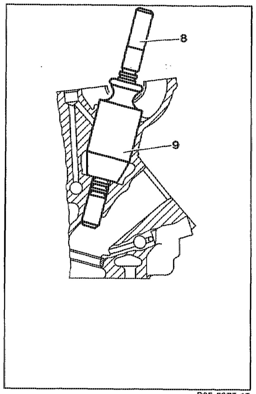
Repair size (broaching basic bore with breaching tool)
POS-5375–15
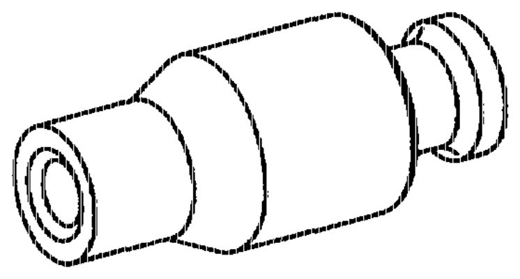
Guide sleeve (9) and broaching tool (8) insert into bucket tappet basic bore. Use guide sleeve 104 589 01 63 00 and broaching tool 104 589 01 53 00 for basic bore @ 13.7 mm. Use guide sleeve 119 589 05 63 00 and broaching tool 119 589 01 53 00 for basic bore @ 12.7 mm. Broaching tool (8) press through.
Note Lubricate with petroleurn when broaching. Clean broaching tool (8) with compressed air before and after each broaching operation.
sgn RA 05.1225~2850/5
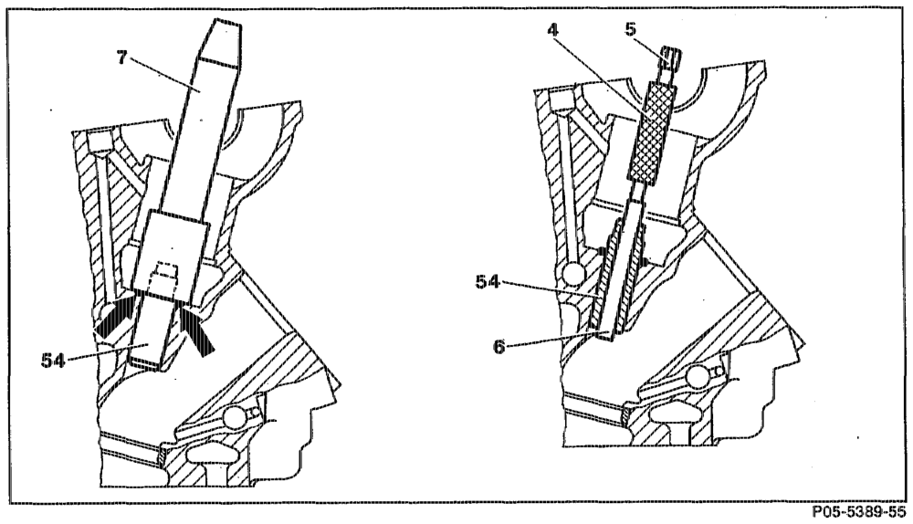
inserting valve guide
supercool valve guides (54) in liquid nitrogen (for about 3 minutes). If no liquid nitrogen available, heat cylinder head in water bath to about 80 °C. moisten valve guide (64) on outside with oil.
Note It is not necessary to heat the cylinder head or to cool the valve guides (54). knock in as far as the stop (arrows) with drift (7). Insertion drift 119 589 02 15 00 inlet © 7 rm for basic bore 13.5 and 13.7.
Insertion drift 606 589 02 15 00 inlet/exhaust 2 7 mm for basic bore 12.5 and 12.7.
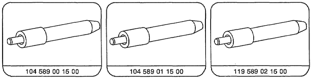
Insertion drift 104 589 00 15 00 inlet @ 8 mm.
RA 05.1225-2850/6
Insertion drift 104 589 02 15 00 exhaust @ 8mm.
Insertion drift 104 589 01 15 00 exhaust @ 9 mm.
Note The circlip is not fitted to the sintered metal valve guides. The insertion depth is determined by the insertion drift.
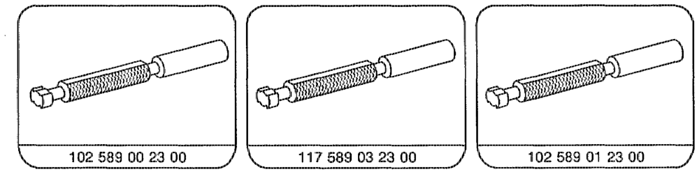
inspect that it is tight once cylinder head is Valve guide (64) ………005 see eee ae cooled down. inspect with gauging drift (4). Inner @ of valve guide (54) Gauge 102 589 00 23 00 inlet @ 8 mm. Gauge 117 589 03 23 00 exhaust 2 9 mm. Gauge 102 589 01 23 00 inlet @ 7 mm.
Note It must be possible to fully insert the GO side (6) of the gauge (4).
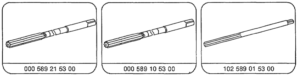
Non-ferrous metal valve guides: ream inner @ with reamer, if necessary. Reamer 000 589 21 53 00 inlet @ 8 mm. Reamer 000 589 10 53 00 exhaust @ 9 mm. Reamer 102 589 01 53 00 inlet, exhaust @ 7 mrn.
Sintered metal valve guides: if the gauge cannot be inserted, the valve guide should be replaced as the material of the sintered metal guides too hard for reaming.
cotta
RA 05.1225-2850/7
agtie RA 05,1225-~2850/8
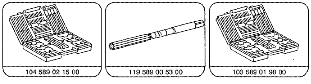
e.g. Hunger D-8000 Munich 70 Order no. 221.60.000
atti = RA 05.1225-2850/9