Function description of crankcase ventilation
WIS 01-0400
Engine 104.98 CFI-Jetronic
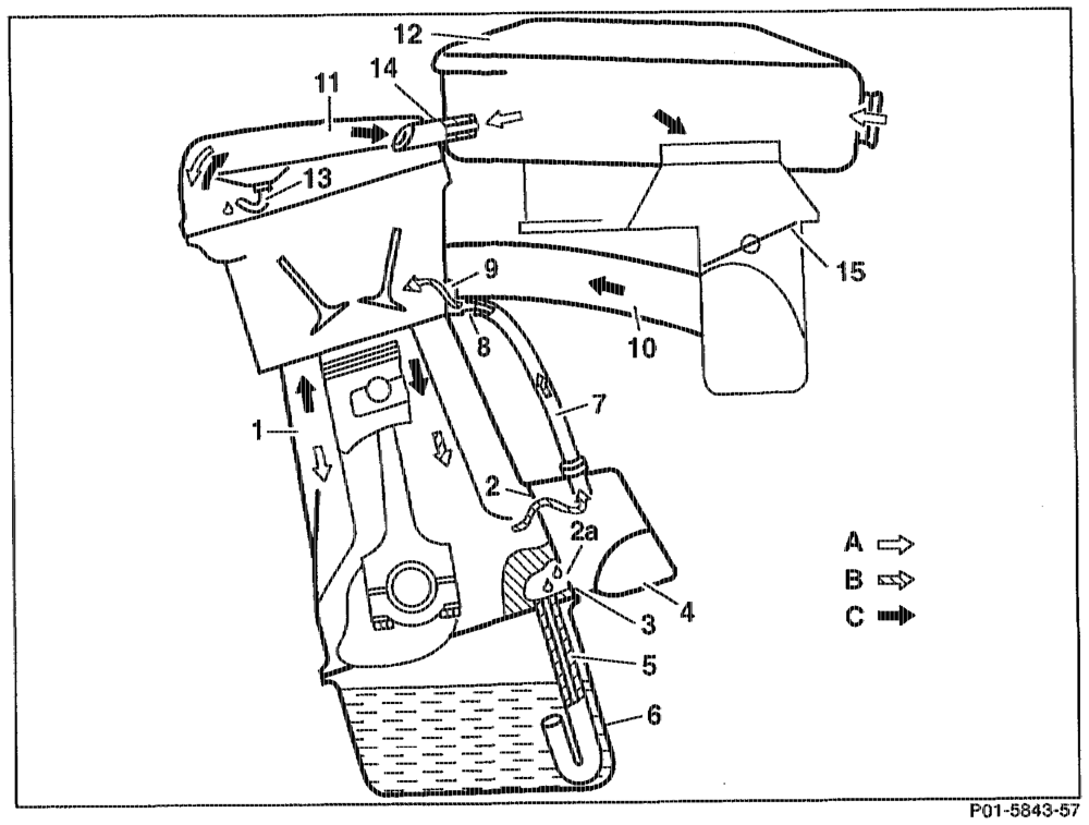
1 Crankcase 10 Intake manifold
2 Air admission opening in crankcase W Cylinder head cover 2a Opening for oil outlet 12 Air cleaner
3 Gasket 13 Oil separator
4 Combination support {air admission housing) 14 Air admission or vent hose
5 Oil outlet pipe 15 Throttle vaive
6 Oil sump A Fresh air
7 Air admission pipe B Part load blow-by gases
8 Restriction drilling, 2 mm dia. Cc Full load blow-by gases
9 idle speed air port
Function at idle speed position and mic-
load
(Throttle valve (15) closed or only slightly open, Entrained engine oil is separated out in the high intake manifold vacuum) combination support (4) and passed along an oil outlet pipe (5) to the oil sump (6). The crankcase (1) is vented in part load via the The vacuum which is thus produced in the combination support (4) through a 2 mm dia. crankcase draws in fresh air from the air restriction drilling (8) in the intake manifold (10) cleaner (12) through the air admission or vent to the idle speed air port (9). hose (14). The addition of fresh air is an additional measure to prevent the formation of sludge in the engine oil.
whe §=RA 01.1214-0400/1
Function at upper part load to full load Throttle valve (15) open:
At full load the entire ventilation quantity is passed through the oil separator (13) in the cylinder head cover (11), the air admission and vent hose (14), the air cleaner (12) the intake manifold (10) to the cornbustion chambers.
Engine 104.990 LH-SFi-Jetronic
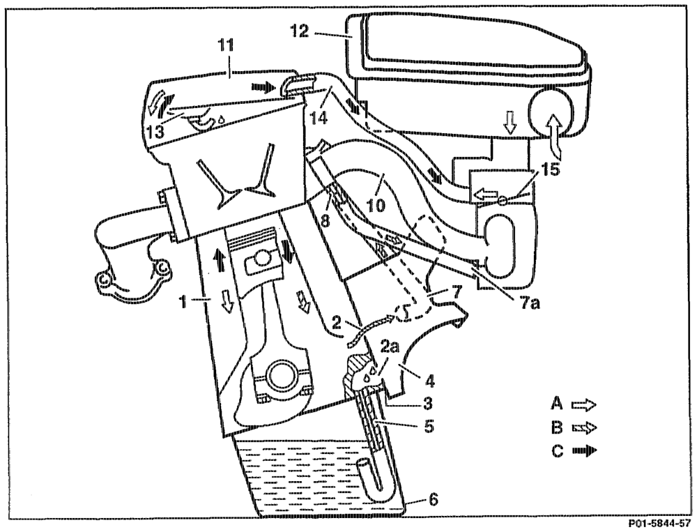
Intake manifold
1 Crankcase
2 Air admission opening in crankcase Cylinder head cover 2a Opening for oil outlet Air cleaner Oil separator
4 Gasket Air admission and vent hose
4 Combination support (air admission housing) Throttle valve
5 Oil outlet pipe Fresh air
6 Oil sump Part load blow-by gases
7 Air admission pipe Full load blow-by gases 7a Air admission pipe
8 Restriction drilling 2 mm dia.
9 idle speed air port
cotiy §=RA 01.1214-0400/2
Function at idle speed position and midFunction at top part load up to full load
load
Throttle valve (15) open: (Throttle valve (15) closed or only slightly open, At full load the entire ventilation quantity is high intake manifold vacuurn) passed through the oil separator (13) in the cylinder head cover (11), the air admission and The crankcase (1) is vented in part load via the combination support (4) of the vent pipe (7) vent hose (14), the air cleaner (12), the intake through a 2 mm dia. restriction drilling (8) in the manifold (10) to the combustion chambers. intake manifold of the vent pipe (7a) to the intake manifold (10). The vacuum thus produced in the crankcase Entrained engine oil is separated out in the draws in fresh air from the air cleaner (12) along combination support (4) and passed along an oil the air admission and vent hose (14). The addition of fresh air is an additional outlet pipe (5) into the oil sump (6). measure to prevent the formation of sludge in the engine oil.
oti = RA 01.1214-0400/3
Engine 104.941/942/943/944/945/99 1/992/994/995/996 with HFM sequential
multiport fuel injectlon/ignition system (HFM-SF’
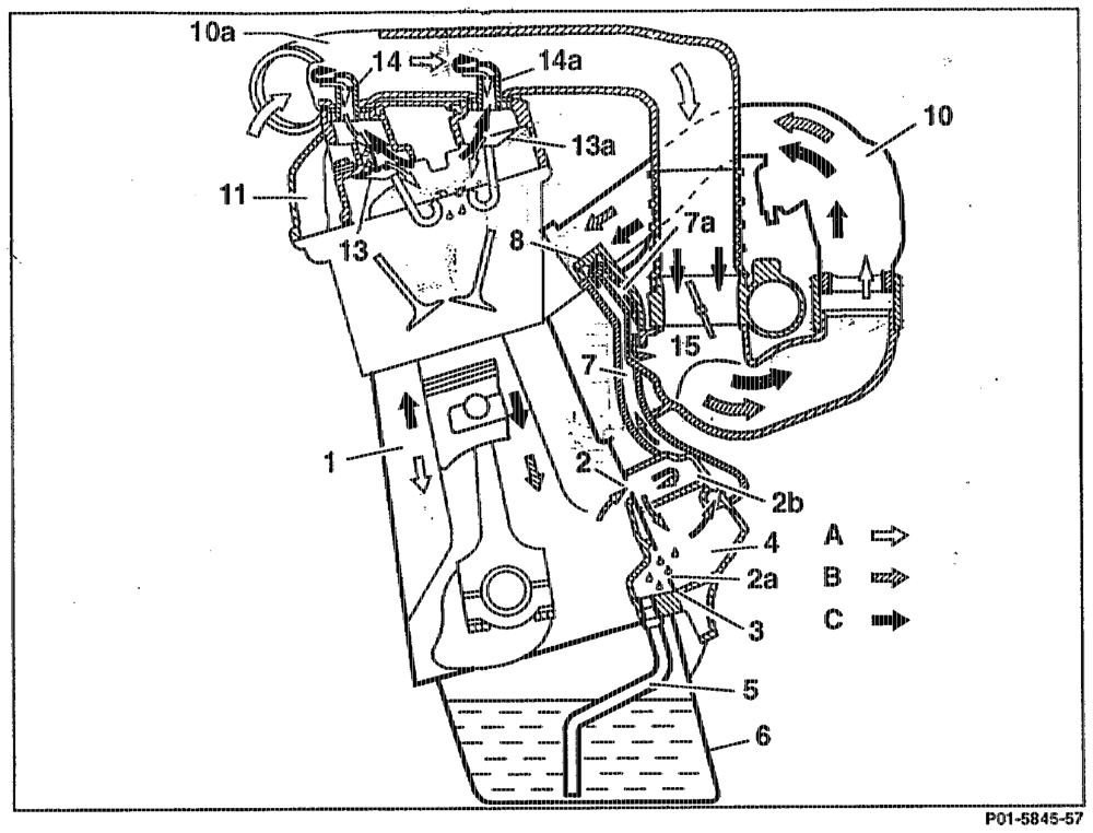
1 Crankcase 10 Intake manifold
2 Air admission opening in crankcase 10a Intake air pipe 2a Opening for oil outlet WW Cylinder head cover 2b Filter 13 Oil separator with syphon
3 Gasket 13a Oil separator with syphon
4 Combination support (air admission housing) 14 Air admission and vent hose @ 9 mm
5 Oil outlet pipe 14a Air admission and vent hose @ 7 mm
6 Oil sump 15 Throttle valve
7 Air admission pipe A Fresh air 7a Vent pipe B Part load blow-by gases
8 Restriction crilling 2 mm dia. Cc Full ioad blow-by gases
Function at idle speed position and mid-
load
(Throttle valve (15) closed or only slightly open, Entrained engine oil is separated out in the combination support (4) and passed along the high intake manifold vacuum) oil outlet pipe (5) into the oil sump (6). The crankcase (1) is vented in part load through the combination support (4) with filter (2b) of The vacuurn which is thus produced in the the vent pipe (7) through a 2 mm dia. restriction crankcase draws in fresh air frorn the intake air drilling (8) in the manifold of the vent pipe (7a) line (10a) through the air admission and vent to the intake manifold (10). connections (14) and (14a).
odin RA 01.1214–04.00/4
The addition of fresh air is an additional measure to prevent the formation of sludge in the engine oil. The vent connections (14) and (14a) have a scoop adapted to the pressure fluctuations in the intake air line (10a).
Function at top part load up to full load Throttle valve (15) open:
At full load the entire ventilation quantity is passed through the oil separators (13) and (13a) in the cylinder head cover (11) to the air admission and vent connections (14) with @ 9mm reduction and (14a) with @ 7 mm reduction of the intake air line (10a), to the intake manifold (10) to the combustion charnbers.
othe = RA 01.1214-0400/5