Femoving and installing engine
WIS 01-0300
Preceding work: Operation no. of operation texts and work units or standard texts Warming instructions when hod open (01-0085) and flat rates: Bottom engine compartment panel removed (Maint. Manual) 01-2400, 2800 Air cleaner removed (AR09.10–1050D) Radiator removed (20-4200) Viscous fan coupling removed (20-3120)
A. Models 124, 129, 140
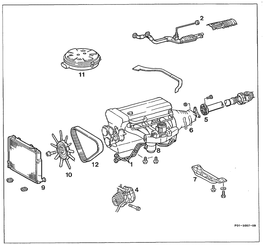
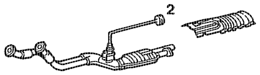
see eee ee eee remove, install. Engine with transmission cee eee cee eee disconnect, connect, encode radio, model 140 Ground cable at battery normalize power windows.
anh = RA 01.1215-0300/1
Coolant 2… ee ee ee eee tee drain at crankcase. If AC fitted ….. See eee eee eee attach guard plate to condenser. Air-to-oil cooler pipes (1) at air-to-oil cooler disconnect, connect (step 3). HAC fitted: oe ee eee ee take off poly V-belt, fit on (13-3200). extract oil from reservoir, adjust oil Ito correct level (step 5). remove with piping connected, place to the side, fit on. Oil pipes of power steering pump, automatic traNSMISSION 2… Le ee ee ee take off, seal and fit on (steps 7–8). Fuel pipes… ee eee ee ee eee take off, seal, open fuel filler cap briefly first of all, fit on (step 9). Bowden cable (accelerator control) ……… take off, fit on (30-1010, step 10). Heating water return pipe 6… ee eee detach, attach. Component compartment cover ………65 remove, install model 140 (step 14). Right cable duct ………..005 Lecce nee remove, install model 140 (step 14). Electrical connections ………..66. see disconnect, connect (steps 15 to 21). Electrical connections, starter disconnect, connect (steps 23, 24). Vacuum pipes for brake pressure regulator ete. detach, attach. Exhaust system …….. snc eens . remove, install (49-0045, 49-0170). Flexible disc (5) of transmission (6) …….. detach, attach, replace self-locking nuts (step 25). Clamping nut and intermediate bearing fixture slacken, tighten (steps 26, 27). Shift rods at tansmission ………..00. . detach, attach (step 28). unbolt hydraulic pipes for clutch, bolt on If manual transmission fitted: …………. (step 29). if automatic transmission fitted: ……….. disconnect starter lockoutswitch, transmission overload protection,electric wiring, connect (steps 30, 32, 33, 34). Engine hoist 2.6… 0.0… eee eee senses attach to lifting lugs, detach (step 35). Transmission ………. see se eee wee support. remove, install (step 37). Rear engine support (7) without engine mounts Exhaust bracket at transmission ……….. unbolt, bolt on (step 38). Front engine mounts (8), left and right …… unbolt from below, bolt on (step 39). Guard plate at component cornpartment wall insert, take off. Engine ……….. wee eee wet e eens raise with engine hoist, lower (step 41). Front and rear engine mounts ………… examine. Coolant, oil and fuel hoses ………..0.. examine. If automatic transmission fitted ………… adjust Bowden cable for control pressure (27-100).
atte = RA 01.1215-0300/2
Oil drain plugs… 0… eee ee check tightening torque. Oil level in engine and transmission …….. adjust to correct level (18-0020). Coolant ……….. vee eee e ewes pour in, check anticorrosion/antifreeze agent and adjust to correct ratio (20-0100). Idle speed oo… eee eee scenes check, adjust (07-2056). Fault memory 02.0.0… eee eee ee ee eee read, erase (step 52).
Note Faults stored in the fault memories must be rectified after completing the work and erased.

See Diagnosis Manual Volume 2: Index 0: Connecting and using test equipment. Leak tightness …. see eee e wenn ane check after test run of engine.
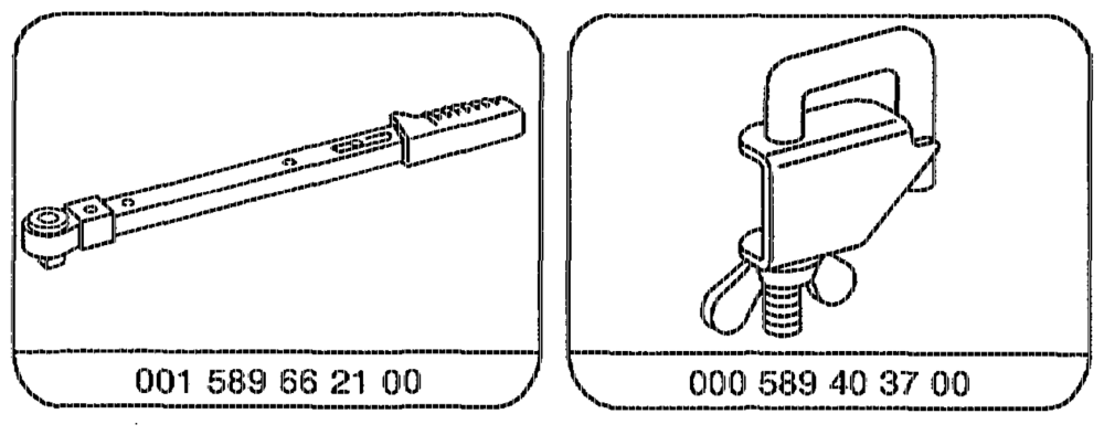
Special tools
oti §=RA 01.1215-0300/3
Removal device components model 3188 e.g. Wilbar GmbH & Co KG (lifting capacity 500 kg) Herder Str. 42895 Remscheid
Shop-made tools

Note a In the case of engine darnage involving damage to the pistons, valves etc., parts may have got in as far as the catalytic converter, or pre-catalytic converter. When raplacing the engine, it is essential to remove such parts otherwise they will be pulsed back into the cylinders as a result of the gas vibrations in the exhaust system and may once again cause engine damage. In addition, these parts may cause mechanical damage to the catalytic converter. It is therefore essential to remove any foreign bodies in the exhaust system in the case of such engine damage. Catalytic converters which have been damaged must be replaced.
Engine 104.990 in model 140
When replacing the crankcase or installing a raconditioned engine, the matched ignition control module (Dl) should be used, see (01-1000).
othe =RA 01.1215-0300/4
Removing and installing engine with transmission.
1 Disconnect ground cable at battery.
Installation note Encode radio, model 140 normalize power windows.
2 If AC fitted: attach guard plate to condenser of AC system.
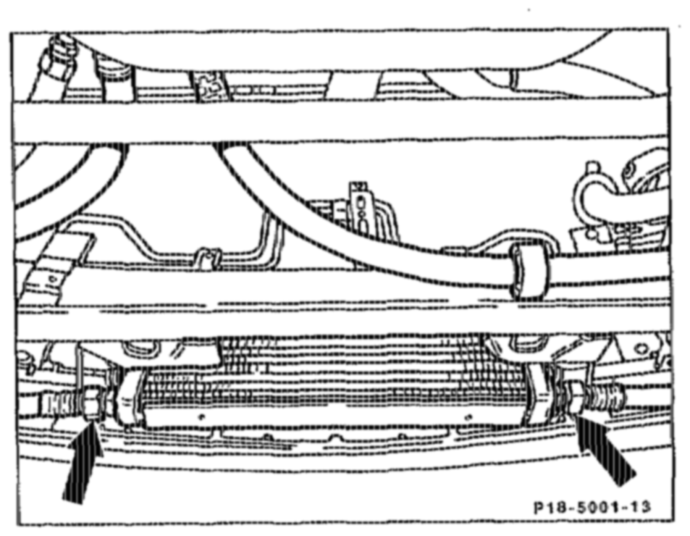
3 Unbolt air-to-oil cooler pipes at air-to-oil
4 elt ai or pipes at air-to-o}
cooler (arrows)
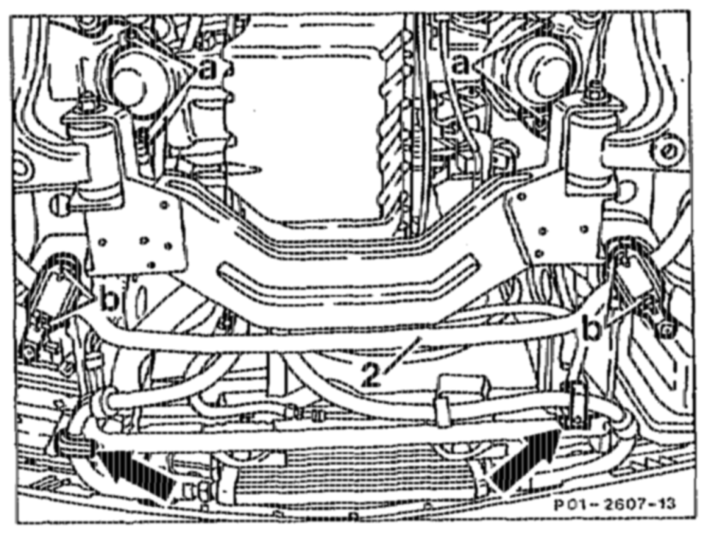
Model 140
Model 140 @ Unbolt oil cooler pipes at body (arrows).
4 If AC fitted: ramove poly V-belt (13-3420).
Model 140
whe RA O1.1215-0300/5
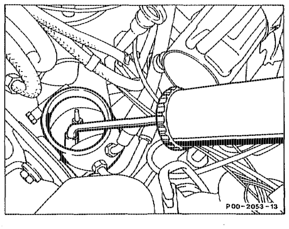
5 Extract oil from the reservoir of the power steering pump with the priming pump for extracting oil.
Installation note Check fluid level of power steering system. Fill up power steering with the specified fluid. Top up fluid to the marking with the engine running. Turn steering several times from full left to full right lock. When fluid is at normal operating temperature, it must extend to about 20 mm below the edge of the reservoir; when fluid is cold to 6–8 mm below the marking.
6 Detach AC compressor of air conditioning system from the engine. Unscrew bolts (35) and nuts (for attaching pipe assy); attach AC compressor to the side at the bottom of the engine compartment with the pipes connected.
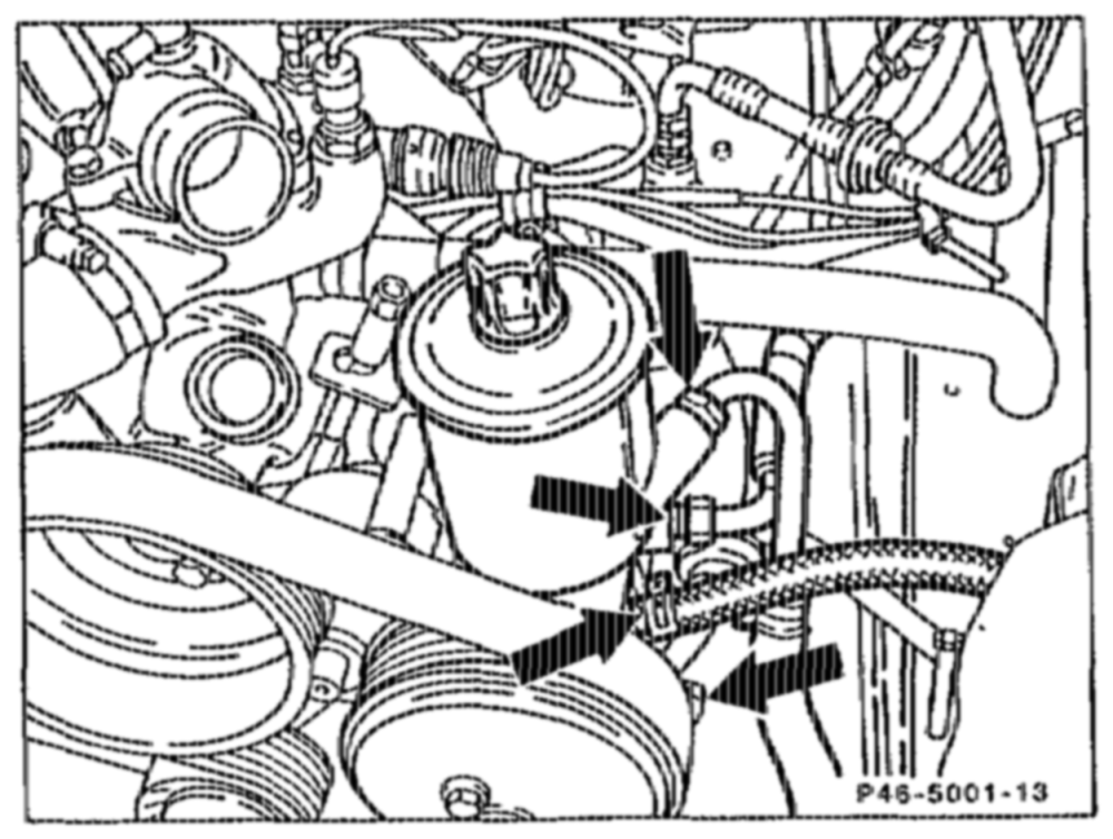
7 Unbolt suction and pressure oil pipes at power steering pump and tandem high pressure pump, respectively (arrows).
Installation note for tandem pump Bleed pressure oil pump (level section) of tandem pump (32-6300).
atin §=RA01,1215-0300/6
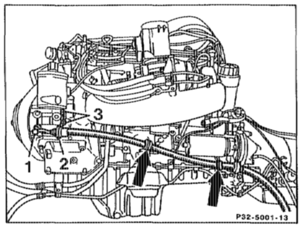
8 Unbolt delivery pipe of level pump (1), unscrew M8 bolts (3) of metal bracket (2) and press pressure pipe out of the metal brackets (arrows).
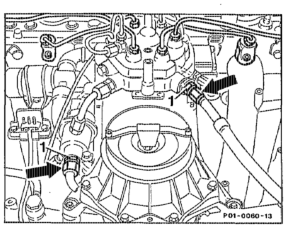
Modal 140
9 Briefly open filler cap in the fuel tank to release the pressure. Unbolt fuel pipes (arrow) and seal with spacial tool 000 589 40 37 00. Counter-hald the connection fitting (1) when slackening the fuel pipe.
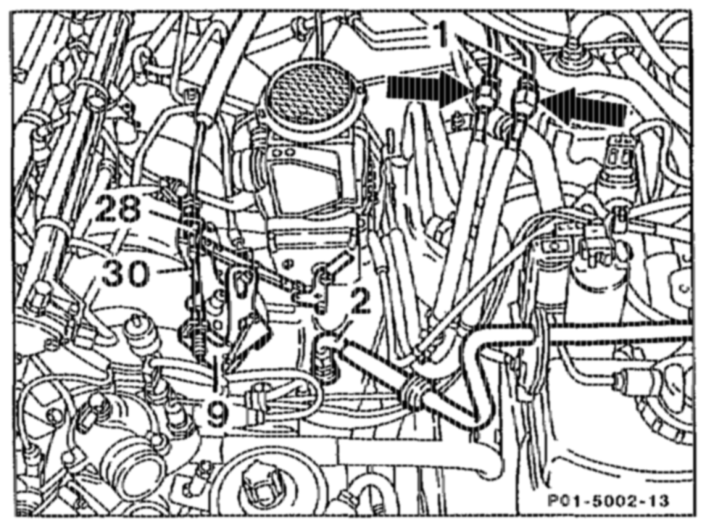
Engine 104.98, models 124, 129
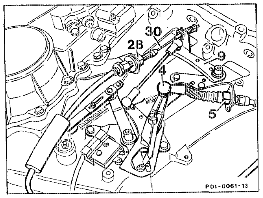
Engine 104.99
10 Detach Bowden cable (30) from accelerator control lever (9). Compress plastic clip (28) and pull out Bowden cable.
Installation note Adjusting Bowden cable (30-1010).
Engine 104.98
ge RA 01.1215-0300/7
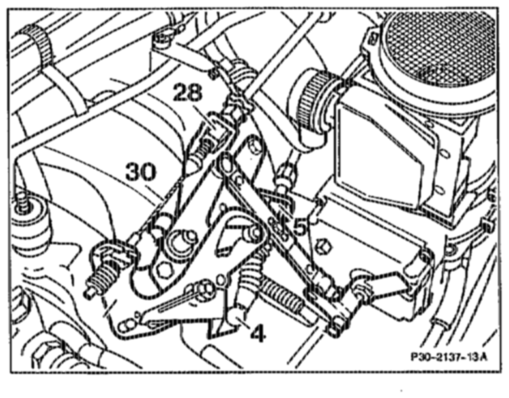
control lever (9). Compress plastic clip (28) and pull out Bowden cable.
Installation note Adjusting Bowden cable (30-300).
Engine 104.99
12 Detach heater hoses and vacuum pipes in the engine cornpartment. If automatic transmission fitted, pull off vacuum pipe at 2-way valve.
Models 124, 129
13 Detach connector from the oil level gauge and frorn the oil pressure sensor. Slacken all cable straps of the engine wiring harmess. Detach all connectors along the engine wiring harness. Remove engine wiring harness
Mocel 140
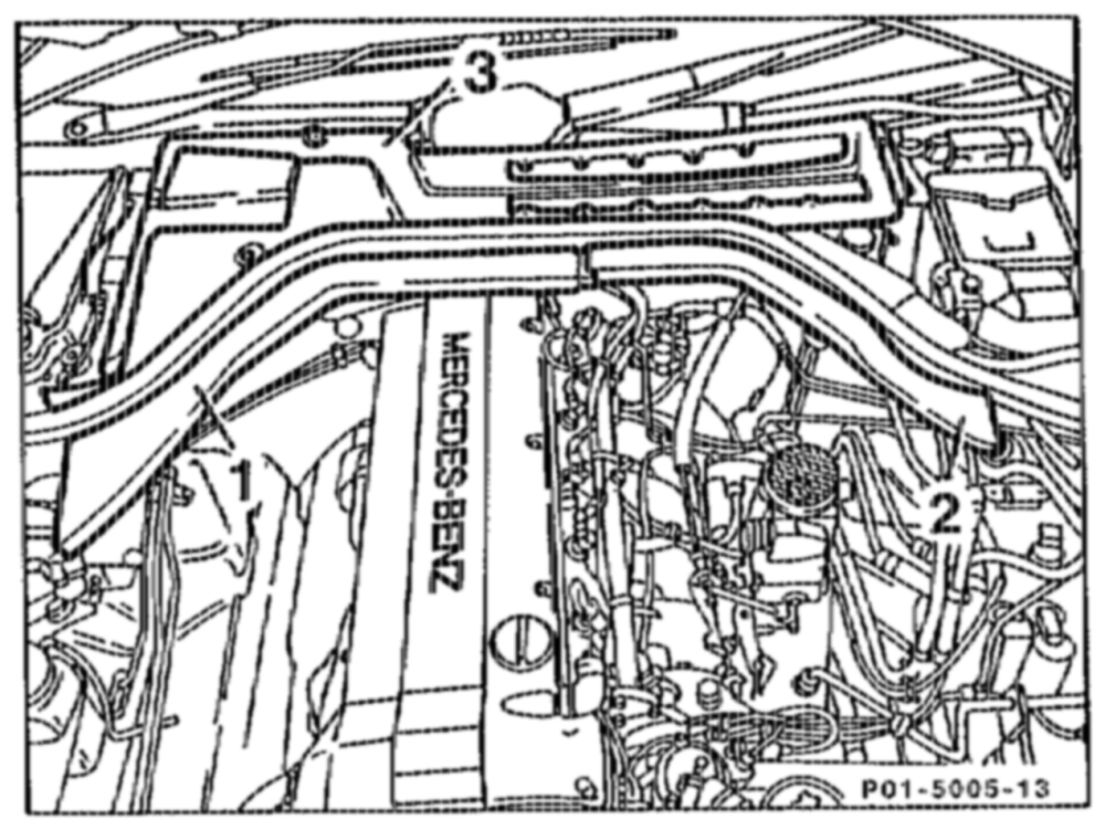
14 Rernove component compartment cover (3), open cable duct (1) and remove right-hand side.
Model 14.0
athe =RA 01,1215-0300/8
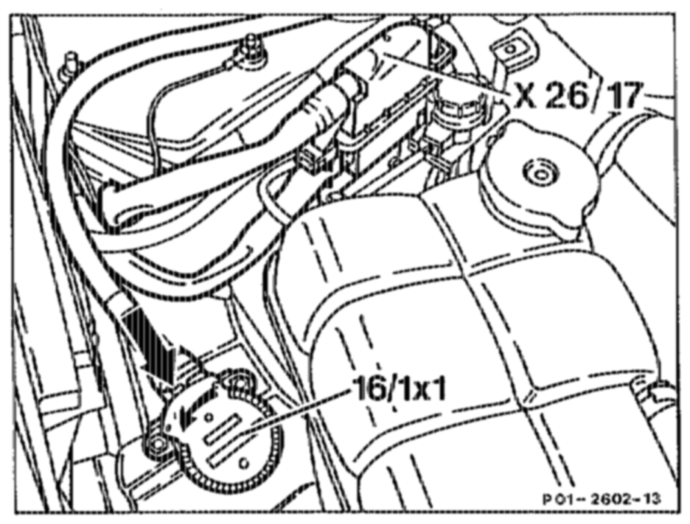
M16/1×1) of the engine wiring harnesses. Press ratchet (arrow) and turn to release the connector (16/1×1).
16 Place engine wiring harnesses on the engine.
Model 140
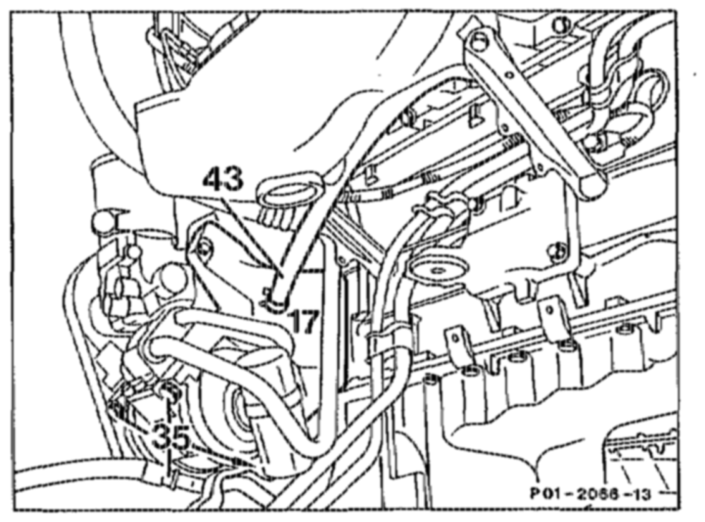
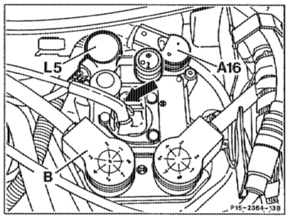
17 At the ignition control module, unplug crankshaft position sensor connector (L5), LH control module connector (B), knock sensors connector (A16) and detach vacuum pipe (arrow).
18 Detach suction pipe of the evaporative emission control system from the connector on the left-hand wheelhouse.
Model 124
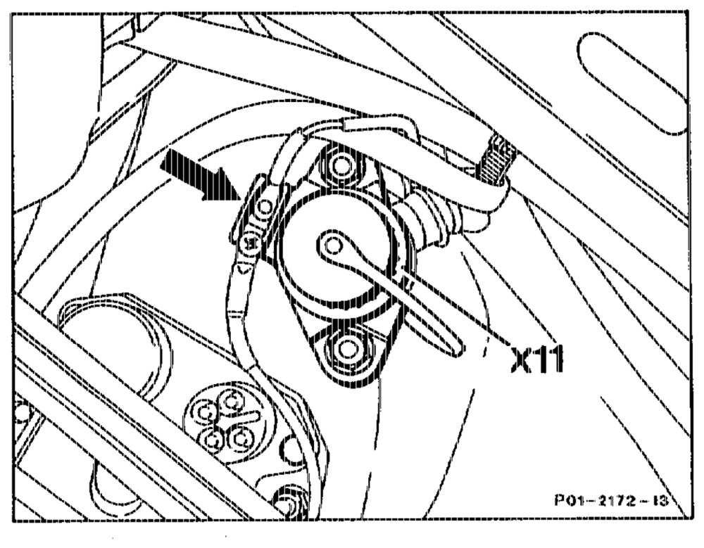
19 Detach cable connector terminal TD (arrow) next to diagnostic socket (X11).
Models 124, 129, 140
20 Unbolt diagnostic socket (11), detach cable from TD sensor on rear of diagnostic socket.
Models 124, 129
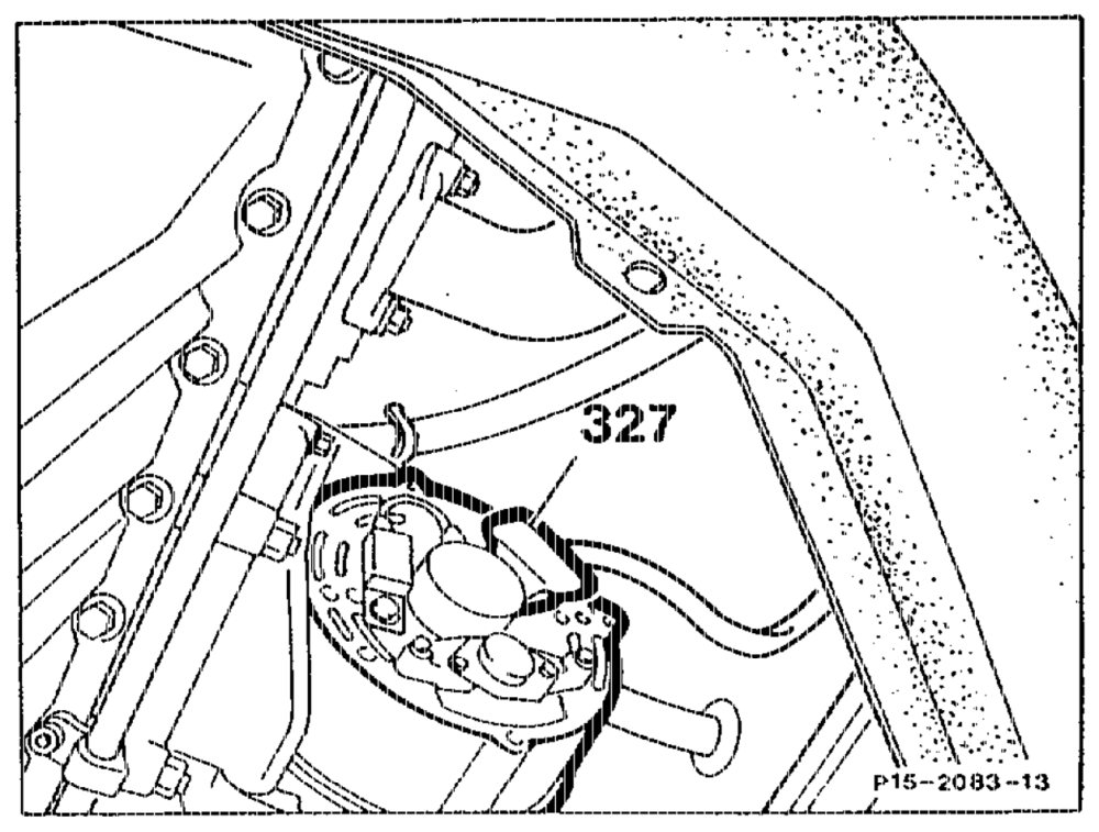
21 Disconnect wiring (327) at the generator.
ahh = RA 01.1215~0300/9
23 Remove heat shields above front and underfloor catalytic converter (rmodel 140 only).
Model 140
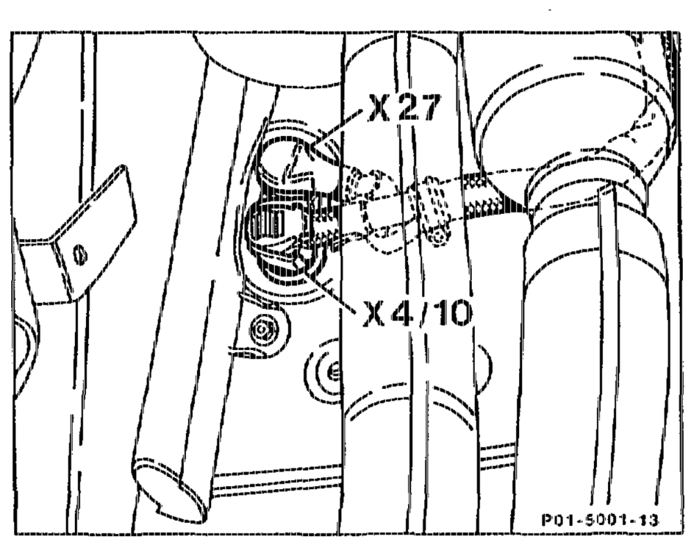
24 Unbolt starter wiring harness X27 and terminal 30 at screw connection X4/10 on front right of firewall from below.
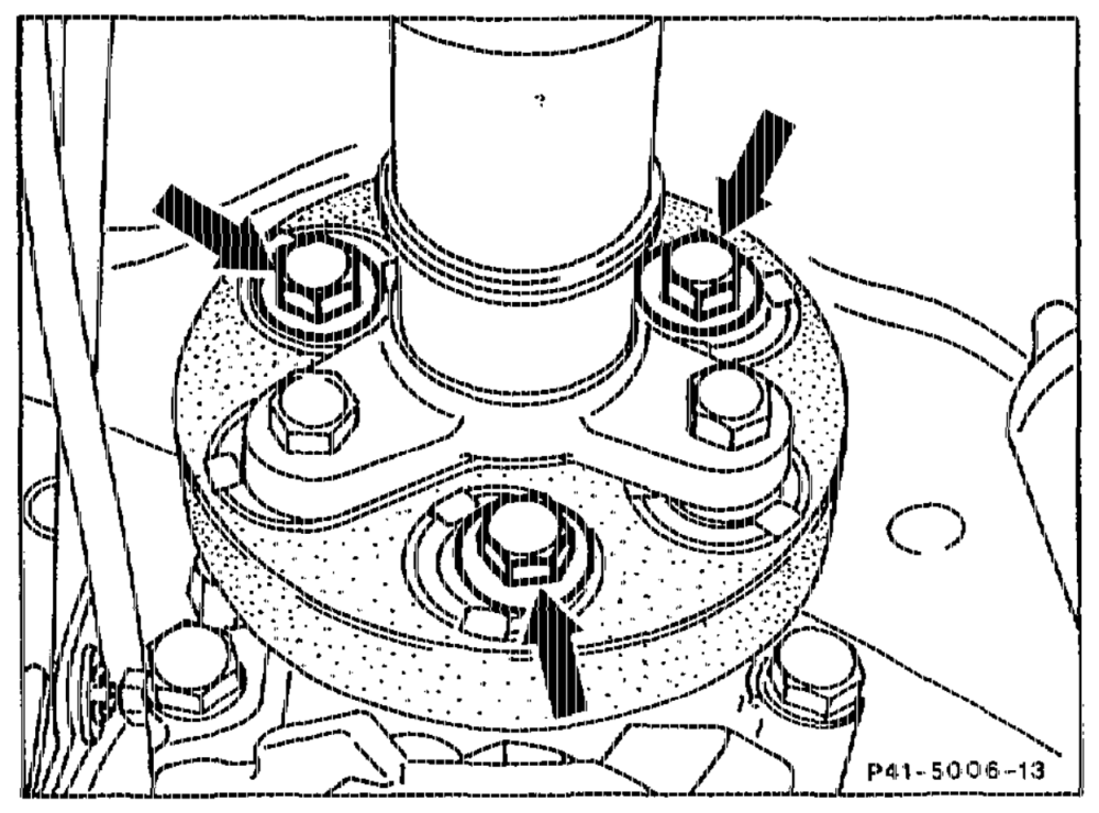
25 Detach propeller shaft by unscrewing bolts (arrows).
Note The propeller shaft is balanced together with the flexible joint.
26 Slacken bolts for propeller shaft interrnediata bearing but do not remove.
adi = RA 01.1215-0300/10
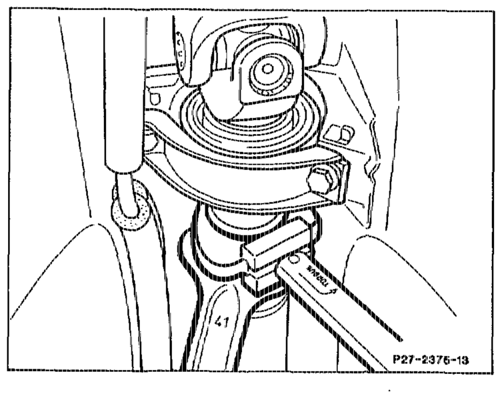
peller shaft. Push back propeller shaft as far as possible. Tightening torque 30–40 Nr.
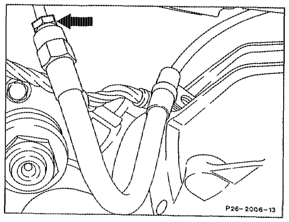
28 If manual transmission fitted: take shift rods off the transmission shift levers after pressing off the clip locks.
29 if manual transmission fitted: separate hydraulic pipe (arrow) to the slave cylinder at the hose connection. Seal pipes with dummy plugs or extract fluid fram the rear chamber of the combined expansion reservoir.
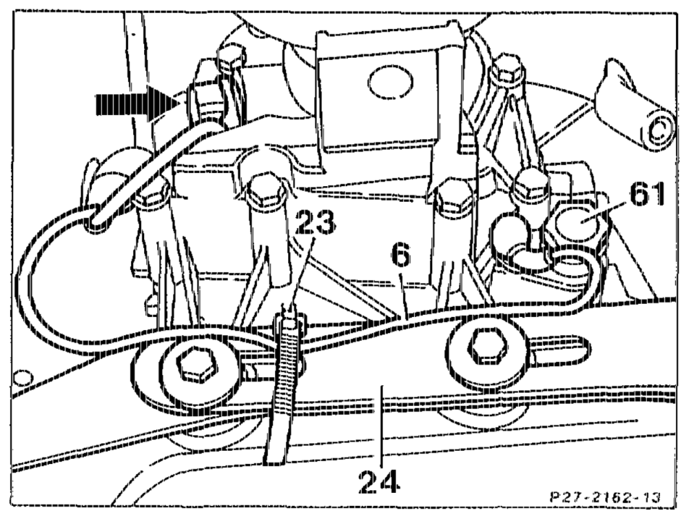
30 If automatic transmission fitted: slacken cable strap (23) and unscrew cable (6) at the kickdown solenoid valve (61) or pull off. Unscrew fastening bolt for the pulse generator (arrow) and pull out the pulse generator.
31 Unbolt ground cable at transmission.
wth = RA O1.1215-0300/11
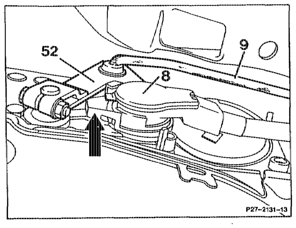
(8).
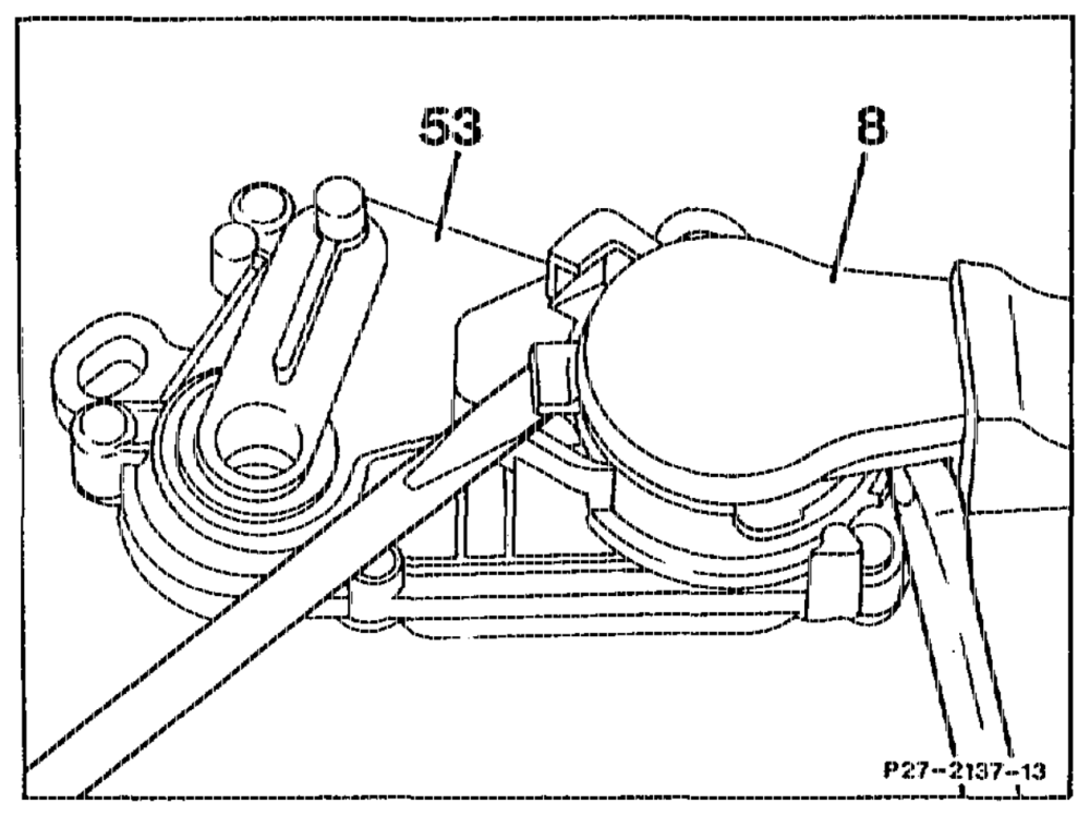
LN The connector for the starter lockout switch is secured by a locking element (white plastic ring, arrow). Before pressing off the connector, the locking element must be turned up (direction of arrow). Detach shift rod (9) in the range selector lever.
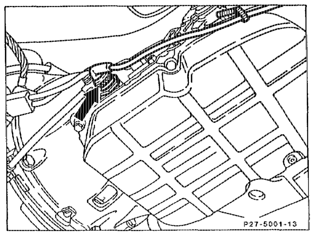
33 Use two screwdrivers to carefully press off the connector (8) at the cable outlet and at the tab.
34 Unscrew connector for transmission overload protection (arrow).
phn = RA 01.1215-0300/12
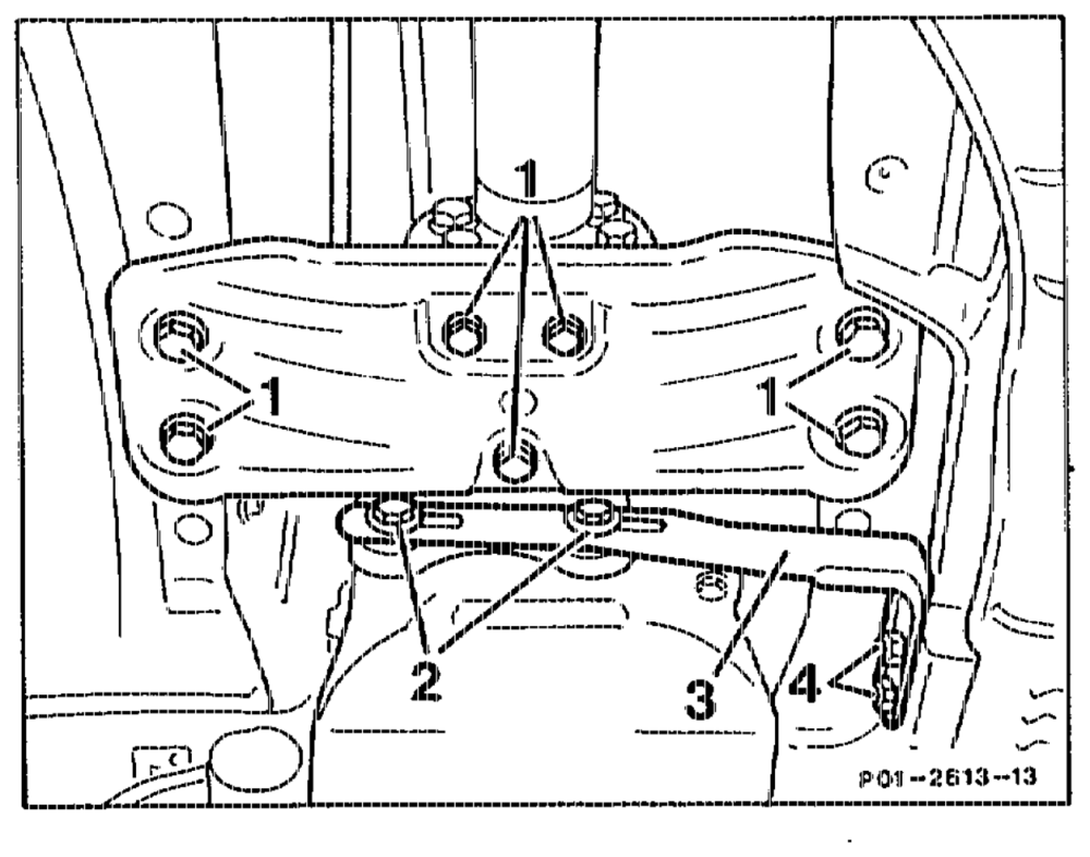
engine. Adjust engine hoist so that the engine can be raised horizontally.
Support transmission in trolley jack or in 36 inspection pit lift.
37 Unbolt rear engine support without engine mounts. Unscrew bolts item 1.
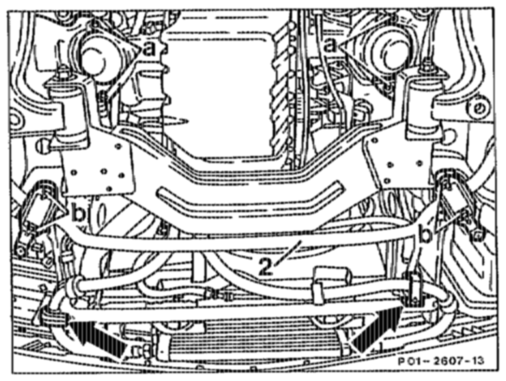
38 Unscrew securing bolts (2) of the exhaust bracket (3) at the transmission.
39 Unscrew bolts (a) at the left and right front engine mounts from below.
Model 14.0
Insert guard plate between component 40 compartment wall and engine.
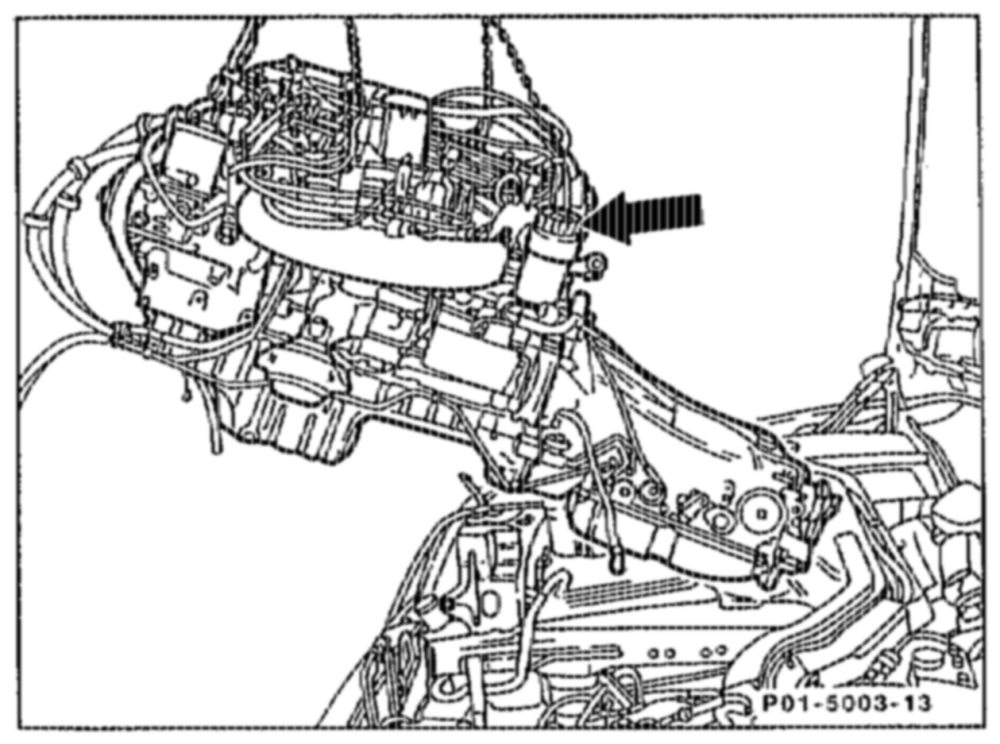
41 Move engine together with transmission into angled position and lift out of engine compartment by repositioning engine hoist several times, and install in the sare way.
Note When tilting engine, pay attention to rear lifting lug and to oil filter (arrow).
oti RA 01.1215-0300/19
Installation note model 140 Before installing the engine, install right engine mount in front suspension, left engine mount can be installed with the engine.
43 Examine front and rear engine mounts.
44 Examine coolant, oil and fuel hoses.
45 If automatic transmission fitted, adjust cable for control pressure (27-100).
46 Check tightening torque of oil drain plugs.
47 Adjust oil level in engine and transmission to correct level.
48 Pour in coolant, check anticorrosion/ antifreeze agent, adjust to correct ratio 20-0100).
49 Check idle speed (07-2056).
Note if engine is replaced, read fault memory of the following control modules and erase any faults which may be stored.
© CFI control module LH-SFI control module ® DIVVKSS ignition control module Electronic accelerator (if fitted) Diagnostic module (California), see Diagnosis Manual Engine Volume 2.
tinge = RA 01.1215–0300/14
B. Model 202
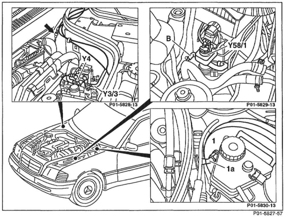
Preceding work: Operation no. of operation texts and work units or standard texts Warning instructions when hood open (01-0085) and flat rates: Bottorn engine compartment panel removed 01-2400 Viscous fan removed (20-3120) Radiator removed (20-4200) Hot film air mass sensor removed (ARO7.5″ 11 14530 ») Air cleaner cross pipe removed (ARO9.10-8031G) Air cleaner removed (AROS. 10-1050D)
HAC fitted: oo. ee ee eee ee attach guard plate to condenser. Engine wiring harnesS 1… 0.0… ee eee eee disconnect, connect (01-0310). Vacuum pipes at switchover valves (3/3) and (Y4) wo. eke eee sete eee wees detach, fit on. Vacuum pipe (arrow) at connection ………. detach, fit on. Line (B) at regeneration switchover valve (Y58/1) oo… eee See eee eee : detach, fit on. facuum line (1a) at brake servo unit (1) ……. unbolt, bolt on.
hie RA 01.1215-0300/15
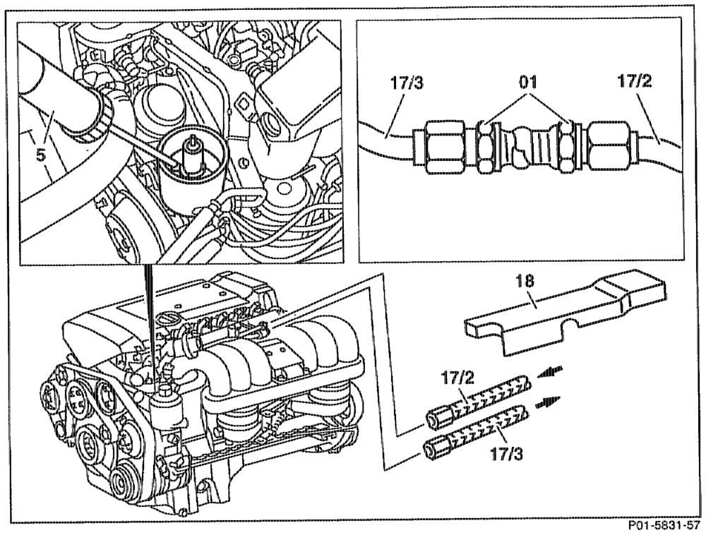
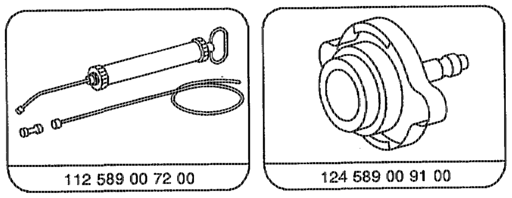
Cable duct cover (18) remove, install. Fuel filler Cap oe ee eee eee open, release pressure in fuel tank. Fuel pipes (17/2) and (17/3) at fuel distributor disconnect, connect (07.5-1451). Fuel pipes (17/2) and (17/3) with union (01) (shop-made) seal. Bowclen cable of accelerator control detach, attach (AR46.30-001 0A). Power steering pump: extract oil from reservoir with handpump (5) 112 589 00 72 00 for extracting oil.
Note Filling, bleeding power steering pump (46-7150).
otiy §=RA 01.1215-0300/16
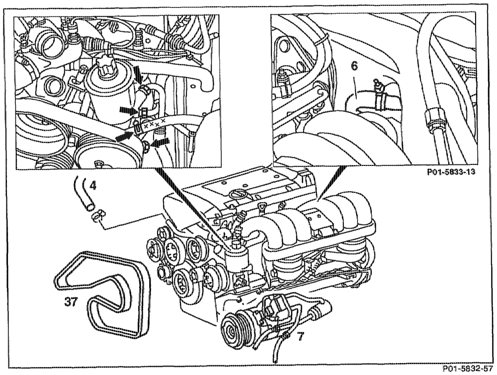
Suction and pressure oil pipes (arrows)… unbolt at power steering pump or at tandem high pressure pump, bolt on.
Note Bleed pressurized oil pump (level part) of tandem pump (AR32.30-0630A). Coolant hoses (4) and (6)… 0 eee eee ee disconnect, connect. IAC fitted: 0… ec ee eee remove poly V-belt (37), install (13-1200). if AC fitted: …….. see eee een eee eee unbolt AC compressor (7) with piping connected, attach to side of engine compartrnent, bolt on.
tig = RA 01.1215-0300/17
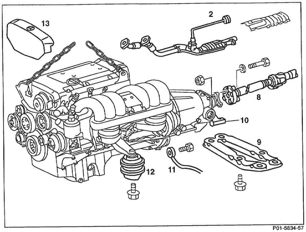
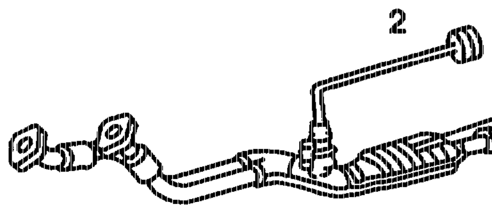
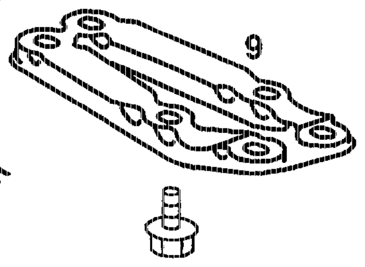
Exhaust systern (2) ….. Leen n ewer eee remove, install. Coolant at crankcase ……. see neee see drain (20-0100). Front propeller shaft (8) at tansmission .» _unbolt, bolt on (AR41.10-0050A). Propeller shaft (8) seen see os push to the rear (AR41.10-0050A). Rear engine carrier (10)… ee ee ee ee remove, install (22-2120). Ground cable (11) at transmission …….. … unNbolt, bolt on. Shift rod if automatic transmission fitted, or shift rods if rnanual transmission fitted detach, attach. Manual transmission: separate hydraulic pipe to slave cylinder at hose connection.
Note Seal pipes with dummy plugs or extract fluid from the rear chamber of combined expansion reservoir. Drag link at relay levers 00… ce eee eee eee detach, attach (AR46.40-0300B). Front engine mounts (12) at body ………… unscrew, screw on (22-2110). Front cover (13) 22… ee eee ee ee eee remove, install. If automatic transmission fitted: …………. remove dipstick, install. Engine hoist ……….. Steen seca attach to both lifting lugs of engine. Engine with transmission wee eee tilt, remove, install. Front engine mounts (12) and rear mounts (10) examine.
ote = RA 01.1215-0300/18
If automatic transmission fitted: ……….0.. adjust Bowden cable for control pressure (27-1000). Oil drain plugS 2… ee ee ee ee eee check tightening torques. Oil level of engine and transmission ………. adjust to correct level. Coolant 2… eee ee eee : pour in, check anticorrosion/antifreeze agent and adjust to correct ratio (20-0100). Leaktightness ….. seen scene eee check. Fault memory ….. Pe ee eee eee ee ewe read, erase; see note.
Special tools
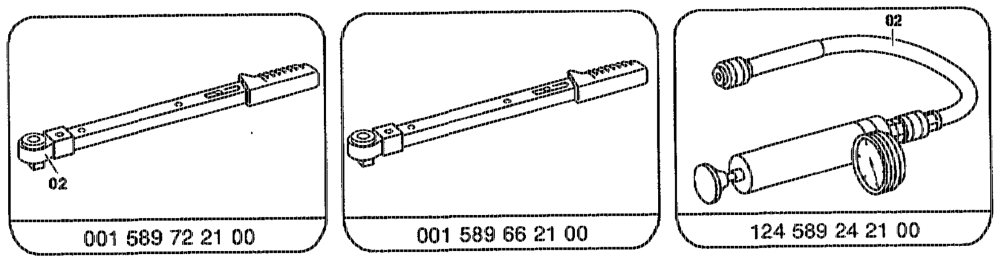
Removal device components model 3188 e.g. Wilbar GmbH (lifting capacity 500 kg) und CO KG 42895 Remscheid
prox. 400 X 680 * trim
ote §=RA 01.1215-0300/19
Note Stored faults which may be caused by disconnecting cables or by simulation during removalinstallation or test work, must be erased in the fault memories after completing operations.
See Diagnosis Manual 2, Index 0: Connecting and using test equipment.
ZN In the case of engine damage involving damage to the pistons, valves etc., parts may have got in as far as the catalytic converter, or pre-catalytic converter. When replacing the engine, it is essential to remove such parts otherwise they will be pulsed back into the cylinders as a result of the gas vibrations in the exhaust system and may once again cause engine darnage. In addition, these parts may cause mechanical damage to the catalytic converter. It is therefore essential to remove any foreign bodies in the exhaust system when dealing with such types of engine damage. Catalytic converters which have been damaged must be replaced.
Model 202 up to August 1994: A gasket 460 251 18 80 is inserted between engine and transmission and a gasket 102 151 00 80 between engine and starter to avoid water which gets in at the separation points corroding the flywheel, clutch etc. These gaskets should be replaced by the sealant 002 989 45 20 when performing repairs. As of August 1994 the water drain at the firewall has been modified.
aie = RA 01.1215-0300/20 ay
Model 210
ial?
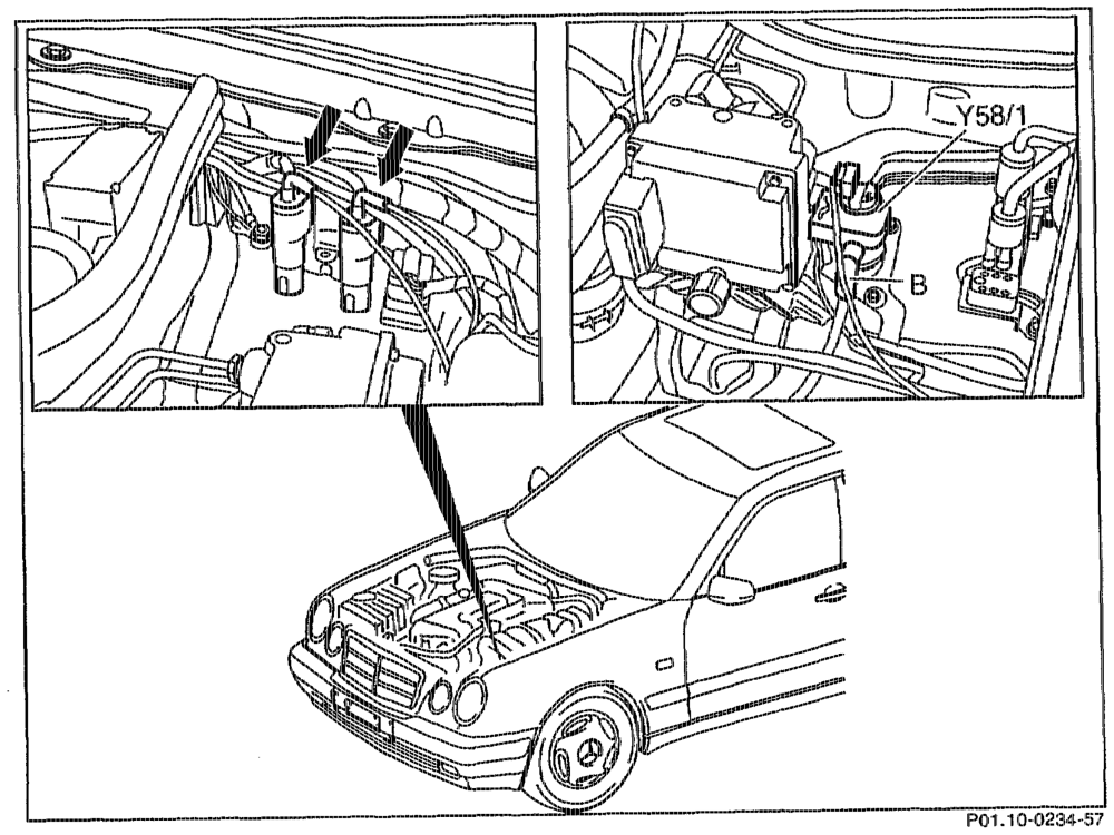
Operation no. of operation texts and work units or standard texts Preceding work: and flat rates: Bottom engine compartment panel removed 01~2400 (Maintenance Manual 6190) Viscous fan removed (20-3120) Radiator removed (20-4200) Hot film air mass filter removed (ARO7.51-1453D) Air cleaner removed
attach quard plate to condenser. If AC fitted: disconnect, connect (01-0310). Engine wiring harness disconnect, fit on. Vacuum pipes (arrows) at switchover valves disconnect, fit on. Pipe (B) at purge control valve (Y58/1) …….. Vacuum pipe to brake servo unit at intake unbolt, bolt on. manifold
whiin = RA 01.1215-0300/21
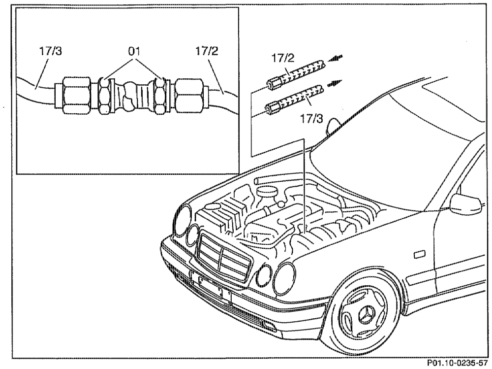
Fuel filler cap open and release pressure in fuel tank. Fuel pipes (17/2) and (17/3) at engine compartment partition disconnect, connect. Fuel pipes (17/2) and (17/3) seal with pipe union (01) (shop-made). Accelerator control Bowden cable detach, attach. Hydraulic fluid of power steering pump oe aa from reservoir with priming pump 2 589 00 72 00 for extracting oil.
Note Filling, bleeding power steering pump (AR46.30-0010A).
tie = RA 01.1215-0300/22
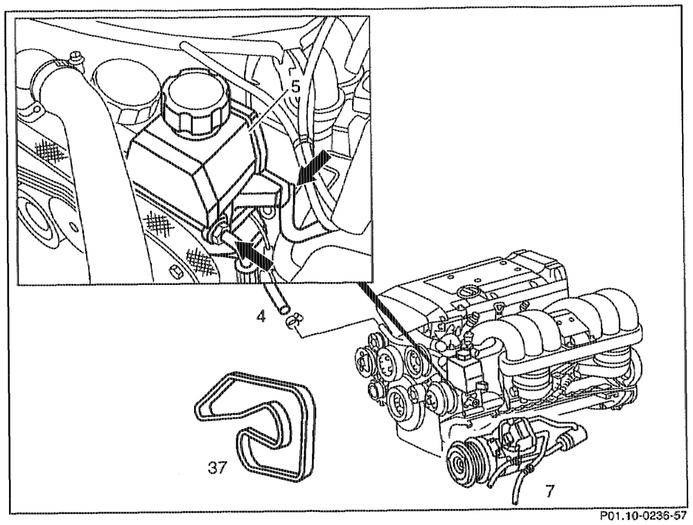
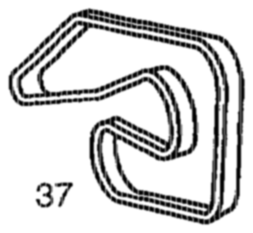
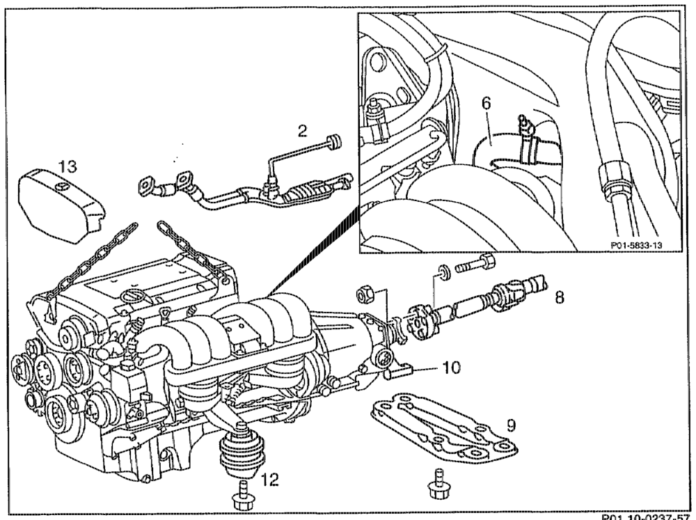
Suction and pressure oil pipes (arrows) at power unbolt, bolt on. steering pump (5) ….. See eee eee tenes Coolant hose (4)… 0. ee ee we ee disconnect, connect. HAC fitted: 2… ee eee see eens remove poly V-belt (37), install (13-1200). HAC fitted: oc. ee eee Leen e nee unbolt AC compressor (7) with pipes connected, attach to side of engine compartment, bolt on.
othe RA 01.1215-0300/23
PO1.10-0237–57
Rear coolant hose (6) 0.00 wees disconnect, connect. Exhaust system (2) …… dene e eee sees remove, install. Coolant at crankcase 6… ee eee drain (20-0100). Front propeller shaft (8) at transmission ……. unbolt, bolt on (AR41.10-00508). Propeller shaft (8) 2… 2… eee ee ee eens push to the rear. Rear engine support (9). eee ee ee remove, install (22-2120). Shift rod of automatic transmission or shift rods of manual transmission ……….0 00066 vee detach, attach. Manual transmission: 2… 2.00. ee ee eee see separate hydraulic pipe to slave cylinder at hose connection.
Note Seal pipes with dummy plugs or extract fluid from the rear chamber of combined expansion reservoir. Engine mount (12) at front suspension support .. —unbolt, bolt on (22-2110). Front cover (13) ……. beeen eee see os remove, install. Engine hoist ……….. see eee eee attach to both lifting lugs of engine; use engine supporting bar if necessary. Engine together with transmission ……. eee Tilt
othe §=RA01.1215-0300/24
Engine 2.0… ce eee eee ee eee remove, install. Front engine mounts (12) and rear engine mounts (10) …….. sce ee eee eee eee examine. if autornatic transmission fitted: ………..0. adjust Bowden cable for control pressure (27-1000). Qil drain plugs ….. see eee eee eee ene check tightening torques. Oil level of engine and transmission ………. adjust to correct level. Coolant ……. vtec wesw eee see sete pour in, check anticorrosion/antifreeze agent and adjust to correct ratio (20-0100). Leaktighiness ……. vee ee eee eee ees examine. Fault memory… ee ee read, erase.
Special tools
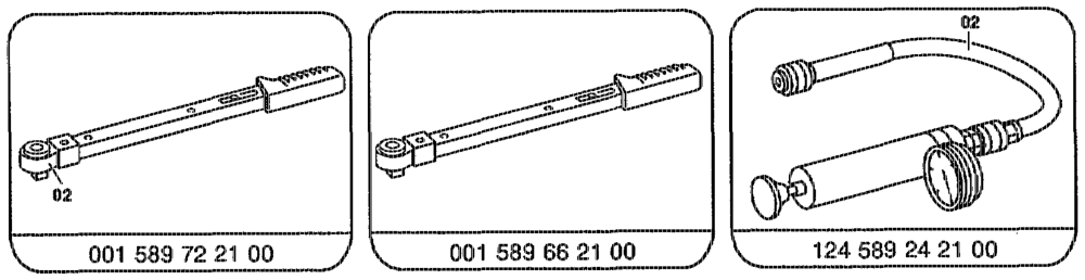
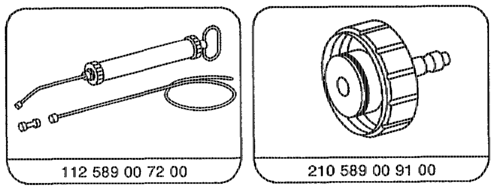
Removal device components model 3188 e.g. Wilbar GmbH (lifting capacity 500 kg) und CO KG ot 42895 Rems
Engine supporting bar e.g. Schairer WeidenstraBe 5 72459 Albstadt Order no. 0304.01.00
niin = RA 01.1215-0300/25
Shop-made tool Guard plate for radiator/condenser sizes approx. 400 x 680 * 1 mm
Note Stored faults which may be caused by disconnecting cables or by simulation during rernoval/ installation or test work, must be erased in the fault memories after cornpleting operations.
See Diagnosis Manual 2, Index 0: Connecting and using test equipment.
AN In the case of engine darnage involving damage to the pistons, valves etc., parts may have got in as far as the catalytic converter, or pre-catalytic converter. When replacing the engine, it is essential to remove such parts otherwise they will be pulsed back into the cylinders as a result of the gas vibrations in the exhaust system and may once again cause engine darnage. In addition, these parts may cause mechanical damage to the catalytic converter. It is therefore essential to remove any foreign bodies in the exhaust system when dealing with such types of engine damage. Catalytic converters which have been damaged must be replaced.
aottie = RA 01.1215-0300/26