Testing fuel pump
WIS 07.3-5701
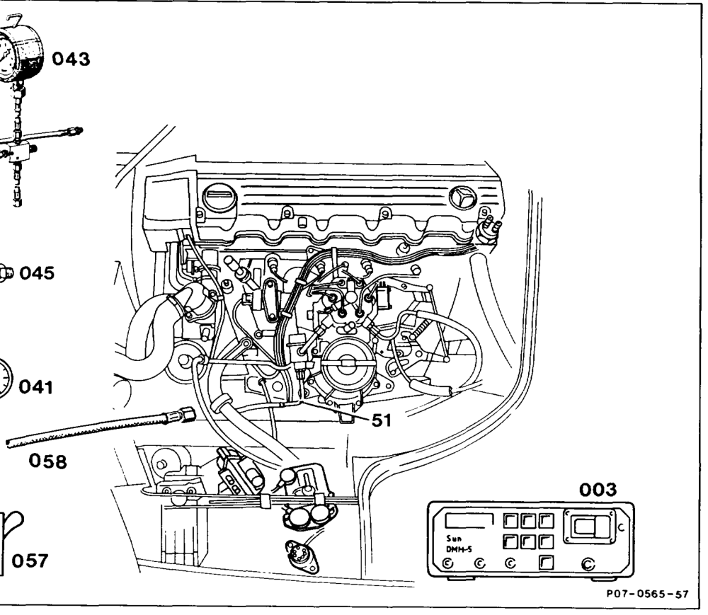
Operation no. of operation texts and work units or standard texts and flat rates: 07-5701 Delivery, 07-5702 Fuel pressure.
____
Current consumption ………..-…20000% test. Specification 6–10 amperes (step 1). Use multimeter tester (003) for this step. Fuel pressure in fuel tank ………….000. release by opening cap. Fuel return line (51)… ee ee eee unscrew. Fuel hose (058) ……………22-.00000shop-made; connect to diaphragm pressure regulator. Delivery 2.2… 00. cece eee eee eee test. Specification 1 liter in not more than 40 seconds. Use measuring beaker (057), stop watch (041) for this step.
ii §=RA 07.3.1112-5701/1
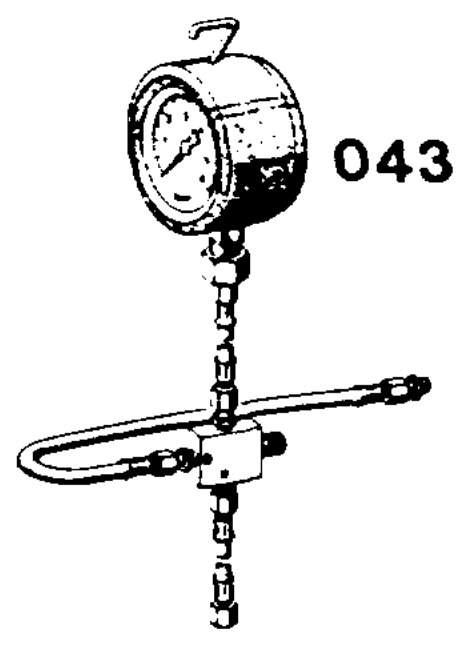
Fuel pressure 2.2.2.0… 0.0.0 eee eee eee test. Specification 2–4 bar gauge. Use testers, pressure measuring device (043) 103 589 00 21 00, connection fitting (045) 103 589 02 63 00, for this step.
Test data
Version 1 fuel pump 2 tuel pumps Designation EKP4 EKP6 MB 002 091 97 01 002 091 59 01 ’) part no.
Bosch no. 0 580 254 943 0 580 254 951
Pierburg, – E2T
two-stage Current 6–10 A *) 4–8 A’) consumption
Test specification Engine not running and voltage at delivery pump at least 11.5 volts.
Delivery ?) Measuring point Fuel return line downstream of diaphragm pressure regulator.
at least 1 liter in 40 seconds
1) Part no. 002 091 88 01. 2) Fuel tank must be at least half full for measuring delivery. 3) For vehicles in KAT version, detach plug connection (G3/2 x 1) of oxygen sensor heating coil.
Special tools
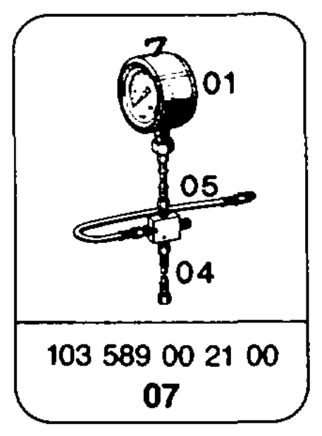
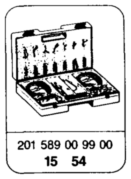
r \ – 103 589 02 63 00
07 Y
Commercially available tools and testers (see Workshop Equipment Manual) Designation e.g. Make, order no. Multimeter Sun, DMM-5 Measuring glass or beaker (at least 1 liter)
Stop watch
iim RA 07.3.1112-5701/2
Shop-made tools Fuel hose approx. 500 mm long
Pipe with sealing cone
Union nut M14x1.5
Note See appropriate wiring diagram volume for wiring diagrams. When the ignition is switched on, the fuel pumps must briefly run (approx. 1 second) (audible).
A. Delivery
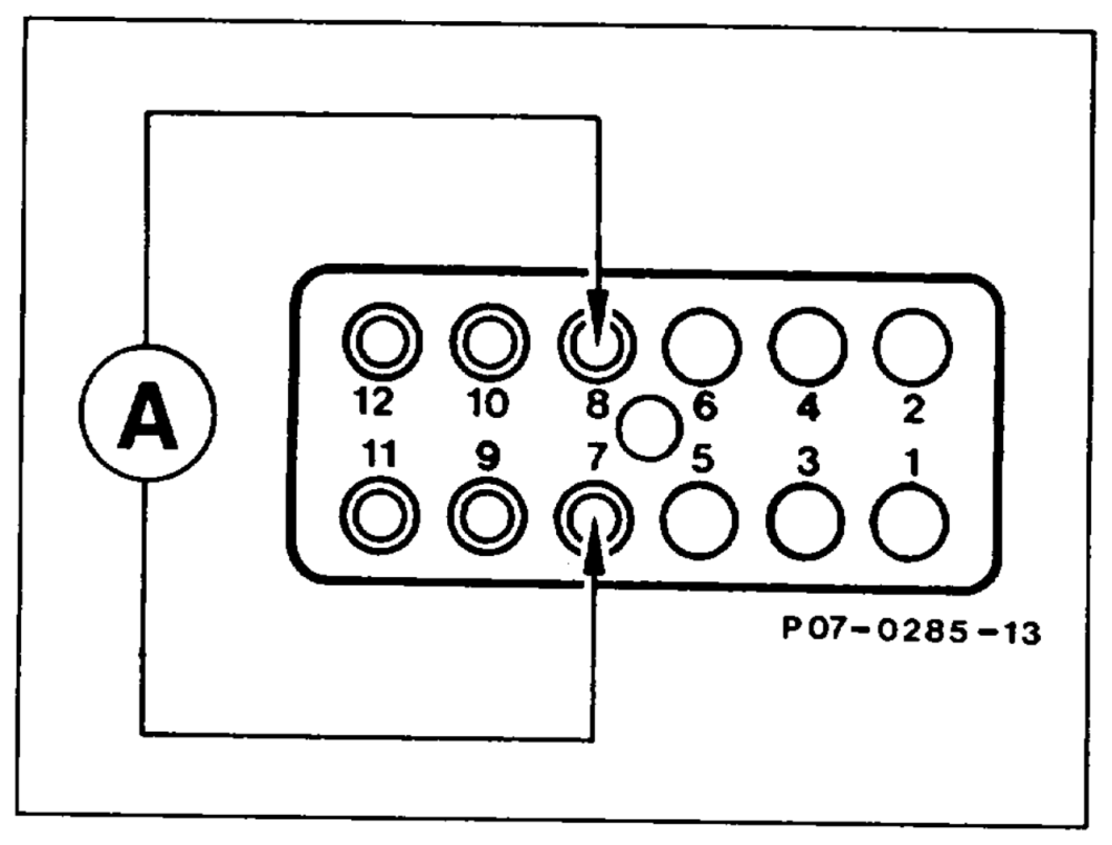
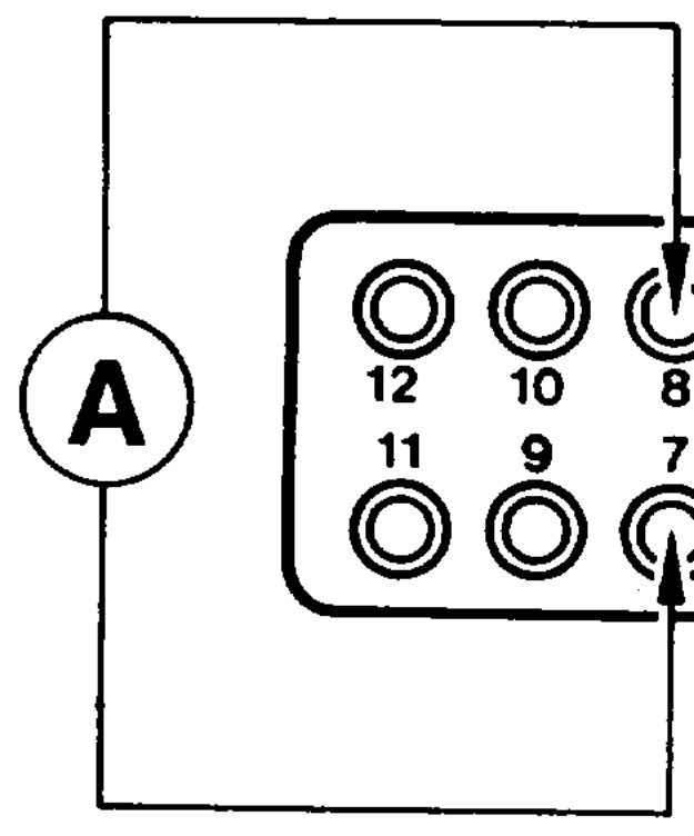
1 Remove fuel pump relays (N16/1 to N16/4). Multimeter set to amperes. Test current consumption at contact 7 (terminal 87) and contact 8 (terminal 30), on mode! 129 engine systems control unit MAS between contacts 1 and 2, for G) @sa) as of model year 1990 on KE control unit (N3) between contacts 11 and 20.
Current consumption 6–10 amperes.
If more than 10 amperes are measured, test as follows:
wim §=RA 07.3.1112-5701/43
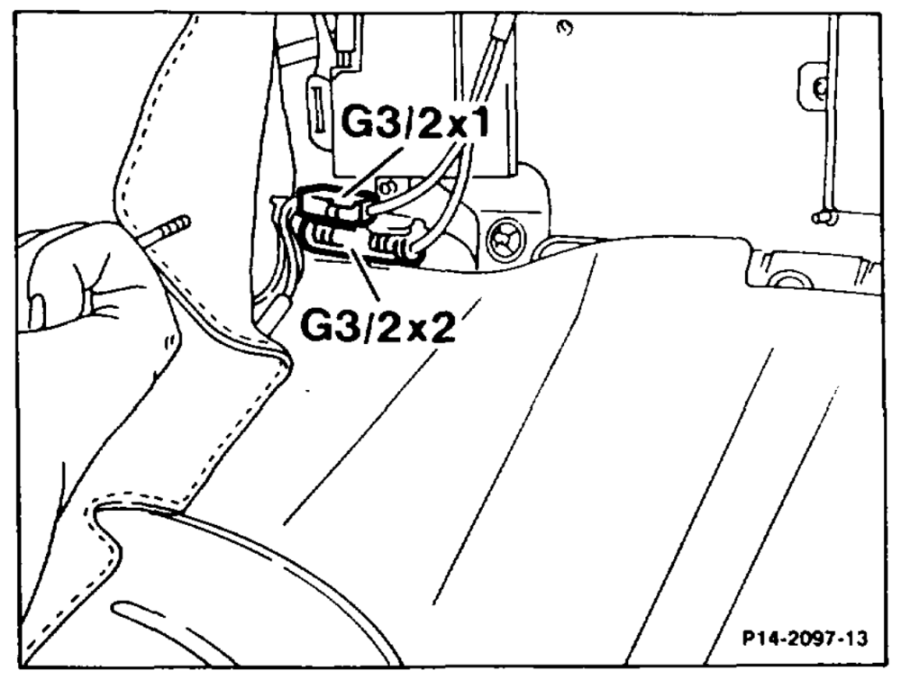
a) Vehicles with KAT Detach plug connection (G3/2×1) of oxygen sensor heating coil and repeat measurement. Located on models 107 and 126 in right footwell below floor panel. Test current consumption of oxygen sensor 0.5–1.7 A, if necessary oxygen sensor (see 07.3-0121, test program with contact box, on/off ratio readout 50%).
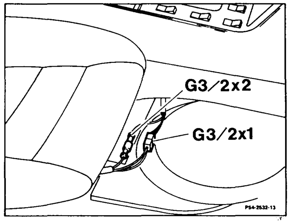
b) Test fuel pressure (see section „B”).
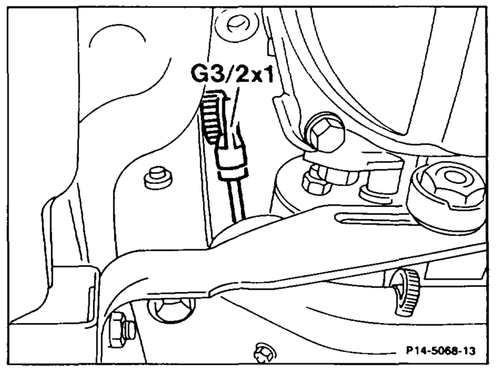
Located on models 124, 201 on right at front seat. G3/2×1 Plug connection, oxygen sensor heating coil G3/2x2_ Plug connection, oxygen sensor signal
Model 129 G3/2x1_ Plug connection, oxygen sensor
iim §=RA 07.3.1112-5701/4
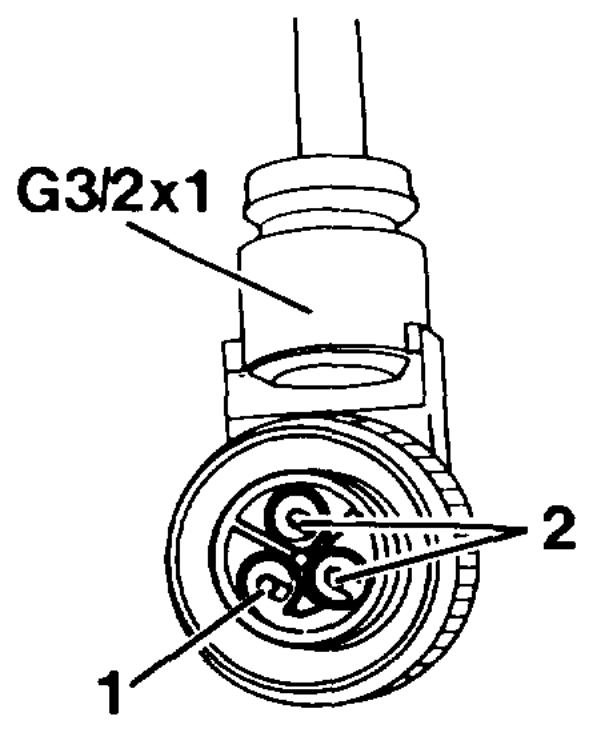
Model 129 G3/2x1_ Plug connection, oxygen sensor
1 Oxygen sensor signal
2 Oxygen sensor heater PO?-2029-134
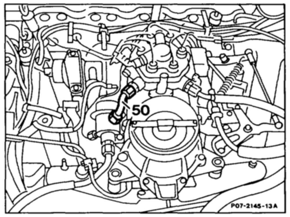
2 Unplug wiring from multimeter. The delivery of the fue! pump should be tested in the fuel return. Reduce fuel pressure in fuel tank by opening cap. Unscrew fuel return line (50) at the diaphragm pressure regulator and seal.
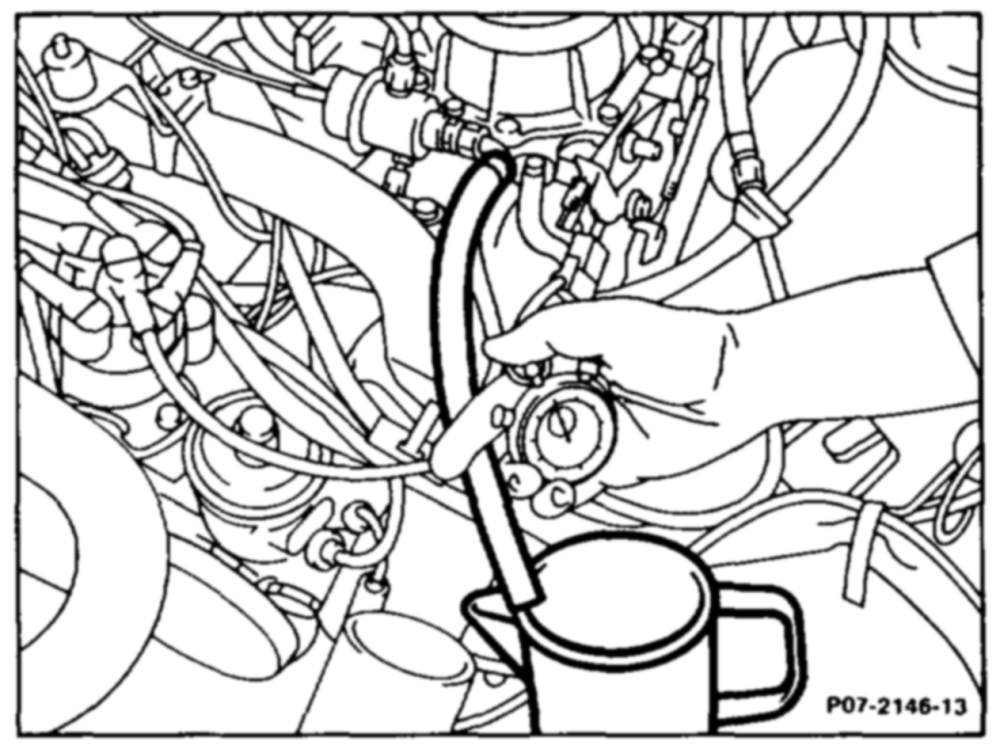
3 Screw shop-made fuel hose onto diaphragm pressure regulator and hold in measuring glass or beaker.
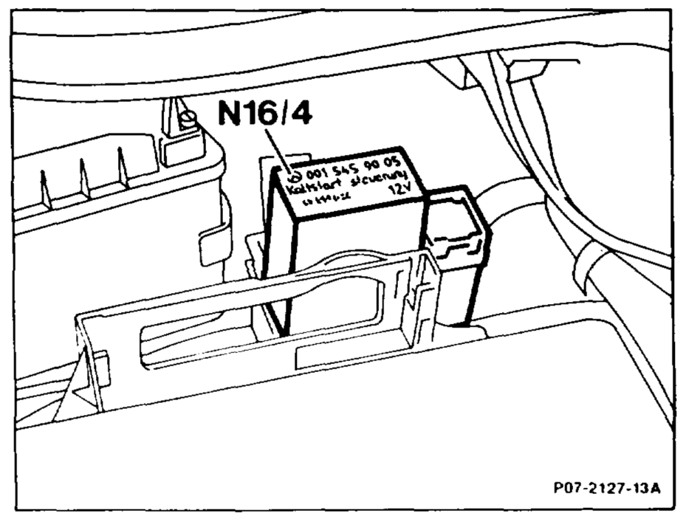
4 Bridge contacts 7 and 8 at fuel pump relays (N16/1 to N16/4), on model 129 engine systems control unit MAS between contacts 1 and 2, for @9 as of model year 1990 on KE control unit (N3) between contacts 11 and 20. This energizes the fuel pump.
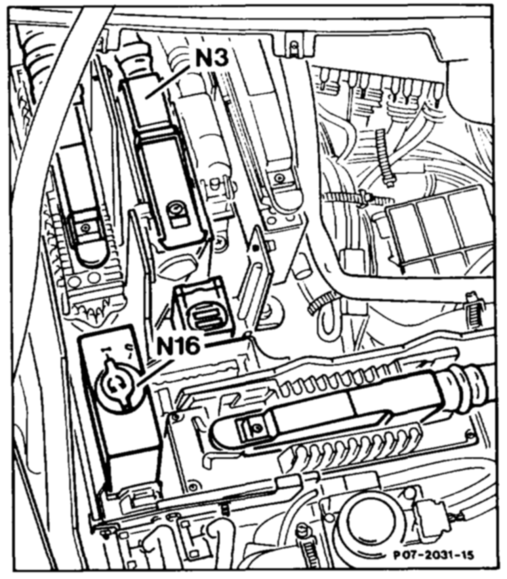
N3 KE control unit N16 Engine systems control unit
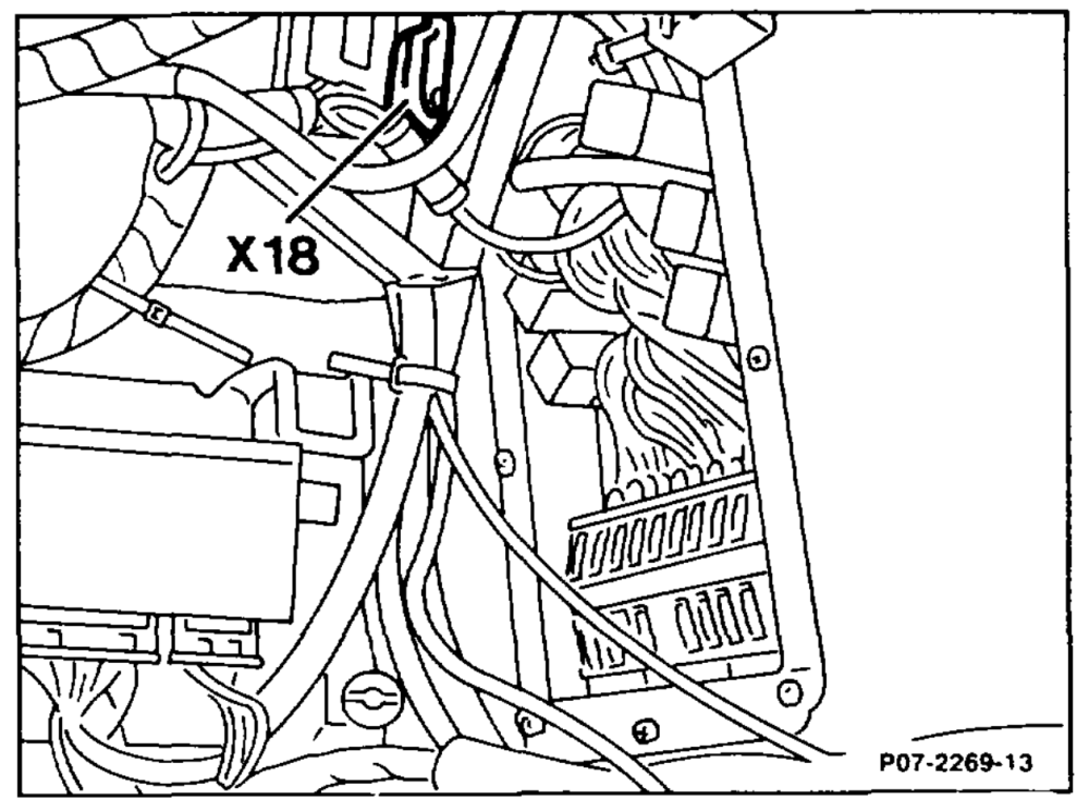
On model 107 detach 8-pin coupling of taillamp harness (X18) in left footwell below floor panel. Connect terminal 2 to terminal 30 (terminal junction next to overvoltage protection).
Model 107
After 40 seconds or before measuring glass/beaker overflows, remove bridge.
Specification: 1 liter in not more than 40 seconds with a minimum voltage of 11.5 volts at fuel pump.
5 If delivery is less than 1 liter in 40 seconds, test the following points:
wie §=RA 07.3.1112~-5701/6
a) Test voltage at fuel pump. Specification at least 11.5 volts. b) Check whether strainer in feed connection of fuel distributor is blocked. c) Check fuel lines for restrictions (pinched lines). d) Pinch off leak line between fuel accumulator and intake damper. Once again check delivery. If the specified delivery is achieved, replace fuel accumulator. e) Replace fuel filter.
6 If the delivery remains too low, determine the faulty fuel pump by measuring pressure (section ””B”).
7 Connect fuel return hose, install relays.
B. Fuel pressure
Note
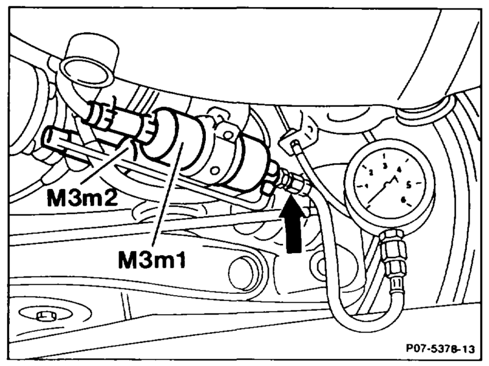
Measurement only with double pump. Arrangement of protective box and fuel pump, see removing and installing fuel pump (07.3-5710).
1 Unscrew cap nut at fuel pump (M3m1); fit on threaded connector, part no.103 589 02 63 00, and pressure measuring device, part no. 103 589 00 21 00 (arrow).
Models 124, 201 with 2 fuel pumps
wiime =RA 07.3.1112-5701/7
2 Remove fuel pump relays (N16/1 to N16/4) and bridge the two contacts 7 and 8 (terminals 30 and 87), on model 129 engine systems control unit MAS between contacts 1 and 2, for Ce as of model year 1990 on KE control unit (N3) between contacts 11 and 20.
4 Read off pressure on gauge. The reading must be between 2-4 bar. If it is below 2 bar, fuel pump 1 (M3m1) is faulty. If it is more than 4 bar, fuel pump 2 (M3m2) is faulty.
5 Detach pressure measuring device. Fit on Cap nut, install fuel pump relays and check for leaks.
6 Install protective box.