Testing electronic idle speed control
WIS 07.3-2006

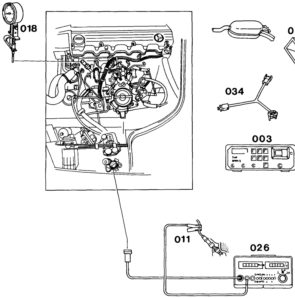
Preceding work: Operation no. of operation texts and work units or standard texts Testing, adjusting engine (07.3-1100). and flat rates: 07-2006.
Testers 2… eee eens connect: oil remote thermometer (018) 124 589 07 21 00, trigger clamp (011), engine tester (026), multimeter (003), test cable (034) 102 589 04 63 00. Extraction device (014) ………..-..0–5– position at exhaust tailpipe.
wae AA 07.3.1112-2006/1
Engine oil temperature …………..20065 approx. 80 °C. Electronic idle speed control …………-… test (see table). Control range 1.2.2… eee eee test (see table). Function of idle speed air valve …………. test. Briefly apply battery voltage for this step; valve must be heard to operate. Voltage supply …………..2 020002 eee test according to wiring diagram. Smooth engine running …………….085 check. Switch on all anciilaries for this step.
Test and adjustment data
Basic version
| Engine | Version | Idle speed 1/min | Control range |
| 103.940/941/942/943 | RUF _ NV (RUF) KAT | 650-750 | 35–45% 21–27° A |
| 103.980 | Std. Std. KAT | 600-700 | |
| 103.981 | RUF NV (RUF) KAT | Bn | |
| 103.982/983/985 | RUF NV (RUF) KAT | up to 5/90: 600-700 as of 6/90: 650-750 | |
| 103.984 | RUF KAT | 650-750 | |
wie §=RA 07.3.1112-2006/2
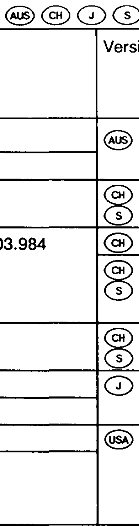
National version Gs) Engine Idle speed
1/min Control range 35–45% 103.94 700 + 50 21–27° & 103.98 650 + 50 103.94 KAT 700 +50 KAT 103.98 except CG) 780 +50 KAT 650 + 50; KAT as of 06/90 750 +50 103.984 KAT 700 +50 KAT 103.94 700 +50 35–45% 103.98 650 +50 103.94 700 +50 103.98 650 + 50; as of model year 1990 700 +50
Special tools
Commercially available testers (see Workshop Equipment Manual)
| Designation | e.g. Make, order no. |
| Multimeter | Sun, DMM-5 |
| Engine tester | Bosch, MOT 002.02 |
etme RA 07.3.1112-2006/3
Symbols for test mode with multimeter
Symbols for testers
+@*+ Voltage measurement (volts, DC akg Multimeter Contact voltage) Connector Current measurement (amperes, Ground DC) Resistance measurement (ohms)
Test conditions
Note e@ Engine oil temperature approx. 80°C See appropriate wiring diagram volume for
© Battery voltage 11-14 V
wiring diagrams. The voltage on analog instruments may drop to 0 volts. Engine speed increases when the coupling is unplugged from the microswitch.
| Test step | Test scope | Operation/ Requirement | Possible cause/Remedy |
| 1.0′) | Test idle speed air valve (Y6) | Engine: idling | Open circuit in wiring KE control unit (N3) |
| 2.0′) | Test idle speed air valve (Y6) | Engine: idling | Idle speed air valve faulty, Open circuit in wiring |
| 3.0 | Engine: idling Coupling at idle speed air valve (Y6) unplugged | Replace idle speed air valve | |
| 4.0 | Ignition: ON | Open circuit in wiring | |
| 5.0 | Resistance at idle speed air valve | Ignition: OFF Coupling at idle speed air valve (Y6) unplugged | Idle speed air valve (Y6) |

1) Test step 1.0 for all models as of model year 1990, test step 2.0 for all models up to model year 1989.