Replacing, centering air flow sensor plate and checking, adjusting
WIS 07.3-1665
Operation no. of operation texts and work units or standard texts and flat rates: 07-1665, 07-1612.
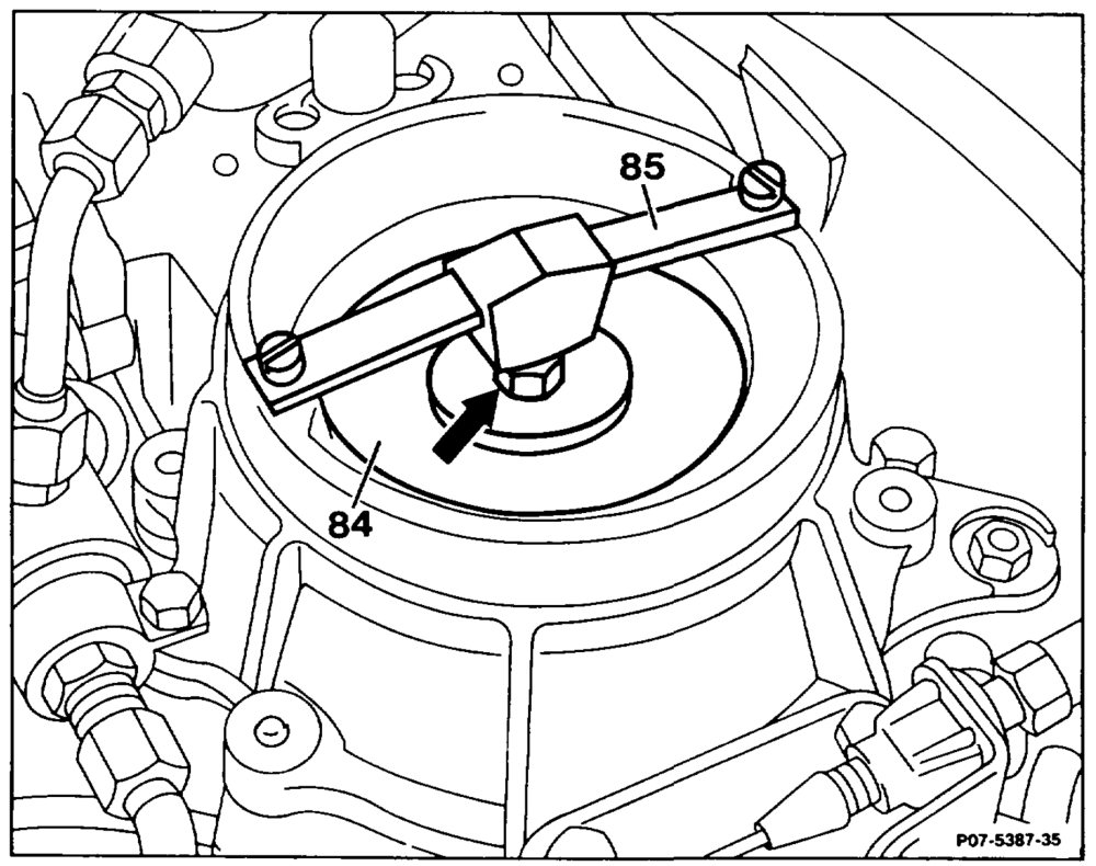
Stop bar (85) 2… eee unscrew, screw on. Micro-encapsulated securing bolt (arrow) …… heat with hot air fan.
Unscrew carefully (risk of shearing off). Hole 2… ee ce ee tee clean with M6 tap. Air flow sensor plate (84) and packing washer ..__ insert. Lightly screw on micro-encapsulated securing bolt. Air flow sensor plate 2… 2.2… 02.22.0005 center (pay attention to installation notes). Securing bolt 0.0.0… cee eee eee tighten to 5–5.5 Nm. Air flow sensor plate 2.2.2… eee ee eee check that it operates freely and without sticking. Re-center if necessary. Idle speed 26… ee eee adjust (07.3-2053).
wim = RA 07.3.1132-1665/1
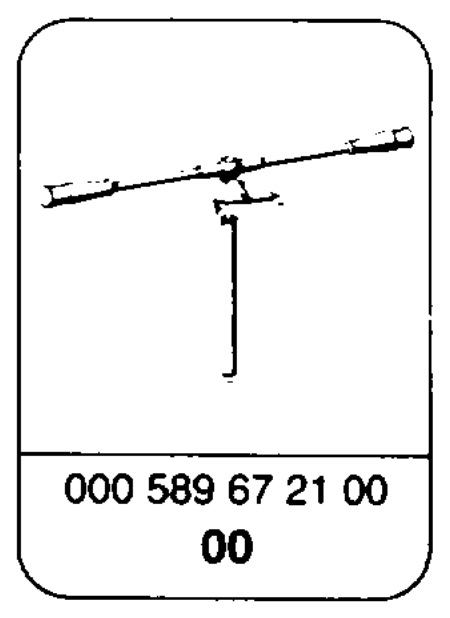
Special tool
Commercially available tools and testers (see Workshop Equipment Manual) Designation e.g. Make, order no.
Hot air fan
M6 tap
Installation notes
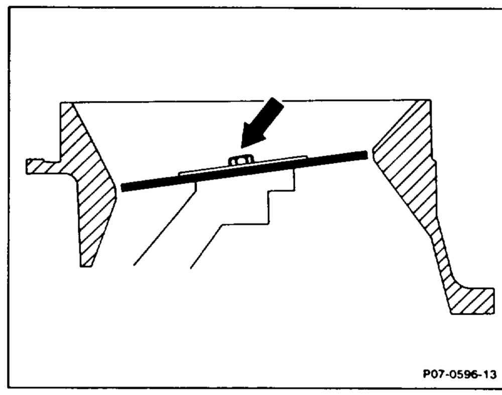
1 Install parts of repair kit. Insert air flow sensor plate and packing washer. Slightly screw on micro-encapsulated securing bolt (arrow, selflocking).
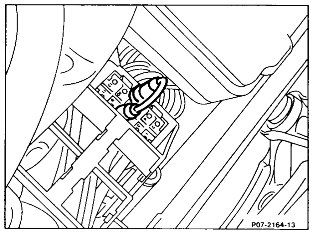
2 Center air flow sensor plate. To do this, remove fuel pump relay and briefly bridge the two contacts 7 and 8, on model 129 engine systems control unit MAS between contacts 1 and 2, for Gs CG as of model year 1990 at KE control unit (N3) between sockets 11 and 20 to build up pressure.
lime =RA 07.3.1132-1665/2
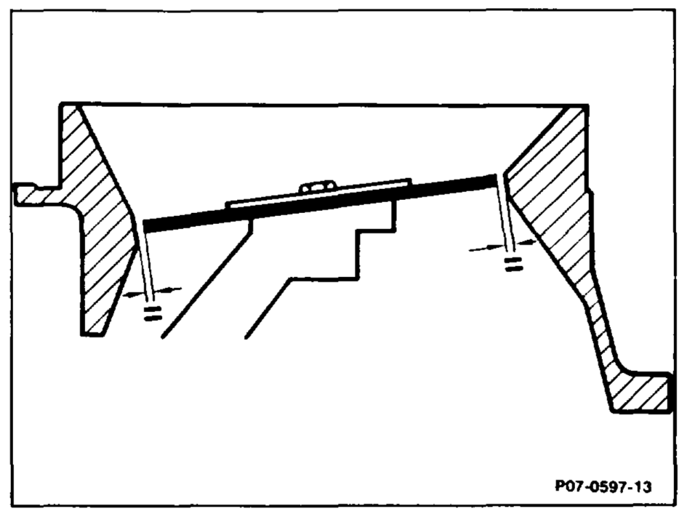
3 Check with a feeler gauge (approx 0.5 mm) that the air flow sensor plate is accurately centered. The air flow sensor plate must also not stick even if slight pressure is applied to the side (bearing play eliminated). Tighten securing bolt to 5-5.5 Nm and install stop bar.
4 Check that air flow sensor plate operates freely. To do this, press sensor plate down by hand. The sensor plate must not jam when this is done. Release sensor plate; as it moves back, the sensor plate must also not jam. It must audibly strike against the resilient stop. Recenter air flow sensor plate if necessary.
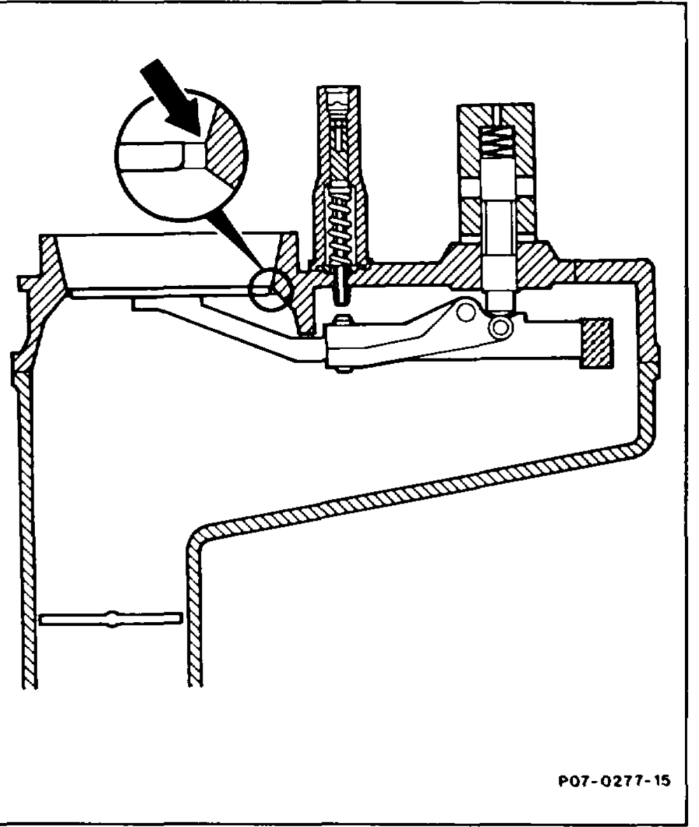
5 Check zero position (rest position) of sensor plate. The top edge of the sensor plate must be flush with the top edge of the cylindrical part (arrow) on the air funnel. It is permissible for the plate to be higher by not more than 0.2 mm.
In this position, a play of 1–2 mm must exist when the air flow sensor plate is pressed as far as the control plunger.
wim RA 07.3.1132-1665/3
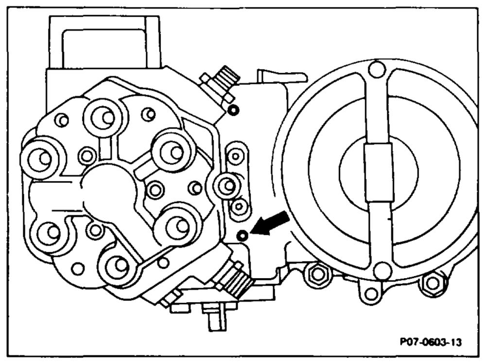
6 Adjust zero position of air flow sensor plate. a) If the position is too high, knock guide pin (arrow) in appropriately with a drift. b) If the position is too low, remove mixture control unit and knock guide pin out from below (07.3-1668).
AN Do not knock guide pin in too deep. It is essential to avoid moving the guide pin several times in both directions as the interference fit seat of the pin will be insufficient.
7 Install stop bar and fuel pump relay.
8 Adjust idle speed (07.3-2053).