Removing and installing throttle valve body
WIS 07.3-6210
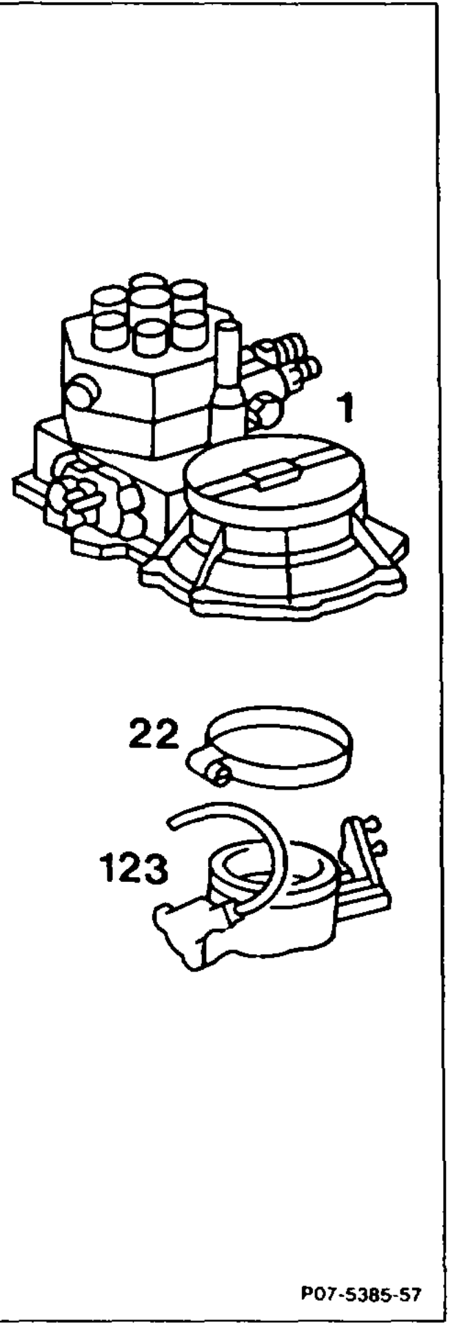
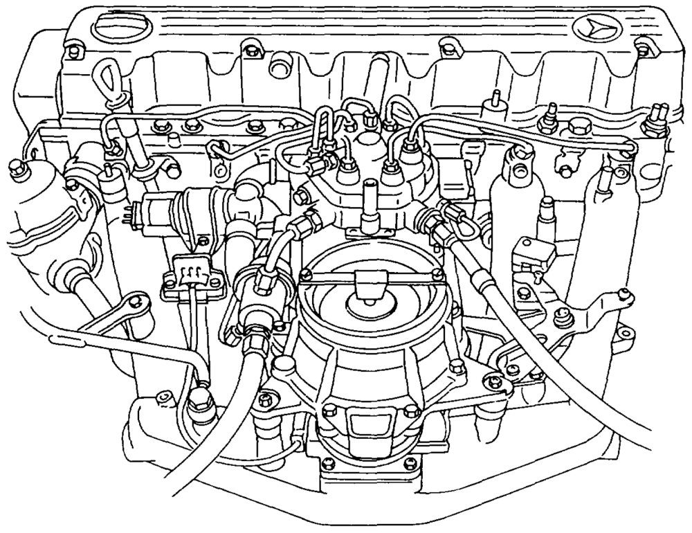
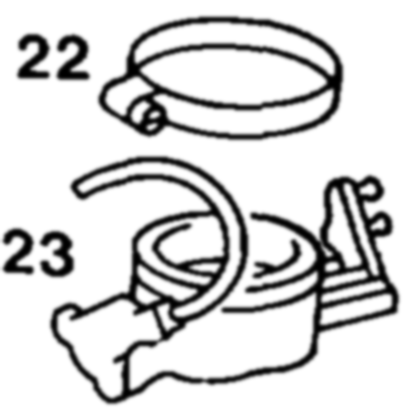
Operation no. of operation texts and work units or standard texts and flat rates: 07-6210.
Hose clip (22) 2… 0.2… ee eee eee ee slacken, tighten. Mixture control unit (1)… 2–2 eee eee remove, install (07.3-1668). Return spring and accelerator control rod at throttle valve body …………0.—0000detach, attach. Throttle valve body (123) ……….-….05– unscrew and take out. When installing, use new seal. Tightening torque 25–30 Nm as reference value.
wim RA 07.3.1132-6210/1
Vacuum lines and electrical connection for throttle valve switch disconnect, connect. Fulcrum lever adjust (30-1010). Idle speed adjust (07.3-2053).
Throttle valve body
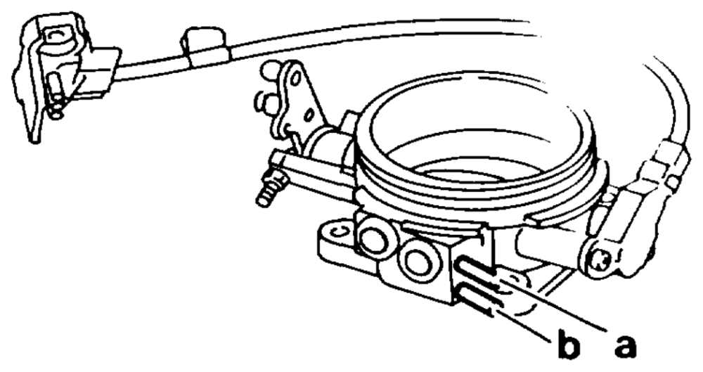
a To thermovalve b Extraction line connection to regeneration valve for fuel evaporation contro! system
Throttle valve body, model 129
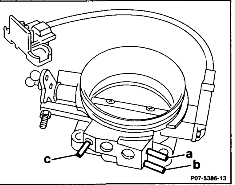
With 3 vacuum connections
a_ Regeneration valve contro! line b Regeneration line c Exhaust gas recirculation control line
Notes
Model 129
Throttle valve body with manual and automatic transmission with improved throttle valve switch.
Production breakpoint: March 1990
Model Engine Engine end no. Engine end no. automatic transmission manual transmission
129.060 103.984 000259 000966
wie = RA 07.3.1132-6210/2
Models 124, 126, 129, 201
Throttle valve body with automatic transmission and ASR with modified opening angle and improved throttle valve switch.
Production breakpoint: April 1990
Mode! Engine Engine end no. automatic transmission
124.026 103.940 082979
124.030/050/090 103.983 209949
126.020 103.941 015255
126.024/025 103.981 115904
129.060 103.984 001049
201.029 103.942 046790
Note Throttle valve bodies which have to be replaced after a clear diagnosis, should be replaced in future only in combination with the throttle valve switch.